EP0957767B1 - Ergonometrischer stethoskopkopf - Google Patents
Ergonometrischer stethoskopkopf Download PDFInfo
- Publication number
- EP0957767B1 EP0957767B1 EP96938634A EP96938634A EP0957767B1 EP 0957767 B1 EP0957767 B1 EP 0957767B1 EP 96938634 A EP96938634 A EP 96938634A EP 96938634 A EP96938634 A EP 96938634A EP 0957767 B1 EP0957767 B1 EP 0957767B1
- Authority
- EP
- European Patent Office
- Prior art keywords
- chestpiece
- ergonometric
- gripping surfaces
- user
- center portion
- Prior art date
- Legal status (The legal status is an assumption and is not a legal conclusion. Google has not performed a legal analysis and makes no representation as to the accuracy of the status listed.)
- Expired - Lifetime
Links
- 210000003811 finger Anatomy 0.000 claims description 32
- 210000003813 thumb Anatomy 0.000 claims description 15
- 230000004044 response Effects 0.000 claims description 2
- 230000005540 biological transmission Effects 0.000 description 7
- 230000009471 action Effects 0.000 description 2
- 230000009977 dual effect Effects 0.000 description 2
- 230000007246 mechanism Effects 0.000 description 2
- 241000251468 Actinopterygii Species 0.000 description 1
- 238000010276 construction Methods 0.000 description 1
- 210000005069 ears Anatomy 0.000 description 1
- 230000036541 health Effects 0.000 description 1
- 238000010348 incorporation Methods 0.000 description 1
- 230000001788 irregular Effects 0.000 description 1
- 239000012528 membrane Substances 0.000 description 1
- 238000000034 method Methods 0.000 description 1
- 238000012544 monitoring process Methods 0.000 description 1
- 229920001296 polysiloxane Polymers 0.000 description 1
- 230000008569 process Effects 0.000 description 1
- 238000007788 roughening Methods 0.000 description 1
Images
Classifications
-
- A—HUMAN NECESSITIES
- A61—MEDICAL OR VETERINARY SCIENCE; HYGIENE
- A61B—DIAGNOSIS; SURGERY; IDENTIFICATION
- A61B7/00—Instruments for auscultation
- A61B7/02—Stethoscopes
Definitions
- the present invention relates generally to stethoscopes and, more particularly, to chestpieces for stethoscopes, especially electronic stethoscopes having operational controls located on the chestpiece.
- Stethoscopes have long been used by physicians to monitor auscultatory sounds.
- stethoscopes have been comprised of a head or chestpiece, a sound transmission mechanism and an earpiece assembly.
- the chestpiece is adapted to be placed against the skin of a patient for gathering the auscultatory sounds.
- the sound transmission mechanism transmits the gathered sound to the earpiece where the physician may monitor the sound.
- the chestpieces of conventional auditory stethoscopes are usually quite simple physically. They are usually round disk shapes sometimes dual sided, top and bottom with a diaphgram covering one side, to allow either side of the chestpiece to contact the skin of the patient for the gathering of auscultatory sounds in different frequency ranges.
- the incorporation of electronic circuitry into the stethoscope has been a considerable design problem for the engineer.
- the electronic circuitry increases the physical size of the stethoscope package.
- either the size of the chestpiece is increased in size dramatically or an additional enclosure to house the electronics is located between the chestpiece and earpiece or both.
- the resulting stethoscope is bulky, cumbersome to use and not easily storable between uses. The result, thus, is a stethoscope which is distinctly not ergonometric.
- EP-A-500 279 a chestpiece having a raised center portion is described , wherein the raised center portion has a physical stop which prevents the fingers of the physician from sliding forward with respect to the chestpiece.
- the chestpiece has a raised center portion which is adapted to be grasped by the thumb and one or more fingers of the user.
- the top surface of raised center portion preferably is sloped downward from rear to front of chestpiece to form a surface which easily fits into the palm of the hand of the user.
- the chestpiece further includes indented gripping surfaces that are adapted to easily, securely and comfortably engage the gripping appendages (thumb and one or more fingers) of the user.
- the indented gripping surfaces are defined by walls which are concave generally along one or more axes generally orthogonal to the bottom surface of chestpiece.
- the walls defining indented gripping surfaces are also preferably concave generally along an axis generally parallel to the bottom surface of the chestpiece to create an indented impression in the indented gripping surfaces into which the thumb and fingers of the user can securely and comfortably fit.
- each of the indented gripping surfaces also include a protruding edge on the top surface of the raised center portion.
- the areas formed by the indented gripping surfaces and the respective protruding edges define left and right recesses which are adapted to receive the thumb and at least one finger of the user.
- the walls of the indented gripping surfaces may be roughened, textured, or have ridges formed thereon.
- the chestpiece also includes at least one finger recess located on the top surface of the raised center portion.
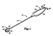
- the stethoscope 10 illustrated in Figure 1 consists of a chestpiece 12, or stethoscope head, a headpiece 14 and a connecting tube 16.
- the headpiece 14 has two eartips 18 and 20 adapted to fit in the ears of a user, typically a physician or other medical professional.
- the sound transmission system of stethoscope 10 may be entirely acoustic as is well known in the art. However, it is also contemplated that the sound transmission system of stethoscope 10 could also be electronic. In this situation, an acoustic to electronic transducer, a microphone, would be located along the acoustic sound transmission path, typically in or very near the chestpiece 12, and even more typically in the chestpiece 12 positioned in a shallow cone near the bottom surface (not shown in Figure 1) of the chestpiece 12 so as to be near the source of auscultatory sounds. Electronic means would then typically amplify, or otherwise process, the electrical signal.
- the electrical signal may be transmitted electrically to an electrical acoustic transducer, a speaker or speakers, typically located nearer the earpieces 22 and 24 of the stethoscope 10.
- an electrical acoustic transducer typically located nearer the earpieces 22 and 24 of the stethoscope 10.
- a stethoscope of a combination acoustic and electronic, or dual acoustic and electronic is also contemplated.
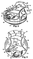
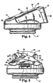
- FIG. 2, 3, 4, and 5 shows perspective, top left side and front views of the illustrative stethoscope chestpiece.
- the bottom surface 41 of the chestpiece 12 is adapted to be placed near the source of auscultatory sound, or, in a preferred embodiment, to contact the skin of the patient.
- Chestpiece 12 has a raised center portion 26 which is adapted to be grasped by the thumb and one of the fingers of the user, typically the thumb and middle finger.
- the top surface of raised center portion 26 preferably is sloped downward from rear to front of chestpiece 12 to form a surface which may be easily formed into the palm of the hand of the user.
- raised center portion 26 is higher, i.e., thicker, at the rear of the chestpiece 12 than at the front of the chestpiece 12.
- Indented gripping surfaces 28 and 30 of the raised center portion 26 are adapted to easily, securely and comfortably engage the gripping appendages (thumb and one or more fingers) of the user.
- Indented gripping surfaces 28 and 30 are defined by walls which are arcuate about one or more axes generally orthogonal to the bottom surface of chestpiece 12 and further are defined by the surface 32 of the chestpiece 12 opposite the bottom surface.
- the walls defining indented gripping surfaces 28 and 30 are also preferably arcuate about an axis generally parallel to the bottom surface of the chestpiece 12 to create an indented impression in the indented gripping surfaces 28 and 30 into which the thumb and fingers of the user can securely and comfortably fit.
- the walls of the indented gripping surfaces 28 and 30 are concavely curved in two directions; from the front toward the back, and from the top toward the bottom.
- the walls of the resulting indented gripping surfaces 28 and 30 are thus formed with an impression indented inwards toward the center of the chestpiece. In this manner, the indented gripping surfaces are adapted to fit the curves of the user's gripping fingers.
- each of the indented gripping surfaces 28 and 30 also includes a protruding edge 31 and 33, respectively.
- the areas formed by the indented impressions in the walls of indented gripping surfaces 28 and 30, the respective protruding edges 31 and 33 and surface 32 define left and right recesses which are adapted to receive the thumb and at least one finger of the user.
- the indented impressions of the left and right recesses formed into raised center portion 26 allow indented gripping surfaces 28 and 30 and the associated protruding edges 31 and 33 allow comfortable placement and secure gripping of the chestpiece by the user.
- the protruding edges 31 and 33 on indented gripping surfaces 28 and 30 prevent the fingers or thumb of the user from slipping upward during use and eliminate the possibility that the chestpiece will slip out of the user's grip during use.
- the flared out portions of the left and right recesses formed into raised center portion 26 allow gripping surfaces 28 and 30 to act as a physical stop which prevents the fingers or thumb of the user from sliding forward during use and eliminates the possibility of the fingers and/or thumb slipping off of the chestpiece 12.
- any of these types of slippage could result in an interruption of the monitoring of auscultatory sounds and further could result in pain and/or embarrassment to the user and/or the patient.
- the protruding edges 31 and 33 facilitate the physical stop of the user's fingers slipping upward.
- the flaring out of the indented gripping surfaces to an angle outward of directly forward in the chestpiece facilitates the physical stop of the user's fingers forward. It is preferred that this angle be at least thirty degrees from straight forward and, still further preferably, this should be at least about forty-five degrees but, for comfort, substantially less than ninety degrees from straight forward on the chestpiece 12.
- the indented gripping surfaces 28 and 30 are indented inwards to fit the curve of the user's fingers, the user is provided with tactile feedback concerning the positioning of the chestpiece in the hand. This feedback allows the user to know, understand and adjust, if necessary, the positioning of the chestpiece in the hand without having to visually perceive the chestpiece.
- the chestpiece 12 also includes at least one finger recess, such as recesses 70, 72, and 74.
- Finger recesses 70 and 74 provide rest positions for the user's index finger when it is not operating one of the operational controls 52 or 58.
- Finger recess 72 provides the user with tactile feedback concerning the location of the rotary switch 58, and can also be used as an alternative rest position. The tactile feedback provided by finger recesses 70, 72, and 74 help the user properly position the chestpiece in the hand and easily locate the operational controls without having to visually perceive the chestpiece.
- the walls of the indented gripping surfaces may be roughened, textured, or have ridges formed thereon.
- the roughened surface may be regular or irregular.
- the walls of the indented gripping surfaces 28 and 30 may be scored or impressed with a fish gill or knurled pattern, for example.
- the ergonometric chestpiece 12 has a shape which is generally circular. Further, where the shape of chestpiece 12 is generally circular, the left and right walls formed by indented gripping surfaces 28 and 30 are preferred to be cylindrically concave around axes generally orthogonal to the bottom surface.
- At least one operational control in this embodiment a push-button switch 52, is positioned on the top surface of the raised center portion 26.
- Push-button switch 52 is positioned roughly in the middle of raised center portion 26 generally forward of indented gripping surfaces 28 and 30. In this position, push-button switch 52 is easily available to be manipulated by the index finger of the user when indented gripping surfaces 28 and 30 are grasped by the user's thumb and middle finger.
- Typical uses of push-button switch 52 are to turn power to the stethoscope 10 on, or select different modes of operation of the stethoscope, for example, by selecting a different frequency response of the stethoscope.
- the push-button switch 52 is located in recess 54 on the top surface and of raised center portion 26.
- Mode indicators 62, 64, and 66 are also located within recess 54.
- Recess 54 itself is arcuate, skewing toward the outside edge of raised center portion 26 similar to the wall formed by indented gripping surface 28.
- the recess 54, push-button switch 52, and mode indicators 62, 64, and 66 are covered with a silicone resilient membrane that is semi-transparent to allow the user to view the status of the mode indicators 62, 64, and 66.
- Rotary control 58 (potentiometer) is positioned in a recess near the front edge of raised center portion 26 and chestpiece 12.
- the rotary action of switch 58 is in a plane parallel to the plane of bottom surface.
- the rotary action of switch 58 is in a plane perendicular to the plane of bottom surface, wherein the plane is positioned from the back to the front of the stethoscope chestpiece.
- push-button switch 52 may be used to control power to the stethoscope and control the mode selection of the stethoscope
- rotary switch 58 may be used to control the volume of the stethoscope 10.
- Mode indicators 62, 64 and 66 indicate the current mode in which the stethoscope is operating. All of these controls are easily accessible to and easily manipulated by the index finger of the user. The resulting chestpiece is one which can easily and comfortably be used by both right and left handed users.
- Connecting tube 16 (not shown in Figures 2, 3, 4 and 5) is coupled to chestpiece 12 at the rear of chestpiece 12 at opening 38.
- chestpiece 12 functions quite ergonometrically in use by the physician or other health care professional.
Landscapes
- Health & Medical Sciences (AREA)
- Life Sciences & Earth Sciences (AREA)
- Molecular Biology (AREA)
- General Health & Medical Sciences (AREA)
- Engineering & Computer Science (AREA)
- Biomedical Technology (AREA)
- Heart & Thoracic Surgery (AREA)
- Medical Informatics (AREA)
- Physics & Mathematics (AREA)
- Surgery (AREA)
- Animal Behavior & Ethology (AREA)
- Acoustics & Sound (AREA)
- Public Health (AREA)
- Veterinary Medicine (AREA)
- Dental Tools And Instruments Or Auxiliary Dental Instruments (AREA)
- Percussion Or Vibration Massage (AREA)
- Massaging Devices (AREA)
- Prostheses (AREA)
- Food-Manufacturing Devices (AREA)
Claims (15)
- Ergonometrisches Bruststück (12) für ein Stethoskop (10), das geeignet ist, Auskultationsgeräusche von einem Körper zu empfangen, und geeignet ist, mit einem Ohrstück für einen Benutzer gekoppelt zu werden, wobei das Bruststück geeignet ist, durch einen Daumen und mindestens einen Finger des Benutzers ergriffen zu werden;
wobei das Bruststück (12) eine Unterseite (41) hat, die allgemein eben und geeignet ist, nahe am Körper zum Empfangen der Auskultationsgeräusche angeordnet zu sein;
wobei das Bruststück (12) einen oberen Abschnitt entgegengesetzt zur Unterseite (41) hat;
wobei der obere Abschnitt einen erhöhten Mittelabschnitt (26) hat, der eine linke und eine rechte eingesenkte Greiffläche (28, 30) bildet, die Aussparungen formen, die durch die linke und rechte eingesenkte Greiffläche (28, 30) und durch eine Oberfläche (32) entgegengesetzt zur Unterseite (41) gebildet sind, wobei die linke und rechte eingesenkte Greiffläche (28, 30) geeignet sind, den Daumen bzw. den mindestens einen Finger des Benutzers aufzunehmen;
wobei die eingesenkten Greifflächen (28, 30) durch eine linke und eine rechte Wand gebildet sind, die jeweils eine konkave Oberfläche haben, die um eine Achse gebogen ist, die allgemein senkrecht zur Unterseite (41) ist; dadurch gekennzeichnet, daß
die eingesenkten Greifflächen (28, 30) ferner eine eingesenkte Höhlung haben, die um eine Achse gebogen ist, die allgemein parallel zur Unterseite (41) ist; und
die eingesenkten Greifflächen (28, 30) jeweils ferner eine vorstehende Kante (31, 33) an einer Oberseite des erhöhten Mittelabschnitts (26) haben. - Ergonometrisches Bruststück (12) nach Anspruch 1, wobei die Oberseite des erhöhten Mittelabschnitts (26) im Hinblick auf die Unterseite (41) geneigt ist, wobei die Oberseite an der Vorderseite des Bruststücks (12) näher zur Unterseite (41) als an der Rückseite des Bruststücks (12) liegt.
- Ergonometrisches Bruststück (12) nach Anspruch 1, das ferner mindestens ein Bedienelement (52, 58) aufweist, das auf dem erhöhten Mittelabschnitt (26) an einer Position angeordnet ist, die durch einen Zeigefinger des Benutzers leicht zu bedienen ist.
- Ergonometrisches Bruststück (12) nach Anspruch 3, wobei das mindestens eine Bedienelement (52, 58) auf der Oberseite des erhöhten Mittelabschnitts (26) des Bruststücks (12) angeordnet ist.
- Ergonometrisches Bruststück (12) nach Anspruch 4, wobei das mindestens eine Bedienelement (52, 58) auf dem Vorderabschnitt des erhöhten Mittelabschnitts (26) des Bruststücks (12) angeordnet ist.
- Ergonometrisches Bruststück (12) nach Anspruch 5, wobei das Bruststück (12) mit dem Ohrstück an der Rückseite des Bruststücks gekoppelt ist.
- Ergonometrisches Bruststück (12) nach Anspruch 5, wobei das Bruststück (12) mehrere Bedienelemente (52, 58) hat, die alle auf der Oberseite des erhöhten Mittelabschnitts (26) angeordnet sind, wobei die mehreren Bedienelemente (52, 58) zur Bedienung durch einen Zeigefinger des Benutzers ergonometrisch angeordnet sind.
- Ergonometrisches Bruststück (12) nach Anspruch 7, wobei die mehreren Bedienelemente (52, 58) zur Verwendung mit einer rechten Hand oder einer linken Hand des Benutzers ergonometrisch angeordnet sind.
- Ergonometrisches Bruststück (12) nach Anspruch 7, wobei jedes der mehreren Bedienelemente (52, 58) versenkt ist.
- Ergonometrisches Bruststück (12) nach Anspruch 9, das ferner ein Drehbedienelement (58) aufweist, das im Hinblick auf die Unterseite (41) eben ist und an der Vorderkante des erhöhten Mittelabschnitts (26) des Bruststücks (12) angeordnet ist, wobei das Drehbedienelement (58) die Lautstärke des Stethoskops steuern kann.
- Ergonometrisches Bruststück (12) nach Anspruch 10, wobei die mehreren Bedienelemente (52, 58) ein erstes Bedienelement aufweisen, das Strom zum Stethoskop steuern kann und den Frequenzgang des Stethoskops steuern kann.
- Ergonometrisches Bruststück (12) nach Anspruch 1, wobei die eingesenkten Greifflächen eine aufgerauhte Textur haben.
- Ergonometrisches Bruststück (12) nach Anspruch 12, wobei die eingesenkten Greifflächen (28, 30) eine regelmäßig eingekerbte Oberfläche haben.
- Ergonometrisches Bruststück (12) nach Anspruch 1, ferner mit mindestens einer Fingeraussparung (70, 72, 74), die auf der Oberseite des Bruststücks (12) angeordnet ist.
- Ergonometrisches Bruststück (12) nach Anspruch 14, wobei die Fingeraussparung (72) auf einem Vorderabschnitt der Oberseite des Bruststücks (12) angeordnet ist.
Applications Claiming Priority (3)
| Application Number | Priority Date | Filing Date | Title |
|---|---|---|---|
| US563187 | 1995-11-27 | ||
| US08/563,187 US5663532A (en) | 1995-11-27 | 1995-11-27 | Ergonometric stethoscope chestpiece |
| PCT/US1996/016937 WO1997019639A1 (en) | 1995-11-27 | 1996-10-22 | Ergonometric stethoscope chestpiece |
Publications (2)
| Publication Number | Publication Date |
|---|---|
| EP0957767A1 EP0957767A1 (de) | 1999-11-24 |
| EP0957767B1 true EP0957767B1 (de) | 2004-03-03 |
Family
ID=24249469
Family Applications (1)
| Application Number | Title | Priority Date | Filing Date |
|---|---|---|---|
| EP96938634A Expired - Lifetime EP0957767B1 (de) | 1995-11-27 | 1996-10-22 | Ergonometrischer stethoskopkopf |
Country Status (8)
| Country | Link |
|---|---|
| US (1) | US5663532A (de) |
| EP (1) | EP0957767B1 (de) |
| JP (1) | JP2000501950A (de) |
| AU (1) | AU714497B2 (de) |
| CA (1) | CA2237560C (de) |
| DE (1) | DE69631803T2 (de) |
| DK (1) | DK0957767T3 (de) |
| WO (1) | WO1997019639A1 (de) |
Families Citing this family (19)
| Publication number | Priority date | Publication date | Assignee | Title |
|---|---|---|---|---|
| US5931792A (en) * | 1997-11-06 | 1999-08-03 | 3M Innovative Properties Company | Stethoscope chestpiece |
| US6340350B1 (en) * | 2000-01-06 | 2002-01-22 | Juanita P. Simms | Transmitter/receiver stethoscope and holder therefor |
| USD477405S1 (en) | 2002-06-21 | 2003-07-15 | George Sommerfeld | Electronic stethoscope chestpiece |
| USD477874S1 (en) | 2002-06-21 | 2003-07-29 | George Sommerfeld | Electronic stethoscope |
| US9398891B2 (en) | 2005-10-20 | 2016-07-26 | Tiba Medical, Inc. | Multiple communication interface medical examination apparatus, system, and/or method |
| WO2007047929A2 (en) * | 2005-10-20 | 2007-04-26 | Tiba Medical, Inc. | Medical examination apparatus, system, and/or method |
| USD589144S1 (en) | 2007-03-15 | 2009-03-24 | Merat Bagha | Medical device |
| US7866437B2 (en) * | 2008-09-30 | 2011-01-11 | Tgmdvm, Inc. | Stethoscope with one-handed operation |
| US20110088964A1 (en) * | 2008-09-30 | 2011-04-21 | Tgmdvm, Inc. | Stethoscope Having An Elliptical Headpiece And Amplified Earpieces |
| JP2017060667A (ja) * | 2015-09-25 | 2017-03-30 | パイオニア株式会社 | 生体音取得装置のグリップ |
| CN106037790A (zh) * | 2016-05-31 | 2016-10-26 | 成都天奥电子股份有限公司 | 一种无线听诊装置 |
| WO2019058191A1 (en) * | 2017-09-19 | 2019-03-28 | 3M Innovative Properties Company | ERGONOMIC PECTORAL PIECE |
| USD858759S1 (en) | 2017-09-19 | 2019-09-03 | 3M Innovative Properties Company | Stethoscope chestpiece |
| US11896285B2 (en) | 2018-03-14 | 2024-02-13 | Gyrus Acmi, Inc. | Device with movable buttons or switches and visual indicator |
| JP7206928B2 (ja) * | 2019-01-11 | 2023-01-18 | オムロンヘルスケア株式会社 | 生体音測定装置 |
| JP7135872B2 (ja) | 2019-01-11 | 2022-09-13 | オムロンヘルスケア株式会社 | 生体音測定装置 |
| JP7230516B2 (ja) | 2019-01-11 | 2023-03-01 | オムロンヘルスケア株式会社 | 生体音測定装置 |
| US11361918B2 (en) | 2019-03-25 | 2022-06-14 | Gyrus Acmi, Inc. | Device with movable buttons or switches and tactile identifier |
| JP2023119223A (ja) * | 2022-02-16 | 2023-08-28 | オンキヨー株式会社 | 聴診器 |
Family Cites Families (22)
| Publication number | Priority date | Publication date | Assignee | Title |
|---|---|---|---|---|
| US3288246A (en) * | 1966-11-29 | Stethoscope with improved eotatable binaural couplings | ||
| US3275099A (en) * | 1966-09-27 | Stethoscope ear tube mounting | ||
| US3108652A (en) * | 1960-06-16 | 1963-10-29 | Cardiosonics Medical Instr Co | Stethoscope |
| US3339667A (en) * | 1966-08-02 | 1967-09-05 | Propper Mfg Company Inc | Stethoscope |
| US3472335A (en) * | 1968-01-02 | 1969-10-14 | Allen Medical Instr Corp | Dual stethoscope microphone with switch-tube valve |
| US4212368A (en) * | 1978-03-13 | 1980-07-15 | Allen Derek R | Angularly related dual stethoscope head |
| US4254302A (en) * | 1979-06-05 | 1981-03-03 | Walshe James C | Electronic stethoscope |
| US4440258A (en) * | 1982-05-12 | 1984-04-03 | Minnesota Mining & Manufacturing Company | Tunable stethoscope |
| US4475619B1 (en) * | 1983-03-24 | 1994-05-10 | Minnesota Mining & Mfg | Stethoscope with floating diaphragm |
| US4569413A (en) * | 1983-05-09 | 1986-02-11 | Allen Derek R | Enhanced audiotransmission stethoscope |
| US4852684A (en) * | 1987-12-16 | 1989-08-01 | Minnesota Mining And Manufacturing Company | Compressible ear tip |
| US4913259A (en) * | 1987-12-16 | 1990-04-03 | Minnesota Mining And Manufacturing Company | Compressible ear tip |
| US4928786A (en) * | 1989-04-20 | 1990-05-29 | Allen Derek R | Self-sealing dual stethoscope head |
| USD323394S (en) | 1989-07-28 | 1992-01-21 | Minnesota Mining And Manufacturing Company | Stethoscope chestpiece |
| US4995473A (en) * | 1989-12-21 | 1991-02-26 | Minnesota Mining And Manufacturing Company | Stethoscope with diaphragm head adapter |
| US5204500A (en) * | 1991-02-20 | 1993-04-20 | Minnesota Mining And Manufacturing Company | Ergonometric stethoscope chestpiece |
| USD337381S (en) | 1991-02-20 | 1993-07-13 | Minnesota Mining And Manufacturing Company | Ergonometric stethoscope chestpiece |
| US5288953A (en) * | 1992-04-29 | 1994-02-22 | Welch Allyn, Inc. | Compressible stethoscope ear tip |
| USD338269S (en) | 1992-11-06 | 1993-08-10 | Minnesota Mining And Manufacturing Company | Ergonometric stethoscope chestpiece |
| US5367575A (en) * | 1992-12-16 | 1994-11-22 | Minnesota Mining And Manufacturing Company | Electronic stethoscope having battery carriage |
| US5347583A (en) * | 1992-12-16 | 1994-09-13 | Minnesota Mining And Manufacturing Company | Electronic stethoscope having binaural earpiece |
| USD353196S (en) | 1993-05-28 | 1994-12-06 | Gary Savage | Stethoscope head |
-
1995
- 1995-11-27 US US08/563,187 patent/US5663532A/en not_active Expired - Fee Related
-
1996
- 1996-10-22 AU AU75965/96A patent/AU714497B2/en not_active Ceased
- 1996-10-22 CA CA002237560A patent/CA2237560C/en not_active Expired - Fee Related
- 1996-10-22 WO PCT/US1996/016937 patent/WO1997019639A1/en not_active Ceased
- 1996-10-22 DE DE69631803T patent/DE69631803T2/de not_active Expired - Fee Related
- 1996-10-22 EP EP96938634A patent/EP0957767B1/de not_active Expired - Lifetime
- 1996-10-22 JP JP9516124A patent/JP2000501950A/ja not_active Ceased
- 1996-10-22 DK DK96938634T patent/DK0957767T3/da active
Also Published As
| Publication number | Publication date |
|---|---|
| DK0957767T3 (da) | 2004-07-12 |
| JP2000501950A (ja) | 2000-02-22 |
| DE69631803T2 (de) | 2005-01-27 |
| AU7596596A (en) | 1997-06-19 |
| WO1997019639A1 (en) | 1997-06-05 |
| US5663532A (en) | 1997-09-02 |
| CA2237560A1 (en) | 1997-06-05 |
| CA2237560C (en) | 2004-09-21 |
| AU714497B2 (en) | 2000-01-06 |
| DE69631803D1 (de) | 2004-04-08 |
| EP0957767A1 (de) | 1999-11-24 |
Similar Documents
| Publication | Publication Date | Title |
|---|---|---|
| EP0957767B1 (de) | Ergonometrischer stethoskopkopf | |
| EP0500279B1 (de) | Ergonometrischer Stethoskop-Kopf | |
| US8092396B2 (en) | Electronic auscultation device | |
| US9398891B2 (en) | Multiple communication interface medical examination apparatus, system, and/or method | |
| US6202784B1 (en) | Stethoscope having a light source | |
| US7841445B2 (en) | Dual-sensor stethoscope with electronic sensor | |
| US6340350B1 (en) | Transmitter/receiver stethoscope and holder therefor | |
| US7881795B2 (en) | Method of patient initiated electro-cardiogram storage, status query and therapy activation | |
| WO1998052503A1 (en) | Ear phone assembly for use with a hearing screener | |
| US5913309A (en) | Disposable element for use with a hearing screener | |
| WO2003013402A1 (en) | A tongue and jaw operable control apparatus | |
| KR102294077B1 (ko) | 의료용 의사 소통 장치 | |
| US20210373593A1 (en) | Ear physiological wearable device | |
| KR102662346B1 (ko) | 근력저하 장애인용 웨어러블 호출장치 | |
| US11369336B2 (en) | Ergonomic chestpiece | |
| CN211723224U (zh) | 一种用于疫情电子听诊器 | |
| JPH0655602U (ja) | 心摶数測定器 | |
| CN217659870U (zh) | 一种血氧监测保护套 | |
| JP2537711B2 (ja) | 心電図計測伝送機能付き電話機 | |
| KR101770975B1 (ko) | 청진기 | |
| CN118075649A (zh) | 一种骨传导发声单元及头戴设备 | |
| JP2000013897A (ja) | 介護用補聴器 |
Legal Events
| Date | Code | Title | Description |
|---|---|---|---|
| PUAI | Public reference made under article 153(3) epc to a published international application that has entered the european phase |
Free format text: ORIGINAL CODE: 0009012 |
|
| 17P | Request for examination filed |
Effective date: 19980612 |
|
| AK | Designated contracting states |
Kind code of ref document: A1 Designated state(s): BE DE DK FR GB IT NL |
|
| 17Q | First examination report despatched |
Effective date: 20020822 |
|
| GRAH | Despatch of communication of intention to grant a patent |
Free format text: ORIGINAL CODE: EPIDOS IGRA |
|
| GRAS | Grant fee paid |
Free format text: ORIGINAL CODE: EPIDOSNIGR3 |
|
| GRAA | (expected) grant |
Free format text: ORIGINAL CODE: 0009210 |
|
| AK | Designated contracting states |
Kind code of ref document: B1 Designated state(s): BE DE DK FR GB IT NL |
|
| PG25 | Lapsed in a contracting state [announced via postgrant information from national office to epo] |
Ref country code: NL Free format text: LAPSE BECAUSE OF FAILURE TO SUBMIT A TRANSLATION OF THE DESCRIPTION OR TO PAY THE FEE WITHIN THE PRESCRIBED TIME-LIMIT Effective date: 20040303 Ref country code: BE Free format text: LAPSE BECAUSE OF FAILURE TO SUBMIT A TRANSLATION OF THE DESCRIPTION OR TO PAY THE FEE WITHIN THE PRESCRIBED TIME-LIMIT Effective date: 20040303 |
|
| REG | Reference to a national code |
Ref country code: GB Ref legal event code: FG4D |
|
| REF | Corresponds to: |
Ref document number: 69631803 Country of ref document: DE Date of ref document: 20040408 Kind code of ref document: P |
|
| REG | Reference to a national code |
Ref country code: DK Ref legal event code: T3 |
|
| NLV1 | Nl: lapsed or annulled due to failure to fulfill the requirements of art. 29p and 29m of the patents act | ||
| PGFP | Annual fee paid to national office [announced via postgrant information from national office to epo] |
Ref country code: GB Payment date: 20041013 Year of fee payment: 9 |
|
| PGFP | Annual fee paid to national office [announced via postgrant information from national office to epo] |
Ref country code: FR Payment date: 20041020 Year of fee payment: 9 |
|
| PGFP | Annual fee paid to national office [announced via postgrant information from national office to epo] |
Ref country code: DK Payment date: 20041021 Year of fee payment: 9 |
|
| ET | Fr: translation filed | ||
| PGFP | Annual fee paid to national office [announced via postgrant information from national office to epo] |
Ref country code: DE Payment date: 20041130 Year of fee payment: 9 |
|
| PLBE | No opposition filed within time limit |
Free format text: ORIGINAL CODE: 0009261 |
|
| STAA | Information on the status of an ep patent application or granted ep patent |
Free format text: STATUS: NO OPPOSITION FILED WITHIN TIME LIMIT |
|
| 26N | No opposition filed |
Effective date: 20041206 |
|
| PG25 | Lapsed in a contracting state [announced via postgrant information from national office to epo] |
Ref country code: IT Free format text: LAPSE BECAUSE OF NON-PAYMENT OF DUE FEES Effective date: 20051022 Ref country code: GB Free format text: LAPSE BECAUSE OF NON-PAYMENT OF DUE FEES Effective date: 20051022 |
|
| PG25 | Lapsed in a contracting state [announced via postgrant information from national office to epo] |
Ref country code: DK Free format text: LAPSE BECAUSE OF NON-PAYMENT OF DUE FEES Effective date: 20051031 |
|
| PG25 | Lapsed in a contracting state [announced via postgrant information from national office to epo] |
Ref country code: DE Free format text: LAPSE BECAUSE OF NON-PAYMENT OF DUE FEES Effective date: 20060503 |
|
| REG | Reference to a national code |
Ref country code: DK Ref legal event code: EBP |
|
| GBPC | Gb: european patent ceased through non-payment of renewal fee |
Effective date: 20051022 |
|
| PG25 | Lapsed in a contracting state [announced via postgrant information from national office to epo] |
Ref country code: FR Free format text: LAPSE BECAUSE OF NON-PAYMENT OF DUE FEES Effective date: 20060630 |
|
| REG | Reference to a national code |
Ref country code: FR Ref legal event code: ST Effective date: 20060630 |