EP0957331B1 - Winkelmesslehre für scharfgeschliffene Werkzeuge - Google Patents
Winkelmesslehre für scharfgeschliffene Werkzeuge Download PDFInfo
- Publication number
- EP0957331B1 EP0957331B1 EP19990201389 EP99201389A EP0957331B1 EP 0957331 B1 EP0957331 B1 EP 0957331B1 EP 19990201389 EP19990201389 EP 19990201389 EP 99201389 A EP99201389 A EP 99201389A EP 0957331 B1 EP0957331 B1 EP 0957331B1
- Authority
- EP
- European Patent Office
- Prior art keywords
- frame
- grinding wheel
- angle
- grinding
- periphery
- Prior art date
- Legal status (The legal status is an assumption and is not a legal conclusion. Google has not performed a legal analysis and makes no representation as to the accuracy of the status listed.)
- Expired - Lifetime
Links
- 238000005259 measurement Methods 0.000 claims 2
- 229910000831 Steel Inorganic materials 0.000 description 2
- 239000010959 steel Substances 0.000 description 2
- 239000002023 wood Substances 0.000 description 1
Images
Classifications
-
- G—PHYSICS
- G01—MEASURING; TESTING
- G01B—MEASURING LENGTH, THICKNESS OR SIMILAR LINEAR DIMENSIONS; MEASURING ANGLES; MEASURING AREAS; MEASURING IRREGULARITIES OF SURFACES OR CONTOURS
- G01B3/00—Measuring instruments characterised by the use of mechanical techniques
- G01B3/56—Gauges for measuring angles or tapers, e.g. conical calipers
Definitions
- the present invention concerns an angle gauge used when grinding the lip of sharp-edged tools according to the introduction to claim 1.
- the lip of sharp-edged tools of various types has the correct cutting angle in order for the tool to function in the correct way and with good control of its movement without the lip being damaged.
- the correct cutting angle naturally depends on the quality of the steel, the type of tool, the hardness of the wood and how hard one works with the tool. Experience of these variables determines the angle that is correct for each occasion.
- an angle gauge has been devised with which it is possible to rig the tool at the grinding wheel and its holder for grinding to the correct, chosen cutting angle, and with which it is possible to even measure cutting angles found on the tool.
- the adjustment of the tool at the grinding wheel holder to attain the correct cutting angle can be made independent of the diameter of the grinding wheel within, of course, reasonable limits.
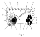
- Fig. 1 shows the angle gauge according to the invention seen from the side
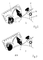
- Fig. 2 shows a tool rigged for grinding with a certain diameter of grinding wheel
- Fig. 3 shows a situation equivalent to that shown in Fig. 2 but with a different diameter of grinding wheel
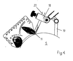
- Fig. 4 shows the set-up during the grinding of a gouge.
- the angle gauge according to the invention includes a frame 1 with a certain longitudinal extension and a thickness of 3-5 millimetres, for example.
- a first device in the form of a cam plate 2 is arranged at one end of the frame.
- Cam plate 2 is arranged to rotate around point 3 on the frame 1.
- cam plate 2 is provided with a slot 4 with its centre of curvature at 3.
- a locking screw 5 extends through the slot 4, with whose help the cam plate can be locked in position against the frame 1 at different angles of rotation.
- the edge of the frame 1, which is pointed towards the grinding wheel when the invention is in use, is convex and the cam plate 2 extends out from this edge 6 of the frame 1.
- a second device in the form of an elongated body 7 is arranged at the other end of the frame 1.
- the elongated body 7 is arranged to be rotatable and attached to the frame 1 around point 8.
- Body 7 also has a slot 9 with its centre of curvature at 8.
- a locking screw 10 extends through the slot 8, with whose help the elongated body 7 can be locked in position against the frame 1 at different angles of rotation.
- the elongated body 7 extends out from the edge 6 of frame 1 and has a flat edge 11 at its outer end.
- the cam plate 2 and the elongated body 7 are provided with sharp indicating points 12 and 13 respectively and the frame is provided with scales 14 and 15 respectively.
- Scale 14 for cam plate 2 is graduated from 150 to 250 millimetres and refers to the diameter of the grinding wheel in question.
- Scale 15 gives the intended cutting angle.
- frame 1 is provided with a number of sharp pointed notches 16 with different bottom angles for easy checking of the cutting angle of a tool.
- Fig. 2 thus shows the grinding of a steel tool 17 clamped in a jig 18 held by a universal support 19.
- the cam plate 2 is adjusted for grinding with a grinding wheel S with a diameter of 180 millimetres and the body 7 that determines the angle of the cutting angle that is to be ground is adjusted to 25°.
- Fig. 3 shows grinding with a 25° cutting angle but with a grinding wheel of 250 millimetres diameter.
- Fig. 4 shows the equivalent grinding of a gouge 20 to an angle of 45° with a grinding wheel of 225 millimetres diameter.
- the jig 18 is of another type than that shown in Figs. 2 and 3 and the gouge is tilted around its longitudinal axis during the grinding.
- the correct cutting angle can always be set with the help of the device 7.
- the frame 1 with the devices 2 and 7 is brought to abut the grinding wheel S, as shown, with the diameter of the grinding wheel set on cam plate 2 and with the cutting angle set on body 7.
- the corner edge 21 ( Fig. 1 ) of the flat edge 11 of this body that lies closest to cam plate 2 thereby abuts the grinding wheel S.
- the tool 17 (20) is now rigged in the grinding wheel support via the jig 18 so that its upper side coincides with the flat edge 11 in the manner shown in Figs. 2-4 . Following this, the angle gauge is removed and the grinding begins. The cutting angle can be checked easily afterwards with the help of the pre-set angle gauge.
- the cam plate is provided with a window 22 in which a scale graduated in inches is visible.
Landscapes
- Physics & Mathematics (AREA)
- General Physics & Mathematics (AREA)
- Finish Polishing, Edge Sharpening, And Grinding By Specific Grinding Devices (AREA)
- Knives (AREA)
- Length-Measuring Instruments Using Mechanical Means (AREA)
- Constituent Portions Of Griding Lathes, Driving, Sensing And Control (AREA)
- Grinding And Polishing Of Tertiary Curved Surfaces And Surfaces With Complex Shapes (AREA)
Claims (4)
- Winkellehre zur Verwendung beim Schleifen der Schneide von scharfkantigen Werkzeugen, die einem Rahmen (1) mit einer Längsausdehnung aufweist, dadurch gekennzeichnet, dass eine verstellbare erste Vorrichtung (2) an einem Ende des Rahmens auf dem Rahmen angebracht ist, die dazu vorgesehen ist, während der Messung auf dem Umfang des Schleifrads (S) aufzuliegen, und die durch Verstellen den Abstand zwischen dem genannten einen Ende und dem Umfang des Schleifrads verändert, und dass eine verstellbare, drehbare zweite Vorrichtung (7) am anderen Ende des Rahmens angebracht ist und eine flache Kante (11) aufweist, die zum Umfang des Schleifrads weist und die während der Messung mit der der ersten Vorrichtung zugewandten Eckkante am Umfang des Schleifrads derart anliegt, dass die flache Kante (11) einen Winkel mit dem Umfang des Schleifrads bildet, wobei dieser Winkel den Schneidwinkel definiert.
- Winkellehre nach Anspruch 1, dadurch gekennzeichnet, dass die erste Vorrichtung (2) eine drehbare Nockenscheibe aufweist, die gegenüber dem Rahmen (1) arretierbar ist.
- Winkellehre nach Anspruch 1 oder 2, dadurch gekennzeichnet, dass die zweite Vorrichtung (7) die Form eines länglichen Körpers aufweist, der gegenüber dem Rahmen arretierbar ist und ein Ende aufweist, das vom Rahmen nach aussen weist und die flache Kante (11) bildet.
- Winkellehre nach einem der vorstehenden Ansprüche, dadurch gekennzeichnet, dass die erste Vorrichtung (2) und die zweite Vorrichtung (7) mit spitzen Zeigern (12, 13) ausgeführt sind, die mit auf dem Rahmen angebrachten Skalen (14, 15) zusammenwirken.
Applications Claiming Priority (2)
| Application Number | Priority Date | Filing Date | Title |
|---|---|---|---|
| SE9801670A SE510945C2 (sv) | 1998-05-13 | 1998-05-13 | Vinkelmätare vid slipning av eggverktyg |
| SE9801670 | 1998-05-13 |
Publications (3)
| Publication Number | Publication Date |
|---|---|
| EP0957331A2 EP0957331A2 (de) | 1999-11-17 |
| EP0957331A3 EP0957331A3 (de) | 2001-04-11 |
| EP0957331B1 true EP0957331B1 (de) | 2008-07-23 |
Family
ID=20411289
Family Applications (1)
| Application Number | Title | Priority Date | Filing Date |
|---|---|---|---|
| EP19990201389 Expired - Lifetime EP0957331B1 (de) | 1998-05-13 | 1999-05-04 | Winkelmesslehre für scharfgeschliffene Werkzeuge |
Country Status (5)
| Country | Link |
|---|---|
| EP (1) | EP0957331B1 (de) |
| JP (1) | JP2000002502A (de) |
| CA (1) | CA2271172A1 (de) |
| DE (1) | DE69939140D1 (de) |
| SE (1) | SE510945C2 (de) |
Cited By (2)
| Publication number | Priority date | Publication date | Assignee | Title |
|---|---|---|---|---|
| CN108871161A (zh) * | 2018-06-25 | 2018-11-23 | 奇瑞汽车股份有限公司 | 一种用于小平面角度检测的检具总成及其使用方法 |
| WO2023169834A1 (en) | 2022-03-07 | 2023-09-14 | Tormek Ab | A grinding angle setting device, a grinding system and a method of setting a grinding angle |
Families Citing this family (27)
| Publication number | Priority date | Publication date | Assignee | Title |
|---|---|---|---|---|
| US7303582B2 (en) | 2003-03-21 | 2007-12-04 | Advanced Medical Optics, Inc. | Foldable angle-fixated intraocular lens |
| SE529606C2 (sv) | 2006-02-10 | 2007-10-02 | Tj Utveckling Ab | Verktygsinställare för en slipmaskin |
| US7993398B2 (en) | 2007-04-24 | 2011-08-09 | Abbott Medical Optics Inc. | Angle indicator for capsular bag size measurement |
| US8002827B2 (en) | 2007-04-24 | 2011-08-23 | Abbott Medical Optics Inc. | Systems and methods for ocular measurements |
| US9216080B2 (en) | 2007-08-27 | 2015-12-22 | Amo Groningen B.V. | Toric lens with decreased sensitivity to cylinder power and rotation and method of using the same |
| US8974526B2 (en) | 2007-08-27 | 2015-03-10 | Amo Groningen B.V. | Multizonal lens with extended depth of focus |
| ATE523810T1 (de) | 2008-02-15 | 2011-09-15 | Amo Regional Holdings | System, brillenglas und verfahren zur erweiterung der fokustiefe |
| US8439498B2 (en) | 2008-02-21 | 2013-05-14 | Abbott Medical Optics Inc. | Toric intraocular lens with modified power characteristics |
| US8862447B2 (en) | 2010-04-30 | 2014-10-14 | Amo Groningen B.V. | Apparatus, system and method for predictive modeling to design, evaluate and optimize ophthalmic lenses |
| CA2784782C (en) | 2009-12-18 | 2018-02-27 | Hendrik A. Weeber | Limited echelette lens, systems and methods |
| EP3330776A1 (de) | 2010-12-01 | 2018-06-06 | AMO Groningen B.V. | Multifokale linse mit optischer leistungsverstärkungsprogression sowie system und verfahren zur bereitstellung davon |
| US8365427B2 (en) | 2011-04-22 | 2013-02-05 | Stuart Batty | Grinding angle gauge and holder |
| EP2928413B1 (de) | 2012-12-04 | 2019-08-14 | AMO Groningen B.V. | Linsen, systeme und verfahren zur personalisierten binokularen presbyopiekorrektur |
| CN103033120B (zh) * | 2012-12-26 | 2015-03-25 | 马鞍山市恒利达机械刀片有限公司 | 一种制造刀口角度检测工具的方法 |
| EP3413840A1 (de) | 2016-02-09 | 2018-12-19 | AMO Groningen B.V. | Gleitsichtintraokularlinse und verfahren zur verwendung und herstellung |
| US11123178B2 (en) | 2016-03-23 | 2021-09-21 | Johnson & Johnson Surgical Vision, Inc. | Power calculator for an ophthalmic apparatus with corrective meridians having extended tolerance or operation band |
| AU2017238517B2 (en) | 2016-03-23 | 2021-11-11 | Johnson & Johnson Surgical Vision, Inc. | Ophthalmic apparatus with corrective meridians having extended tolerance band |
| WO2018078439A2 (en) | 2016-10-25 | 2018-05-03 | Amo Groningen B.V. | Realistic eye models to design and evaluate intraocular lenses for a large field of view |
| US10739227B2 (en) | 2017-03-23 | 2020-08-11 | Johnson & Johnson Surgical Vision, Inc. | Methods and systems for measuring image quality |
| WO2019106067A1 (en) | 2017-11-30 | 2019-06-06 | Amo Groningen B.V. | Intraocular lenses that improve post-surgical spectacle independent and methods of manufacturing thereof |
| DE202019101756U1 (de) | 2019-03-27 | 2019-04-04 | Janfried Seeburger | Schleifhilfe und Werkzeugmaschine mit Schleifhilfe |
| US11886046B2 (en) | 2019-12-30 | 2024-01-30 | Amo Groningen B.V. | Multi-region refractive lenses for vision treatment |
| US11279003B1 (en) * | 2020-01-03 | 2022-03-22 | Angle Pro Sharpener LLC | Knife sharpeners with angle gauge |
| USD928634S1 (en) | 2020-01-24 | 2021-08-24 | Rhineland Cutlery, Llc | Angle gauge |
| EP4333685B1 (de) | 2021-05-05 | 2026-01-14 | AMO Groningen B.V. | Ringhalometersystem und verfahren zur quantifizierung von dysphotopsien |
| US12544218B2 (en) | 2021-12-03 | 2026-02-10 | Amo Groningen B.V. | Lenses having multi-ring design for vision treatment |
| CN116276342A (zh) * | 2023-03-07 | 2023-06-23 | 上海沃特华本半导体科技有限公司 | 一种多角度调节的刀具研磨机 |
Family Cites Families (3)
| Publication number | Priority date | Publication date | Assignee | Title |
|---|---|---|---|---|
| US5172484A (en) * | 1991-05-16 | 1992-12-22 | Thomas Triola | Angle measuring device for peripheral grinding wheels with tool rests |
| GB9227008D0 (en) * | 1992-12-24 | 1993-02-17 | Donnell Michael O | Grinding jig |
| SE510362C2 (sv) * | 1995-11-28 | 1999-05-17 | Tormek Ab | Slipjigg för slipning av skölpjärn |
-
1998
- 1998-05-13 SE SE9801670A patent/SE510945C2/sv unknown
-
1999
- 1999-05-04 EP EP19990201389 patent/EP0957331B1/de not_active Expired - Lifetime
- 1999-05-04 DE DE69939140T patent/DE69939140D1/de not_active Expired - Lifetime
- 1999-05-06 CA CA 2271172 patent/CA2271172A1/en not_active Abandoned
- 1999-05-13 JP JP13332899A patent/JP2000002502A/ja active Pending
Cited By (2)
| Publication number | Priority date | Publication date | Assignee | Title |
|---|---|---|---|---|
| CN108871161A (zh) * | 2018-06-25 | 2018-11-23 | 奇瑞汽车股份有限公司 | 一种用于小平面角度检测的检具总成及其使用方法 |
| WO2023169834A1 (en) | 2022-03-07 | 2023-09-14 | Tormek Ab | A grinding angle setting device, a grinding system and a method of setting a grinding angle |
Also Published As
| Publication number | Publication date |
|---|---|
| CA2271172A1 (en) | 1999-11-13 |
| JP2000002502A (ja) | 2000-01-07 |
| SE9801670L (sv) | 1999-07-12 |
| EP0957331A2 (de) | 1999-11-17 |
| EP0957331A3 (de) | 2001-04-11 |
| SE510945C2 (sv) | 1999-07-12 |
| DE69939140D1 (de) | 2008-09-04 |
| SE9801670D0 (sv) | 1998-05-13 |
Similar Documents
| Publication | Publication Date | Title |
|---|---|---|
| EP0957331B1 (de) | Winkelmesslehre für scharfgeschliffene Werkzeuge | |
| US6532679B2 (en) | Fixture for a table saw | |
| US4406069A (en) | Perpendicularity indicator for machine tool and method of operation | |
| US6189225B1 (en) | Angle gauge for grinding sharp-edged tools | |
| US4531296A (en) | Device for marking out workpieces | |
| US5758558A (en) | Precision measuring apparatus for locating workpieces for work operations | |
| US4969782A (en) | Key blank adaptor | |
| US6817111B1 (en) | Alignment tool for positioning a cutting tool of a shaping machine | |
| US4270315A (en) | Fixture for holding a twist drill to be reground | |
| US3482325A (en) | Gauge for positioning drills relative to a grinding wheel | |
| US2521231A (en) | Vise and jig | |
| US4520599A (en) | Drill bit sharpener | |
| US4088060A (en) | Key cutting device | |
| US2887833A (en) | Tool grinding jig | |
| US20120266473A1 (en) | Grinding Angle Gauge and Holder | |
| CN111220045B (zh) | 一种具有角度刻度的麻花钻检测装置及检测方法 | |
| US4519143A (en) | Sheet metal bending position marker system | |
| US20100248594A1 (en) | Setup tool for grinder sharpening jigs | |
| US3447245A (en) | Method for cutting radii on workpiece | |
| US4161821A (en) | Scribing tool for marking wall panels for cutting to fit the contour of a wall corner | |
| US4376341A (en) | Tool-to-workpiece angle gauge | |
| KR101801684B1 (ko) | 드릴 연삭 지그 및 이를 이용한 드릴 연삭 방법 | |
| US5961256A (en) | Rough boring tool having means to show microadjustable boring hole diameter machining quantity | |
| US4626151A (en) | Tool alignment gauge | |
| US6964208B2 (en) | Measuring device for wood cutting tool |
Legal Events
| Date | Code | Title | Description |
|---|---|---|---|
| PUAI | Public reference made under article 153(3) epc to a published international application that has entered the european phase |
Free format text: ORIGINAL CODE: 0009012 |
|
| 17P | Request for examination filed |
Effective date: 19990504 |
|
| AK | Designated contracting states |
Kind code of ref document: A2 Designated state(s): DE FR GB IT |
|
| AX | Request for extension of the european patent |
Free format text: AL;LT;LV;MK;RO;SI |
|
| PUAL | Search report despatched |
Free format text: ORIGINAL CODE: 0009013 |
|
| AK | Designated contracting states |
Kind code of ref document: A3 Designated state(s): AT BE CH CY DE DK ES FI FR GB GR IE IT LI LU MC NL PT SE |
|
| AX | Request for extension of the european patent |
Free format text: AL;LT;LV;MK;RO;SI |
|
| RIC1 | Information provided on ipc code assigned before grant |
Free format text: 7G 01B 3/56 A, 7B 24B 3/36 B |
|
| AKX | Designation fees paid |
Free format text: DE FR GB IT |
|
| GRAP | Despatch of communication of intention to grant a patent |
Free format text: ORIGINAL CODE: EPIDOSNIGR1 |
|
| GRAS | Grant fee paid |
Free format text: ORIGINAL CODE: EPIDOSNIGR3 |
|
| GRAA | (expected) grant |
Free format text: ORIGINAL CODE: 0009210 |
|
| AK | Designated contracting states |
Kind code of ref document: B1 Designated state(s): DE FR GB IT |
|
| REG | Reference to a national code |
Ref country code: GB Ref legal event code: FG4D |
|
| REF | Corresponds to: |
Ref document number: 69939140 Country of ref document: DE Date of ref document: 20080904 Kind code of ref document: P |
|
| PLBE | No opposition filed within time limit |
Free format text: ORIGINAL CODE: 0009261 |
|
| STAA | Information on the status of an ep patent application or granted ep patent |
Free format text: STATUS: NO OPPOSITION FILED WITHIN TIME LIMIT |
|
| 26N | No opposition filed |
Effective date: 20090424 |
|
| PG25 | Lapsed in a contracting state [announced via postgrant information from national office to epo] |
Ref country code: IT Free format text: LAPSE BECAUSE OF FAILURE TO SUBMIT A TRANSLATION OF THE DESCRIPTION OR TO PAY THE FEE WITHIN THE PRESCRIBED TIME-LIMIT Effective date: 20080723 |
|
| REG | Reference to a national code |
Ref country code: FR Ref legal event code: ST Effective date: 20100129 |
|
| PG25 | Lapsed in a contracting state [announced via postgrant information from national office to epo] |
Ref country code: FR Free format text: LAPSE BECAUSE OF NON-PAYMENT OF DUE FEES Effective date: 20090602 |
|
| PGFP | Annual fee paid to national office [announced via postgrant information from national office to epo] |
Ref country code: DE Payment date: 20160426 Year of fee payment: 18 |
|
| REG | Reference to a national code |
Ref country code: DE Ref legal event code: R082 Ref document number: 69939140 Country of ref document: DE Representative=s name: TERGAU & WALKENHORST PATENTANWAELTE PARTGMBB, DE |
|
| REG | Reference to a national code |
Ref country code: DE Ref legal event code: R119 Ref document number: 69939140 Country of ref document: DE |
|
| PG25 | Lapsed in a contracting state [announced via postgrant information from national office to epo] |
Ref country code: DE Free format text: LAPSE BECAUSE OF NON-PAYMENT OF DUE FEES Effective date: 20171201 |
|
| PGFP | Annual fee paid to national office [announced via postgrant information from national office to epo] |
Ref country code: GB Payment date: 20180329 Year of fee payment: 20 |
|
| REG | Reference to a national code |
Ref country code: GB Ref legal event code: PE20 Expiry date: 20190503 |
|
| PG25 | Lapsed in a contracting state [announced via postgrant information from national office to epo] |
Ref country code: GB Free format text: LAPSE BECAUSE OF EXPIRATION OF PROTECTION Effective date: 20190503 |