EP0957193B1 - Lowering sinker actuation cam set for circular knitting machines for forming standard-terry knitting and sandwich-terry knitting - Google Patents
Lowering sinker actuation cam set for circular knitting machines for forming standard-terry knitting and sandwich-terry knitting Download PDFInfo
- Publication number
- EP0957193B1 EP0957193B1 EP98108804A EP98108804A EP0957193B1 EP 0957193 B1 EP0957193 B1 EP 0957193B1 EP 98108804 A EP98108804 A EP 98108804A EP 98108804 A EP98108804 A EP 98108804A EP 0957193 B1 EP0957193 B1 EP 0957193B1
- Authority
- EP
- European Patent Office
- Prior art keywords
- sinkers
- needle cylinder
- cam
- movable cam
- knitting
- Prior art date
- Legal status (The legal status is an assumption and is not a legal conclusion. Google has not performed a legal analysis and makes no representation as to the accuracy of the status listed.)
- Expired - Lifetime
Links
Images


Classifications
-
- D—TEXTILES; PAPER
- D04—BRAIDING; LACE-MAKING; KNITTING; TRIMMINGS; NON-WOVEN FABRICS
- D04B—KNITTING
- D04B15/00—Details of, or auxiliary devices incorporated in, weft knitting machines, restricted to machines of this kind
- D04B15/32—Cam systems or assemblies for operating knitting instruments
- D04B15/34—Cam systems or assemblies for operating knitting instruments for dials
-
- D—TEXTILES; PAPER
- D04—BRAIDING; LACE-MAKING; KNITTING; TRIMMINGS; NON-WOVEN FABRICS
- D04B—KNITTING
- D04B15/00—Details of, or auxiliary devices incorporated in, weft knitting machines, restricted to machines of this kind
- D04B15/06—Sinkers
-
- D—TEXTILES; PAPER
- D04—BRAIDING; LACE-MAKING; KNITTING; TRIMMINGS; NON-WOVEN FABRICS
- D04B—KNITTING
- D04B9/00—Circular knitting machines with independently-movable needles
- D04B9/12—Circular knitting machines with independently-movable needles with provision for incorporating pile threads
Definitions
- the present invention relates to a lowering sinker actuation cam set for circular knitting machines for stocking or hosiery-making particularly for forming standard-terry knitting and sandwich-terry knitting.
- the two yarns are dispensed with a particular arrangement of the corresponding yarn guides and the lowering sinkers are actuated so that during the descent of the needles the two yarns are arranged respectively on the lower lowering plane and on the upper lowering plane of the sinkers, forming, for each needle, two loops of different length in which the longer loop provides the characteristic terry effect.
- pairs of lowering sinkers or two side-by-side sinkers are also used which are accommodated in a same radial slot of the sinker ring, each being provided with a lowering plane which is located at a different vertical level than the lowering plane of the other sinker of the same pair.
- a pair of these sinkers corresponds to a sinker with two lowering planes located at two mutually different elevations.
- the longer loops which produce the terry effect protrude on the back of the item, whilst the shorter loops are more visible on the right side.
- the shorter loops are generally formed by using a very thin yarn, usually made of helanca or other similar material, whilst the longer loops, i.e., the loops of terry, are formed with a cotton yarn.
- standard terry when patterns are formed on the item said patterns have a poor definition, owing to the fact that the shorter loops of standard terry are visible on the right side of the item between the loops of the pattern.
- terry-stitch knitting which is known as "sandwich terry"; in this terry, during the forming of the double loops, the yarn that forms the shorter loops is shifted and kept toward the back of the item, so as to interfere as little as possible with the loops of the pattern and thus allow to achieve better definition of the pattern on the right side of the item.
- This effect is achieved mainly by virtue of a particular actuation of the lowering sinkers in order to achieve, after resting the yarn on the lower lowering plane, a movement of the sinkers, or of the sinkers that have said lower lowering plane, away from the axis of the needle cylinder which correspondingly moves the yarn of the shorter loops toward the open side of the tip of the needles, i.e., on the back of the item, differently from ordinary terry knitting, in which the yarn of the shorter loops is shifted in the opposite direction.
- the movement of the sinkers away from the axis of the needle cylinder is achieved by virtue of a suitable configuration of the path which is traced by the cams and countercams and in which the heels of the lowering sinkers engage and by using special sinkers.
- sinkers are also used instead of the sinkers used for standard terry knitting.
- the aim of the present invention is to provide a set of cams for actuating the lowering sinkers for circular knitting or hosiery-making machines which allows to perform both standard-terry knitting and sandwich-terry knitting without requiring any replacement of machine parts.
- an object of the invention is to provide a cam set which allows to produce items which are composed partly of standard-terry stitches and partly of sandwich-terry stitches.
- Another object of the invention is to provide a set of cams for actuating lowering sinkers which can be installed without any problem in currently commercially available circular knitting or hosiery-making machines.
- a set of cams for actuating the lowering sinkers for circular knitting machines, for producing standard-terry stitches and sandwich-terry stitches comprising cams and countercams which form a path for the heels of the lowering sinkers which have two lowering planes arranged at mutually different elevations for at least two yarns which are dispensed at a feed of the machine to form loops of terry knitting, characterized in that it comprises, in the region of said path that corresponds to the descent of the needles of the needle cylinder to form loops of knitting with the two yarns dispensed at a feed of the machine, a cam which can move on command into two operating positions in order to produce at least one variation of the path followed by the heels of the sinkers due to said cams and countercams; said movable cam having a first profile which can be engaged by the heels of the sinkers and is suitable to produce, when said movable cam is in a first one of said two positions, a
- the cam set according to the invention comprises cams and countercams which form, as a whole, a path 1 for the heels 2a, 3a, 4a of the lowering sinkers, generally designated by the reference numerals 2, 3, 4, which are accommodated in a per se known manner within radial slots formed in the sinker ring 5, which is arranged coaxially around the needle cylinder 6 proximate to the upper end thereof.
- sinker pairs i.e., two sinkers which are arranged within the same radial slot of the sinker ring 5.
- each radial slot of the sinker ring 5 there are either a sinker 2 and a sinker 3 or a sinker 2 and a sinker 4.
- the slots of half of the sinker ring 5 accommodate sinker pairs composed of sinkers 2 and sinkers 3, whilst the slots of the other half of the sinker ring 5 accommodate sinker pairs composed of a sinker 2 and a sinker 4.
- the sinker 2 or stitch sinker, has a lowering plane 7, whilst the sinkers 3 and 4, or terry sinkers, have lowering planes 8 and 9 which are located at a higher level than the lowering plane 7 of the sinker 2.
- the lowering planes 8 and 9 of the sinkers 3 and 4 form longer loops, i.e., the characteristic terry stitches, during the descent of the needles 10 arranged in the needle cylinder 6.
- the lowering plane 7 is formed between a pair of beaks 11 and 12 of the sinker 2, in a per se known manner.
- the set of sinker actuation cams comprises, in a per se known manner, a fixed annular cam 20 which runs around the axis 6a of the needle cylinder and has an outer profile 20a provided, in a per se known manner, with portions which move gradually away from the axis 6a of the needle cylinder and with portions which gradually move closer to said axis 6a in order to produce the characteristic radial movement of the sinkers in the corresponding slots of the sinker ring 5.
- the set of actuation cams also comprises movable countercams 21, 22 and 23 which face, with their profile 21a, 22a and 23a, the profile 20a of the annular cam 20.
- the movable countercams 21, 22 and 23 are arranged at mutually different elevations so as to match the different elevation of the heels 2a, 3a and 4a of the lowering sinkers 2, 3 and 4.
- the movable countercam 21 is located at such an elevation as to interfere with the heel 2a of the sinkers 2, which is higher than the heel 3a of the sinkers 3.
- the movable countercam 22 is arranged at a lower level than the movable countercam 21, so that it can interfere both with the heel 2a of the sinkers 2 and with the heel 3a of the sinkers 3, whilst the movable countercam 23 is located below the bottom of the radial slots of the sinker ring 5, so that it can interfere only with the heel 4a of the sinkers 4 that protrudes downward from said slots.
- the movable countercams 21, 22 and 23 are packed together and are pivoted to the sinker ring 5 about an axis 30 which is parallel to the axis 6a of the needle cylinder 6, so that they can be moved from an inactive position, in which their profile 21a, 22a and 23a is spaced from the profile 20a of the annular cam 20 so as not to interfere with the corresponding heels of the sinkers 2, 3 and 4, to an active position, in which said movable countercams are closer, with their profile 21a, 22a and 23a, to the profile 20a of the annular cam 20, so as to interfere with the corresponding heels of the sinkers 2, 3 and 4.
- the movable countercams 21, 22 and 23 can oscillate individually about the axis 30, for example by means of actuators of the electromagnetic, pneumatic, mechanical type or of other conventional types, according to the requirements.
- the result is knitting with terry stitches on half of the needles of the needle cylinder 6, whilst if the movable countercams 21 and 23 are moved into the active position, the result is knitting with terry stitches on the other half of the needles of the needle cylinder 6; if the movable countercams 21, 22 and 23 are moved into the active position, the result is knitting with terry stitches on all the needles of the needle cylinder 6, except of course for any needle selections which remove some of the needles from knitting.
- the set of actuation cams comprises, in the region of the path 1 that corresponds to the descent of the needles 10 to form loops of knitting with the two yarns dispensed at a feed of the machine, a movable cam 40 which can be moved on command into two active positions in order to produce at least one variation of the path followed by the heels 2a of the sinkers 2 with respect to the path 1.
- the movable cam 40 can be moved from a first position, in which it produces, with its profile 40a, a spacing of the sinkers 2 with respect to the axis 6a of the needle cylinder and with respect to the path 1 so as to shift the yarn 60 rested on the lower lowering plane 7 of the sinkers 2 away from the axis 6a of the needle cylinder 6.
- the movable cam 40 can move from said first position to a second position in which it does not interfere with the heels 2a of the sinkers 2 but instead acts, with another second profile 40b, on the back 2b of the sinkers 2 which is directed toward the heel 2a, so as to anticipate the motion of the sinkers 2 toward the axis 6a of the needle cylinder 6 in order to shift the yarn 60, rested on the lower lowering plane 7 of the sinkers 2, toward the axis 6a of the needle cylinder, as will become apparent hereinafter.
- the movable cam 40 is partially superimposed on the annular cam 20 and is slidingly accommodated within a recess 50 formed on the upper face of the annular cam 20.
- Said recess 50 is meant to allow the sliding of the movable cam 40 in a substantially radial direction with respect to the axis 6a of the needle cylinder 6 and simultaneously to guide the movable cam 40 during said movement.
- the movable cam 40 lies on a plane which is substantially perpendicular to the axis 6a of the needle cylinder and can move, in order to pass from the first position to the second position, along a direction which is substantially radial with respect to the needle cylinder 6.
- the movable cam 40 has a first profile 40a which is formed by the side of the cam that is directed away from the axis 6a of the needle cylinder 6, i.e., faces the movable countercams 21, 22 and 23 and engages the side of the heels 2a of the sinkers 2 that is directed toward the axis 6a of the needle cylinder 6.
- the movable cam 40 also has a second profile 40b, which is formed by the side of the movable cam 40 that is directed toward the axis 6a of the needle cylinder 6 and can engage, when the movable cam 40 is moved into the second position, the back 2b of the sinker 2 that is directed toward the heel 2a.
- the first profile 40a is constituted, along the direction of motion of the sinkers with respect to the cams and countercams that actuate them, by a first portion which moves gradually away from the axis 6a of the needle cylinder 6 and is followed by a second portion which gradually approaches the axis of the needle cylinder.
- the second profile 40b of the movable cam 40 is constituted by a first portion which gradually approaches the axis 6a of the needle cylinder 6 and is followed by a second portion which gradually moves away from the axis 6a of the needle cylinder 6.
- the movable cam 40 is shaped so as to have a substantially diamond-like plan shape with rounded corners.
- the side of the countercam 21 that faces the first profile of the movable cam 40 has, at the end of the first portion of the first profile 40a of said movable cam 40, a recessed region 70 to allow the movement of the sinkers 2 away from the axis 6a of the needle cylinder 6.
- the movement of the movable cam 40 from the first position to the second position or vice versa can be performed by virtue of conventional actuators, for example actuators of the mechanical, pneumatic, electromagnetic type, etcetera.
- figures 1 and 2 relate to a circular hosiery knitting machine with four feeds or drops and that there is a movable cam 40 for each feed.
- the movable cam 40 is moved into the second position (figure 2).
- the two yarns 60 and 61 dispensed at a feed of the machine rest, when the needles 10 begin their descent, respectively on the lowering plane 7 of the sinkers 2 and on the lowering plane 8 or 9 of the sinkers 3 or 4.
- the sinkers 2 engage, with their back 2b, along the second profile of the movable cam 40, the sinkers 2 are moved toward the axis 6a of the needle cylinder 6.
- This movement also produces the movement of the yarn 60, which rests on the lowering plane 7 of the sinkers 2, toward the axis 6a of the needle cylinder and therefore the movement of said yarn 60, which constitutes the yarn by means of which the shorter loops of knitting are formed, toward the right side of the item.
- the movable cam 40 is moved into the first position (figure 1) so that the sinkers 2 are moved, after the yarn 60 has rested on the lowering plane 7, away from the axis 6a of the needle cylinder 6, consequently positioning the yarn 60, i.e., the yarn that is used to form the shorter loops, on the back of the item.
- the invention fully achieves the intended aim, since it allows to provide, with a single set of sinker actuation cams and therefore without requiring any replacement of the elements that compose the machine, both standard-terry knitting and sandwich-terry knitting.
- the materials used, as well as the dimensions, may be any according to the requirements and the state of the art.
Landscapes
- Engineering & Computer Science (AREA)
- Textile Engineering (AREA)
- Knitting Machines (AREA)
- Preliminary Treatment Of Fibers (AREA)
Description
- The present invention relates to a lowering sinker actuation cam set for circular knitting machines for stocking or hosiery-making particularly for forming standard-terry knitting and sandwich-terry knitting.
- It is known (see US-A-3937037) that knitting with terry stitches is produced in circular knitting machines for stocking or hosiery-making by using specially-provided lowering sinkers provided with two lowering planes, i.e., the planes on which the yarns rest during the descent of the needles of the needle cylinder so as to form loops of knitting, arranged at two mutually different elevations and by dispensing, at one feed of the machine, two yarns which are taken up simultaneously by the needles. The two yarns are dispensed with a particular arrangement of the corresponding yarn guides and the lowering sinkers are actuated so that during the descent of the needles the two yarns are arranged respectively on the lower lowering plane and on the upper lowering plane of the sinkers, forming, for each needle, two loops of different length in which the longer loop provides the characteristic terry effect.
- As an alternative to the use of lowering cams with two lowering planes, pairs of lowering sinkers or two side-by-side sinkers are also used which are accommodated in a same radial slot of the sinker ring, each being provided with a lowering plane which is located at a different vertical level than the lowering plane of the other sinker of the same pair. In practice, a pair of these sinkers corresponds to a sinker with two lowering planes located at two mutually different elevations.
- In this case it is also possible to actuate only the sinkers with the lower lowering plane to form normal knitting.
- Generally, in the manufacture of hosiery items the longer loops which produce the terry effect protrude on the back of the item, whilst the shorter loops are more visible on the right side. The shorter loops are generally formed by using a very thin yarn, usually made of helanca or other similar material, whilst the longer loops, i.e., the loops of terry, are formed with a cotton yarn.
- As a consequence of this fact, with conventional terry-stitch knitting, referenced hereinafter as "standard terry" for the sake of clarity, when patterns are formed on the item said patterns have a poor definition, owing to the fact that the shorter loops of standard terry are visible on the right side of the item between the loops of the pattern.
- In order to solve this problem, a particular kind of terry-stitch knitting has been devised which is known as "sandwich terry"; in this terry, during the forming of the double loops, the yarn that forms the shorter loops is shifted and kept toward the back of the item, so as to interfere as little as possible with the loops of the pattern and thus allow to achieve better definition of the pattern on the right side of the item.
- This effect is achieved mainly by virtue of a particular actuation of the lowering sinkers in order to achieve, after resting the yarn on the lower lowering plane, a movement of the sinkers, or of the sinkers that have said lower lowering plane, away from the axis of the needle cylinder which correspondingly moves the yarn of the shorter loops toward the open side of the tip of the needles, i.e., on the back of the item, differently from ordinary terry knitting, in which the yarn of the shorter loops is shifted in the opposite direction.
- The movement of the sinkers away from the axis of the needle cylinder is achieved by virtue of a suitable configuration of the path which is traced by the cams and countercams and in which the heels of the lowering sinkers engage and by using special sinkers.
- As an alternative to this solution, special sinkers are also used instead of the sinkers used for standard terry knitting.
- In any case, in order to switch from standard-terry knitting to sandwich-terry knitting, with conventional knitting or hosiery-making machine it is necessary to discontinue production and replace the cams that actuate the sinkers and replace the sinkers that engage said cams or at least the sinkers.
- For this reason, with currently commercially available machines it is not possible to produce items which are knitted partly with standard-terry knitting and partly with sandwich-terry knitting.
- This possibility, which has so far not been allowed, would instead be appreciated, since items manufactured exclusively with standard-terry stitches lead to an unsatisfactory aesthetic result in regions with patterns, whilst items formed exclusively with sandwich-terry knitting provide a better aesthetic result but are not as resistant as standard-terry items.
- The aim of the present invention is to provide a set of cams for actuating the lowering sinkers for circular knitting or hosiery-making machines which allows to perform both standard-terry knitting and sandwich-terry knitting without requiring any replacement of machine parts.
- Within the scope of this aim, an object of the invention is to provide a cam set which allows to produce items which are composed partly of standard-terry stitches and partly of sandwich-terry stitches.
- Another object of the invention is to provide a set of cams for actuating lowering sinkers which can be installed without any problem in currently commercially available circular knitting or hosiery-making machines.
- This aim, these objects and others which will become apparent hereinafter are achieved by a set of cams for actuating the lowering sinkers for circular knitting machines, for producing standard-terry stitches and sandwich-terry stitches, comprising cams and countercams which form a path for the heels of the lowering sinkers which have two lowering planes arranged at mutually different elevations for at least two yarns which are dispensed at a feed of the machine to form loops of terry knitting, characterized in that it comprises, in the region of said path that corresponds to the descent of the needles of the needle cylinder to form loops of knitting with the two yarns dispensed at a feed of the machine, a cam which can move on command into two operating positions in order to produce at least one variation of the path followed by the heels of the sinkers due to said cams and countercams; said movable cam having a first profile which can be engaged by the heels of the sinkers and is suitable to produce, when said movable cam is in a first one of said two positions, a spacing of the sinkers from the axis of the needle cylinder with respect to said path in order to move the yarn, rested on the lower lowering plane of the sinkers, away from the axis of the needle cylinder.
- Further characteristics and advantages of the invention will become apparent from the description of a preferred but not exclusive embodiment of the cam set according to the invention, illustrated only by way of non-limitative example in the accompanying drawings, wherein:
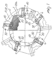
- figure 1 is a schematic top plan view of the actuation cam set according to the invention, with some elements shown in phantom lines for the sake of clarity, with the movable cam in a first position;
- figure 2 is a top plan view, similar to figure 1, of the actuation cam set according to the invention with some elements shown in phantom lines for the sake of clarity, with the movable cam in a second position;
- figure 3 is an enlarged-scale sectional view of figure 2, taken along the plane III-III, with some elements shown in phantom lines;
- figures 4 to 6 are views of three types of lowering sinker which can be used with the actuation cam set according to the invention;
- figure 7 is a bottom plan view of the movable cam;
- figure 8 is a lateral elevation view of the movable cam.
-
- With reference to the above figures, the cam set according to the invention comprises cams and countercams which form, as a whole, a
path 1 for theheels 2a, 3a, 4a of the lowering sinkers, generally designated by thereference numerals sinker ring 5, which is arranged coaxially around theneedle cylinder 6 proximate to the upper end thereof. - It should be noted that the present description is given with reference to a machine which uses sinker pairs, i.e., two sinkers which are arranged within the same radial slot of the
sinker ring 5. - More particularly, in each radial slot of the
sinker ring 5 there are either asinker 2 and asinker 3 or asinker 2 and asinker 4. In practice, the slots of half of thesinker ring 5 accommodate sinker pairs composed ofsinkers 2 andsinkers 3, whilst the slots of the other half of thesinker ring 5 accommodate sinker pairs composed of asinker 2 and asinker 4. - The
sinker 2, or stitch sinker, has a loweringplane 7, whilst thesinkers planes 8 and 9 which are located at a higher level than the loweringplane 7 of thesinker 2. - In practice, the lowering
planes 8 and 9 of thesinkers needles 10 arranged in theneedle cylinder 6. - The lowering
plane 7 is formed between a pair ofbeaks 11 and 12 of thesinker 2, in a per se known manner. - The set of sinker actuation cams comprises, in a per se known manner, a fixed
annular cam 20 which runs around theaxis 6a of the needle cylinder and has anouter profile 20a provided, in a per se known manner, with portions which move gradually away from theaxis 6a of the needle cylinder and with portions which gradually move closer to saidaxis 6a in order to produce the characteristic radial movement of the sinkers in the corresponding slots of thesinker ring 5. - The set of actuation cams also comprises
movable countercams profile 21a, 22a and 23a, theprofile 20a of theannular cam 20. - The
movable countercams heels 2a, 3a and 4a of the loweringsinkers - More particularly, the
movable countercam 21 is located at such an elevation as to interfere with the heel 2a of thesinkers 2, which is higher than theheel 3a of thesinkers 3. Themovable countercam 22 is arranged at a lower level than themovable countercam 21, so that it can interfere both with the heel 2a of thesinkers 2 and with theheel 3a of thesinkers 3, whilst themovable countercam 23 is located below the bottom of the radial slots of thesinker ring 5, so that it can interfere only with the heel 4a of thesinkers 4 that protrudes downward from said slots. - The
movable countercams sinker ring 5 about anaxis 30 which is parallel to theaxis 6a of theneedle cylinder 6, so that they can be moved from an inactive position, in which theirprofile 21a, 22a and 23a is spaced from theprofile 20a of theannular cam 20 so as not to interfere with the corresponding heels of thesinkers profile 21a, 22a and 23a, to theprofile 20a of theannular cam 20, so as to interfere with the corresponding heels of thesinkers - The
movable countercams axis 30, for example by means of actuators of the electromagnetic, pneumatic, mechanical type or of other conventional types, according to the requirements. - It should be noted that by keeping the
movable countercams sinkers sinkers 2 are actuated due to the operating position of themovable countercam 21, producing knitting with standard stitches. - If the
movable countercams needle cylinder 6, whilst if themovable countercams needle cylinder 6; if themovable countercams needle cylinder 6, except of course for any needle selections which remove some of the needles from knitting. - According to the invention, the set of actuation cams comprises, in the region of the
path 1 that corresponds to the descent of theneedles 10 to form loops of knitting with the two yarns dispensed at a feed of the machine, amovable cam 40 which can be moved on command into two active positions in order to produce at least one variation of the path followed by the heels 2a of thesinkers 2 with respect to thepath 1. - More particularly, the
movable cam 40 can be moved from a first position, in which it produces, with its profile 40a, a spacing of thesinkers 2 with respect to theaxis 6a of the needle cylinder and with respect to thepath 1 so as to shift theyarn 60 rested on thelower lowering plane 7 of thesinkers 2 away from theaxis 6a of theneedle cylinder 6. - The
movable cam 40 can move from said first position to a second position in which it does not interfere with the heels 2a of thesinkers 2 but instead acts, with another second profile 40b, on the back 2b of thesinkers 2 which is directed toward the heel 2a, so as to anticipate the motion of thesinkers 2 toward theaxis 6a of theneedle cylinder 6 in order to shift theyarn 60, rested on the lower loweringplane 7 of thesinkers 2, toward theaxis 6a of the needle cylinder, as will become apparent hereinafter. - The
movable cam 40 is partially superimposed on theannular cam 20 and is slidingly accommodated within arecess 50 formed on the upper face of theannular cam 20. Saidrecess 50 is meant to allow the sliding of themovable cam 40 in a substantially radial direction with respect to theaxis 6a of theneedle cylinder 6 and simultaneously to guide themovable cam 40 during said movement. - The
movable cam 40 lies on a plane which is substantially perpendicular to theaxis 6a of the needle cylinder and can move, in order to pass from the first position to the second position, along a direction which is substantially radial with respect to theneedle cylinder 6. - The
movable cam 40 has a first profile 40a which is formed by the side of the cam that is directed away from theaxis 6a of theneedle cylinder 6, i.e., faces themovable countercams sinkers 2 that is directed toward theaxis 6a of theneedle cylinder 6. - The
movable cam 40 also has a second profile 40b, which is formed by the side of themovable cam 40 that is directed toward theaxis 6a of theneedle cylinder 6 and can engage, when themovable cam 40 is moved into the second position, the back 2b of thesinker 2 that is directed toward the heel 2a. - The first profile 40a is constituted, along the direction of motion of the sinkers with respect to the cams and countercams that actuate them, by a first portion which moves gradually away from the
axis 6a of theneedle cylinder 6 and is followed by a second portion which gradually approaches the axis of the needle cylinder. - The second profile 40b of the
movable cam 40 is constituted by a first portion which gradually approaches theaxis 6a of theneedle cylinder 6 and is followed by a second portion which gradually moves away from theaxis 6a of theneedle cylinder 6. - In practice, the
movable cam 40 is shaped so as to have a substantially diamond-like plan shape with rounded corners. - The side of the
countercam 21 that faces the first profile of themovable cam 40 has, at the end of the first portion of the first profile 40a of saidmovable cam 40, arecessed region 70 to allow the movement of thesinkers 2 away from theaxis 6a of theneedle cylinder 6. - The movement of the
movable cam 40 from the first position to the second position or vice versa can be performed by virtue of conventional actuators, for example actuators of the mechanical, pneumatic, electromagnetic type, etcetera. - For the sake of completeness in description, it should be noted that figures 1 and 2 relate to a circular hosiery knitting machine with four feeds or drops and that there is a
movable cam 40 for each feed. - The operation of the machine provided with the set of cams for actuating the lowering sinkers according to the invention, in the production of terry knitting, is as follows.
- If one wishes to produce standard-terry knitting, the
movable cam 40 is moved into the second position (figure 2). When themovable cam 40 is in this position, the twoyarns needles 10 begin their descent, respectively on the loweringplane 7 of thesinkers 2 and on the loweringplane 8 or 9 of thesinkers sinkers 2 engage, with their back 2b, along the second profile of themovable cam 40, thesinkers 2 are moved toward theaxis 6a of theneedle cylinder 6. This movement also produces the movement of theyarn 60, which rests on the loweringplane 7 of thesinkers 2, toward theaxis 6a of the needle cylinder and therefore the movement ofsaid yarn 60, which constitutes the yarn by means of which the shorter loops of knitting are formed, toward the right side of the item. - If one wishes to form sandwich-terry knitting, the
movable cam 40 is moved into the first position (figure 1) so that thesinkers 2 are moved, after theyarn 60 has rested on the loweringplane 7, away from theaxis 6a of theneedle cylinder 6, consequently positioning theyarn 60, i.e., the yarn that is used to form the shorter loops, on the back of the item. - It should be noted that although the invention has been described with reference to a machine which uses sinker pairs in the radial slots of the
sinker ring 5, the set of cams for actuating lowering sinkers according to the invention can in any case be used with machines which use a single sinker for each radial slot of thesinker ring 5 of the type provided with two lowering planes located at two mutually different elevations. - In practice it has been found that the invention fully achieves the intended aim, since it allows to provide, with a single set of sinker actuation cams and therefore without requiring any replacement of the elements that compose the machine, both standard-terry knitting and sandwich-terry knitting.
- By virtue of this fact it is also possible to produce items composed of parts formed with standard-terry knitting, for example in regions requiring particular strength, and parts formed with sandwich-terry knitting, for example at regions with pattern stitches.
- The set of lowering sinker actuation cams thus conceived is susceptible of numerous modifications and variations, all of which are within the scope of the inventive concept; all the details may furthermore be replaced with other technically equivalent elements.
- In practice, the materials used, as well as the dimensions, may be any according to the requirements and the state of the art.
- Where technical features mentioned in any claim are followed by reference signs, those reference signs have been included for the sole purpose of increasing the intelligibility of the claims and accordingly, such reference signs do not have any limiting effect on the interpretation of each element identified by way of example by such reference signs.
Claims (10)
- A set of cams for actuating the lowering sinkers (2,3,4) for circular knitting machines, for producing standard-terry stitches and sandwich-terry stitches, comprising cams (20) and countercams (21,22,23) which form a path (1) for the heels (2a,3a,4a) of the lowering sinkers (2,3,4) which have two lowering planes (7,8,9) arranged at mutually different elevations for at least two yarns (60,61) which are dispensed at a feed of the machine to form loops of terry knitting, characterized in that it comprises, in the region of said path (1) that corresponds to the descent of the needles (10) of the needle cylinder (6) to form loops of knitting with the two yarns (60,61) dispensed at a feed of the machine, a cam (40) which can move on command into two operating positions in order to produce at least one variation of the path (1) followed by the heels (2a,3a,4a) of the sinkers (2,3,4) due to said cams (20). and countercams (21,22,23); said movable cam (40) having a first profile (40a) which can be engaged by the heels (2a,3a,4a) of the sinkers (2,3,4) and is suitable to produce, when said movable cam (40) is in a first one of said two positions, a spacing of the sinkers (2,3,4) from the axis (6a) of the needle cylinder (6) with respect to said path (1) in order to move the yarn (60,61), rested on the lower lowering plane (11) of the sinkers (2,3,4), away from the axis (6a) of the needle cylinder (6).
- A cam set according to claim 1, characterized in that said movable cam (40) has a second profile (40b) which can be engaged by the sinkers (2,3,4) when said movable cam (40) is in the second one of said two positions, and is suitable to anticipate, with respect to said path (1), the movement of the sinkers (2,3,4) toward the needle cylinder axis (6a) in order to move the yarn (60,61), rested on the lower lowering plane (11) of the sinkers (2,3,4), toward the needle cylinder axis (6a).
- A cam set according to claims 1 and 2, characterized in that said movable cam (40) lies on a plane which is substantially perpendicular to the needle cylinder axis (6a) and can move on command in order to pass from the first one of said two positions to the second one of said two positions, along a direction which is substantially radial with respect to the needle cylinder (6).
- A cam set according to one or more of the preceding claims, characterized in that said first profile (40a) is formed by the side of said movable cam (40) that is directed away from the needle cylinder axis (6a); said first profile (40a), when said movable cam (40) is in said first position, engaging the side of the heels (2a,3a,4a) of the sinkers (2,3,4) that is directed toward the needle cylinder axis (6a).
- A cam set according to one or more of the preceding claims, characterized in that said second profile (40b) is formed by the side of said movable cam (40) that is directed toward the needle cylinder axis (6a); said second profile (40b) being engageable, when said movable cam (40) is in said second position, by the back (2b) of said sinkers (2) that lies opposite with respect to the heel (2a).
- A cam set according to one or more of the preceding claims, characterized in that said first profile (40a) of the movable cam (40) has a first portion which gradually moves away from the needle cylinder axis (6a) and is followed by a second portion which moves gradually closer to the needle cylinder axis (6a).
- A cam set according to one or more of the preceding claims, characterized in that said second profile (40b) has a first portion which moves gradually closer to the needle cylinder axis (6a) and is followed by a second portion which moves gradually away from the needle cylinder axis (6a).
- A cam set according to one or more of the preceding claims, characterized in that said movable cam (40) is substantially shaped, in plan view, like a diamond with rounded corners.
- A cam set according to one or more of the preceding claims, characterized in that the cam (20) or countercam (21,22,23) that faces the side of said movable cam (40) that faces away from the needle cylinder (6) has a recessed region (70) in order to allow the movement of the sinkers (2,3,4) away from the needle cylinder (6) when said movable cam (40) is in said first position.
- A cam set according to one or more of the preceding claims, characterized in that said movable cam (40) partially overlaps one of said cams (20) which lies in a substantially annular configuration around the needle cylinder axis (6a) and is slidingly accommodated within a recess (50) formed on the upper face of said annular cam (20).
Priority Applications (3)
| Application Number | Priority Date | Filing Date | Title |
|---|---|---|---|
| EP98108804A EP0957193B1 (en) | 1998-05-14 | 1998-05-14 | Lowering sinker actuation cam set for circular knitting machines for forming standard-terry knitting and sandwich-terry knitting |
| DE69813507T DE69813507T2 (en) | 1998-05-14 | 1998-05-14 | Countersink plate lock system for circular knitting machines for forming standard loop knitting and sandwich loop knitting |
| ES98108804T ES2193438T3 (en) | 1998-05-14 | 1998-05-14 | CAMS SET FOR THE GOVERNMENT OF THE DESCENT PLATES IN CIRCULAR MACHINES OF PUNTO GENDER FOR THE FORMATION OF STANDARD AND SANDWICH RICHER KNITTED GENDER FABRICS. |
Applications Claiming Priority (1)
| Application Number | Priority Date | Filing Date | Title |
|---|---|---|---|
| EP98108804A EP0957193B1 (en) | 1998-05-14 | 1998-05-14 | Lowering sinker actuation cam set for circular knitting machines for forming standard-terry knitting and sandwich-terry knitting |
Publications (2)
| Publication Number | Publication Date |
|---|---|
| EP0957193A1 EP0957193A1 (en) | 1999-11-17 |
| EP0957193B1 true EP0957193B1 (en) | 2003-04-16 |
Family
ID=8231934
Family Applications (1)
| Application Number | Title | Priority Date | Filing Date |
|---|---|---|---|
| EP98108804A Expired - Lifetime EP0957193B1 (en) | 1998-05-14 | 1998-05-14 | Lowering sinker actuation cam set for circular knitting machines for forming standard-terry knitting and sandwich-terry knitting |
Country Status (3)
| Country | Link |
|---|---|
| EP (1) | EP0957193B1 (en) |
| DE (1) | DE69813507T2 (en) |
| ES (1) | ES2193438T3 (en) |
Families Citing this family (2)
| Publication number | Priority date | Publication date | Assignee | Title |
|---|---|---|---|---|
| ITMI20110314A1 (en) * | 2011-03-01 | 2012-09-02 | Santoni & C Spa | PERFECT PLATIN FOR BLASTING FOR CIRCULAR MACHINES FOR KNITWEAR OR FOR FOOTWEAR, WITH HIGH RESISTANCE AGAINST THE DANGER OF CAUSABLE DAMAGES FROM CONTIGUOUS NEEDLES. |
| CN105155119A (en) * | 2015-08-11 | 2015-12-16 | 招文瀚 | Installation device for circular knitting machine sinker triangular seat |
Family Cites Families (2)
| Publication number | Priority date | Publication date | Assignee | Title |
|---|---|---|---|---|
| FR692960A (en) * | 1929-07-03 | 1930-11-13 | Further training in circular hosiery looms | |
| US3937037A (en) * | 1974-01-09 | 1976-02-10 | Scott & Williams, Inc. | Method and apparatus for knitting terry fabric |
-
1998
- 1998-05-14 ES ES98108804T patent/ES2193438T3/en not_active Expired - Lifetime
- 1998-05-14 EP EP98108804A patent/EP0957193B1/en not_active Expired - Lifetime
- 1998-05-14 DE DE69813507T patent/DE69813507T2/en not_active Expired - Fee Related
Also Published As
| Publication number | Publication date |
|---|---|
| EP0957193A1 (en) | 1999-11-17 |
| ES2193438T3 (en) | 2003-11-01 |
| DE69813507T2 (en) | 2004-04-08 |
| DE69813507D1 (en) | 2003-05-22 |
Similar Documents
| Publication | Publication Date | Title |
|---|---|---|
| US7207196B2 (en) | Circular knitting machine, particularly for producing items of clothing with three-dimensional shapes | |
| US5931025A (en) | Lowering sinker actuation cam set for circular knitting machines for forming standard-terry knitting and sandwich-terry knitting | |
| EP3983587B1 (en) | A circular knitting machine and a method for moving the needles of a circular knitting machine | |
| KR20090005115A (en) | Circular knitting machine for socks etc | |
| GB2380203A (en) | Patterned knit fabric with reverse plating | |
| US2318643A (en) | Article of hosiery, including terry fabric | |
| US7065989B2 (en) | Sinker selection device in a circular knitting machine | |
| US6609395B2 (en) | Double-cylinder circular stocking knitting machine with structurally highly simplified cam box | |
| EP1620591B1 (en) | Circular knitting machine, particularly of the medium-diameter type, with improved needle actuation | |
| EP0957193A1 (en) | Lowering sinker actuation cam set for circular knitting machines for forming standard-terry knitting and sandwich-terry knitting | |
| EP0547526B1 (en) | Circular knitting machine for manufacturing socks, stockings and the like, with device for producing patterns with toweling stitches | |
| US5170649A (en) | Circular knitting machine for socks, stockings or the like, in particular for producing knitting with towelling stitches | |
| EP0681046B1 (en) | Flat-bed knitting machine with means for facilitating the formation and casting off of stitches | |
| EP4211297B1 (en) | A shaped sinker for knitting machines, in particular for manufacturing open-work knitted fabrics | |
| KR100530776B1 (en) | Lower sinker drive camsets for circular knitting machines forming standard-terrinit and sandwich-terrinit | |
| CN111826795B (en) | Circular knitting machine for producing terry loops and method for producing terry loops in a circular knitting machine | |
| TW202204710A (en) | Sinker for a knitting machine, knitting machine that uses said sinker, and method for producing a knit stitch with said sinker | |
| EP0962569A2 (en) | Highly versatile circular knitting machine for hosiery and the like with multiple drops or feeds | |
| US2194485A (en) | Reverse plating knitting machine | |
| US2230213A (en) | Wrap stripe knitting machine | |
| KR200348623Y1 (en) | Knitting machine | |
| US6164090A (en) | Needle actuation device for knitting machines | |
| US1801607A (en) | Means for producing open, sinker-loop, knitted fabric | |
| US1238052A (en) | Yarn-feeding mechanism for knitting-machines. | |
| JPH11335947A (en) | Sinker activation cam set for standard terry and sandwich terry circular knitting machines |
Legal Events
| Date | Code | Title | Description |
|---|---|---|---|
| PUAI | Public reference made under article 153(3) epc to a published international application that has entered the european phase |
Free format text: ORIGINAL CODE: 0009012 |
|
| AK | Designated contracting states |
Kind code of ref document: A1 Designated state(s): DE ES FR GB IT |
|
| AX | Request for extension of the european patent |
Free format text: AL;LT;LV;MK;RO;SI |
|
| 17P | Request for examination filed |
Effective date: 20000511 |
|
| AKX | Designation fees paid |
Free format text: DE ES FR GB IT |
|
| GRAH | Despatch of communication of intention to grant a patent |
Free format text: ORIGINAL CODE: EPIDOS IGRA |
|
| GRAH | Despatch of communication of intention to grant a patent |
Free format text: ORIGINAL CODE: EPIDOS IGRA |
|
| GRAA | (expected) grant |
Free format text: ORIGINAL CODE: 0009210 |
|
| AK | Designated contracting states |
Designated state(s): DE ES FR GB IT |
|
| PG25 | Lapsed in a contracting state [announced via postgrant information from national office to epo] |
Ref country code: IT Free format text: LAPSE BECAUSE OF FAILURE TO SUBMIT A TRANSLATION OF THE DESCRIPTION OR TO PAY THE FEE WITHIN THE PRESCRIBED TIME-LIMIT;WARNING: LAPSES OF ITALIAN PATENTS WITH EFFECTIVE DATE BEFORE 2007 MAY HAVE OCCURRED AT ANY TIME BEFORE 2007. THE CORRECT EFFECTIVE DATE MAY BE DIFFERENT FROM THE ONE RECORDED. Effective date: 20030416 |
|
| REG | Reference to a national code |
Ref country code: GB Ref legal event code: FG4D |
|
| REF | Corresponds to: |
Ref document number: 69813507 Country of ref document: DE Date of ref document: 20030522 Kind code of ref document: P |
|
| REG | Reference to a national code |
Ref country code: ES Ref legal event code: FG2A Ref document number: 2193438 Country of ref document: ES Kind code of ref document: T3 |
|
| ET | Fr: translation filed | ||
| PLBE | No opposition filed within time limit |
Free format text: ORIGINAL CODE: 0009261 |
|
| STAA | Information on the status of an ep patent application or granted ep patent |
Free format text: STATUS: NO OPPOSITION FILED WITHIN TIME LIMIT |
|
| 26N | No opposition filed |
Effective date: 20040119 |
|
| PGFP | Annual fee paid to national office [announced via postgrant information from national office to epo] |
Ref country code: ES Payment date: 20080328 Year of fee payment: 11 |
|
| PGFP | Annual fee paid to national office [announced via postgrant information from national office to epo] |
Ref country code: DE Payment date: 20080630 Year of fee payment: 11 |
|
| PGFP | Annual fee paid to national office [announced via postgrant information from national office to epo] |
Ref country code: FR Payment date: 20080328 Year of fee payment: 11 |
|
| PGFP | Annual fee paid to national office [announced via postgrant information from national office to epo] |
Ref country code: GB Payment date: 20080418 Year of fee payment: 11 |
|
| GBPC | Gb: european patent ceased through non-payment of renewal fee |
Effective date: 20090514 |
|
| REG | Reference to a national code |
Ref country code: FR Ref legal event code: ST Effective date: 20100129 |
|
| PG25 | Lapsed in a contracting state [announced via postgrant information from national office to epo] |
Ref country code: FR Free format text: LAPSE BECAUSE OF NON-PAYMENT OF DUE FEES Effective date: 20090602 |
|
| PG25 | Lapsed in a contracting state [announced via postgrant information from national office to epo] |
Ref country code: GB Free format text: LAPSE BECAUSE OF NON-PAYMENT OF DUE FEES Effective date: 20090514 |
|
| PG25 | Lapsed in a contracting state [announced via postgrant information from national office to epo] |
Ref country code: DE Free format text: LAPSE BECAUSE OF NON-PAYMENT OF DUE FEES Effective date: 20091201 |
|
| REG | Reference to a national code |
Ref country code: ES Ref legal event code: FD2A Effective date: 20090516 |
|
| PG25 | Lapsed in a contracting state [announced via postgrant information from national office to epo] |
Ref country code: ES Free format text: LAPSE BECAUSE OF NON-PAYMENT OF DUE FEES Effective date: 20090516 |