EP0956706B1 - Verfahren und vorrichtung zur beseitigung von bildspeckles bei scannender laserbildprojektion - Google Patents
Verfahren und vorrichtung zur beseitigung von bildspeckles bei scannender laserbildprojektion Download PDFInfo
- Publication number
- EP0956706B1 EP0956706B1 EP98901961A EP98901961A EP0956706B1 EP 0956706 B1 EP0956706 B1 EP 0956706B1 EP 98901961 A EP98901961 A EP 98901961A EP 98901961 A EP98901961 A EP 98901961A EP 0956706 B1 EP0956706 B1 EP 0956706B1
- Authority
- EP
- European Patent Office
- Prior art keywords
- partial beams
- image
- phase hologram
- projection
- screen
- Prior art date
- Legal status (The legal status is an assumption and is not a legal conclusion. Google has not performed a legal analysis and makes no representation as to the accuracy of the status listed.)
- Expired - Lifetime
Links
Images


Classifications
-
- G—PHYSICS
- G02—OPTICS
- G02B—OPTICAL ELEMENTS, SYSTEMS OR APPARATUS
- G02B27/00—Optical systems or apparatus not provided for by any of the groups G02B1/00 - G02B26/00, G02B30/00
- G02B27/48—Laser speckle optics
-
- G—PHYSICS
- G03—PHOTOGRAPHY; CINEMATOGRAPHY; ANALOGOUS TECHNIQUES USING WAVES OTHER THAN OPTICAL WAVES; ELECTROGRAPHY; HOLOGRAPHY
- G03H—HOLOGRAPHIC PROCESSES OR APPARATUS
- G03H1/00—Holographic processes or apparatus using light, infrared or ultraviolet waves for obtaining holograms or for obtaining an image from them; Details peculiar thereto
- G03H1/32—Systems for obtaining speckle elimination
-
- G—PHYSICS
- G03—PHOTOGRAPHY; CINEMATOGRAPHY; ANALOGOUS TECHNIQUES USING WAVES OTHER THAN OPTICAL WAVES; ELECTROGRAPHY; HOLOGRAPHY
- G03H—HOLOGRAPHIC PROCESSES OR APPARATUS
- G03H2240/00—Hologram nature or properties
- G03H2240/10—Physical parameter modulated by the hologram
- G03H2240/11—Phase only modulation
Definitions
- the invention relates to a method for removing image speckles when scanning reader image projection, in the case of a bevel hologram or a beam-shaping device the projector's lighting beam is split into partial beams.
- the invention relates to a device for removing image speckles when scanning Laser image projection, with a projector for generating an illuminating beam and one Device for dividing the illuminating beam into partial beams.
- the document DE19508754A1 shows a method for reducing Interferences of a coherent light beam, the light beam being perpendicular to the direction of propagation is polarized differently locally. It becomes a birefringent Crystal with different thicknesses brought into the beam path to reflect the different To generate polarization states in the emerging light.
- the different Polarization states of light should no longer be able to completely interfere with one another.
- the publication WO95 / 10159 shows an image projection system with an arrangement of Lasers, the output beams of which are combined in a prism. Resulting image speckles are reduced with a moving focusing screen.
- EP0589179A1 shows a display system that uses coherent light, the light to reduce the image speckles also passes through a moving screen.
- the invention has for its object, especially for laser beam projection a device to create, which largely eliminates or reduces the speckles in the observer, however, the beam shape and the radiance hardly or not change.
- the object is achieved by a method in which a Phase holograms or a beam-shaping device of the illuminating beam Projector is divided into partial beams, with each of the partial beams having a smaller area illuminates as the illuminating beam, and being the partial beams on a screen are moved within a projecting picture element and again superimposed in such a way that Different speckle patterns arise, which are temporal / or in the eye of the observer localize.
- the alignment according to the invention for removing image speckles when scanning laser image projection comprises a projector for generating an illuminating beam and one Device for dividing the illuminating beam into partial beams, the device for Division of the illuminating beam into a phase hologram or a beam-shaping device and each of the partial beams generated illuminates a smaller area than - the illuminating beam, and wherein means are provided which direct the partial beams move a screen within a picture element to be projected and so on superimpose that different Specklepatterns arise, which are in the eye of the Averaging the observer's time / or location.
- the invention is based on the experimental fact that the speckle modulation is in the eye of an observer decreases when he moves his head quickly, i.e. when the eye is over the speckle images averaged over time and location. Moving the projection screen also brings the speckle pattern to disappear. Moving the projection screen is Although feasible and will be described in detail below, it is for larger ones Umbrellas cumbersome and complex.
- this object is achieved in particular with the aid of a phase hologram with high diffraction efficiency in combination with the scattering behavior of the Projection screen solved.
- the hologram inserted in the beam path opens up suitably divided the laser beam into different partial beams, each of the generated Partial beams illuminates a smaller area than the original laser beam.
- On the projection screen is now a different speckle pattern from each beam generated.
- the current surface roughness / topography is decisive in the Speckle formation.
- phase hologram used for this to be used. It is important to maintain good beam collimation and a large diffraction efficiency. This can e.g. through a multi-phase hologram can be achieved.
- the hologram can e.g. arranged in front of the image scanner system or after the image scanner in an intermediate image plane of the projection lens, or in another suitable place.
- the movement of the partial beams can be achieved by e.g. the Phase hologram is rotated around its optical axis, or that the rays moved by the scanner itself on the screen. But it can other known image rotation principles can also be used.
- the speed of rotation of the hologram is to be adapted to the scanner system regarding the factors: integration time of the eye, frame rate, number of projected pixels per image, geometry of the auditorium etc.
- the only requirement for the screen is that it is not considered an optical one Mirror is designed in the true sense. This is not a limitation for the invention, because after reflections on the mirror no or only arise low speckles and a mirror is excluded anyway, because in one in such a case the projection geometry would only be fulfilled for one point in space and therefore an observation of the picture would be more or less impossible.
- the diffractive structures are lattice-shaped (regular or irregularly) arranged in two dimensions.
- This lattice-shaped Structure is used to form the partial beams (collimation, focusing) provided with another structure that is the same or similar to the can look like a Fresnel zone plate.
- This basic structure can be used as an array in the hologram for each partial beam be written in, or for all partial beams over the entire hologram area be distributed.
- the structure can also be done by direct Fourier transformation or other corresponding formalisms can be calculated.
- a single hologram written according to the instructions above can be used directly be used. However, it can be advantageous to use this hologram structure reproduce and use in an arrangement as an array. This will redundancy of the beam-shaping elements is achieved, but also extensive Independent of the system from the beam cross section used and Intensity distribution on the hologram plate. There is also an exact centering of the hologram to the beam axis is no longer necessary.
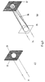
- Fig. 2 shows speckles in the far field of the projection screen 21, corresponding to the Situation with laser large-screen projection, with an observation distance of 5 m and an image spot diameter 22 of 10 mm.
- the speckles at the place of Observers 23 are already relatively large at approximately 0.5 mm.
- a relative phase shift brings the top to the bottom of the lighting beam only an imperceptible shift of the speckle in the observer, a reduction the speckle contrast is not possible.
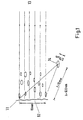
- Fig. 3 shows the beam geometry for the reduction of spatial coherence the light distribution scattered from the screen.
- the untreated projection beam 31 a picture element (pixel) 32 on the screen 33. Speckles occur as in Fig. 2.
- Fig. 3b the laser beam 34 divided into N partial beams 36 by means of a phase hologram 35, which are only partially or not at all superimposed on the screen 37.
- Each beam creates its own speckle pattern, that of the respective one Surface of the screen is dependent.
- a movement of the small spots leads to a movement of the individual speckle patterns.
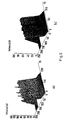
- FIG. 4 shows an example of an intensity distribution of a picture element (pixel) at the observer.
- An unmodified laser beam is used in FIG. 4a). Speckles show a high modulation of the intensity distribution.
- Fif. 4b the pixel is illuminated with 64 partial beams. The through the speckle Incoming intensity modulation is strongly suppressed.
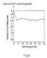
- FIG. 5 shows the measured contrast over the image spot in percent as a function the speed of the phase hologram
- FIG. 6 the measured contrast within a scanned image line at the location of the observer, namely in Fig. 6a) without phase hologram and in Fig. 6b) with stationary hologram.
- phase holograms are included several phase levels or even blazing structures necessary. It has shown in experiments that e.g. 4-16 phase levels are sufficient.
- the structures can be used with laser beam recorders, electron beam recorders etc., but also drawn differently using suitable reduction processes Structures are made. This occurs at typical beam diameters from 5-10 mm the same diameter of the phase plates to (5-10 mm).
- the Structure sizes in the hologram are typically in the ⁇ m range and larger.
- the Manufacturing can be done in photoresist technology, with multiple Layers, chemical etching or ion beam etching in glass or other materials or by means of other existing recording methods become. Above all, a high diffraction efficiency is important from the manufactured item.
- the original laser beam was divided into 4, 8, 16, 32, 64, 128 partial beams. It was found experimentally that 16 partial beams are sufficient and good results bring. With 32, 64 and 128 partial beams, the result is in terms of speckle reduction similar.
- the production of the hologram can also be done on photographic or other known ways inscribed in a thin or thick hologram layer become.
- phase hologram in the sense of the invention multi-color projection e.g. with the red, green and red (RGB) color, either as a single hologram after combining all colors in the Beam path or as separate phase holograms for special optimization can be installed in the individual color channels
- phase hologram in the sense of the invention can not only Projection onto screens, but also to reduce speckles when projecting from behind of light-transmitting screens or with a scanned illumination used by holograms.
Landscapes
- Physics & Mathematics (AREA)
- General Physics & Mathematics (AREA)
- Optics & Photonics (AREA)
- Projection Apparatus (AREA)
- Holo Graphy (AREA)
- Diffracting Gratings Or Hologram Optical Elements (AREA)
- Mechanical Optical Scanning Systems (AREA)
Description
- Fig. 1:
- eine schematische Darstellung der Entstehung der Speckles im Raum vor einem Bildschirm im Nahfeld,
- Fig. 2:
- eine schematische Darstellung der Enstehung der Speckles im Raum vor einem Bildschirm im Fernfeld,
- Fig. 3:
- eine schematische Darstellung der Strahlgeometrie bei der Laserprojektion
- a) ohne Aufteilung des Beleuchtungsstrahles,
- b) nach Aufteilung des Beleuchtungsstrahles in eine Anzahl von Teilstrahlen durch das Phasenhologramm und
- Fig. 4:
- eine Kamera-Aufzeichnung der gesehenen Intensitätsverteilung im
Femfeld des Bildflecks
- a) ohne Phasenhologram und
- b) mit Phasenhologramm.
Claims (14)
- Verfahren zur Beseitigung von Bildspeckles bei scannender Laserbildprojektion, bei dem mittels eines Phasenhologramms (35) oder einer strahlformenden Einrichtung der Beleuchtungsstrahl (34) eines Projektors in Teilstrahlen (36) aufgeteilt wird, dadurch gekennzeichnet, daß
jeder der erzeugten Teilstrahlen (36) eine kleinere Fläche ausleuchtet als der Beleuchtungsstrahl (34),
wobei die Teilstrahlen (36) auf einem Bildschirm (37) innerhalb eines zu projizierenden Bildelements (32) bewegt und wieder so überlagert werden, daß unterschiedliche Specklepatterns entstehen, die sich im Auge des Beobachters zeitlich und/oder örtlich ausmitteln. - Verfahren nach Anspruch 1, dadurch gekennzeichnet, dass als strahlformende Einrichtung ein Linsenarray oder eine Fresnelzonenplatte verwendet wird.
- Vorrichtung zur Beseitigung von Bildspeckles bei scannender Laserbildprojektion, mit einem Projektor zur Erzeugung eines Beleuchtungsstrahls (34), und
einer Einrichtung zum Aufteilen des Beleuchtungsstrahls (34) in Teilstrahlen (36), dadurch gekennzeichnet, daß
die Einrichtung zum Aufteilen des Beleuchtungsstrahls ein Phasenhologramm (35) oder eine strahlformende Einrichtung ist, wobei
jeder der erzeugten Teilstrahlen (36) eine kleinere Fläche ausleuchtet als der Beleuchtungsstrahl (34), und
Mittel vorgesehen sind, die die Teilstrahlen (36) auf einem Bildschirm (37) innerhalb eines zu projizierenden Bildelements (32) bewegen und wieder so überlagern, daß unterschiedliche Specklepatterns entstehen, die sich im Auge des Beobachters zeitlich und/oder örtlich ausmitteln. - Vorrichtung nach Anspruch 3, dadurch gekennzeichnet, daß die strahlformende Einrichtung drehbar oder seitwärts periodisch auslenkbar ist, so daß die Teilstrahlen (36) auf dem Bildschirm (37) bewegbar sind.
- Vorrichtung nach Anspruch 3, dadurch gekennzeichnet, daß die Struktur des Phasenhologramms (35) beispielsweise mit einer extern ansteuerbaren Flüssigkristallzelle zeitlich veränderbar ist, und damit eine Bewegung der Teilstrahlen (36) auf dem Bildschirm (37) erfolgt.
- Vorrichtung nach Anspruch 3, dadurch gekennzeichnet, daß ein optischer Bildrotator oder ein anderes vergleichbares Element hinter dem Phasenhologramm (35) angeordnet ist, das eine Drehbewegung der Teilstrahlen (36) ausübt.
- Vorrichtung nach dem Verfahren gemäß Anspruch 3 oder 4, dadurch gekennzeichnet, daß sich das Phasenhologramm (35) hinter, vor oder innerhalb einer Scannnereinrichtung befindet
- Vorrichtung nach Anspruch 3, dadurch gekennzeichnet, daß das Phasenhologramm (35) in einer Zwischenbildebene eines Projektionsobjektives eines Bildprojektors liegt.
- Vorrichtung nach Anspruch 3, dadurch gekennzeichnet, daß das Phasenhologramm (35) stillsteht und die Teilstrahlen (36) mittels eines Bildscanners oder anderen entsprechenden Einrichtungen über den Bildschirm (37) bewegbar sind.
- Vorrichtung nach Anspruch 3, dadurch gekennzeichnet, daß zur Bewegung eine Einrichtung zur Translation oder Rotation des Phasenhologramms (35) vorgesehen ist.
- Vorrichtung nach Anspruch 3, dadurch gekennzeichnet, daß bei Farbprojektion ein einziges Phasenhologramm (35) gleichzeitig für die drei Grundfarben vorgesehen ist.
- Vorrichtung nach Anspruch 3 dadurch gekennzeichnet, daß bei Farbprojektion für jede Farbe ein separates Phasenhologramm (35) vorgesehen ist.
- Vorrichtung nach Anspruch 3, dadurch gekennzeichnet, daß zusätzlich zum Phasenhologramm (35) weitere optische Elemente zur Mitformung des Strahlprofils zusätzlich vorgesehen sind.
- Vorrichtung nach Anspruch 3, dadurch gekennzeichnet, daß zur Bildwiedergabe ein Aufprojektionsschirm, ein Rückprojektionsschirm oder ein Hologramm vorgesehen ist.
Applications Claiming Priority (3)
| Application Number | Priority Date | Filing Date | Title |
|---|---|---|---|
| DE19703730A DE19703730A1 (de) | 1997-01-31 | 1997-01-31 | Verfahren und Vorrichtung zur Beseitigung von Bildspeckles bei scannender Laserbildprojektion |
| DE19703730 | 1997-01-31 | ||
| PCT/EP1998/000134 WO1998034409A1 (de) | 1997-01-31 | 1998-01-13 | Verfahren und vorrichtung zur beseitigung von bildspeckles bei scannender laserbildprojektion |
Publications (2)
| Publication Number | Publication Date |
|---|---|
| EP0956706A1 EP0956706A1 (de) | 1999-11-17 |
| EP0956706B1 true EP0956706B1 (de) | 2002-07-03 |
Family
ID=7818986
Family Applications (1)
| Application Number | Title | Priority Date | Filing Date |
|---|---|---|---|
| EP98901961A Expired - Lifetime EP0956706B1 (de) | 1997-01-31 | 1998-01-13 | Verfahren und vorrichtung zur beseitigung von bildspeckles bei scannender laserbildprojektion |
Country Status (5)
| Country | Link |
|---|---|
| US (1) | US6367935B1 (de) |
| EP (1) | EP0956706B1 (de) |
| JP (1) | JP2001509911A (de) |
| DE (2) | DE19703730A1 (de) |
| WO (1) | WO1998034409A1 (de) |
Families Citing this family (18)
| Publication number | Priority date | Publication date | Assignee | Title |
|---|---|---|---|---|
| US6629641B2 (en) * | 2000-06-07 | 2003-10-07 | Metrologic Instruments, Inc. | Method of and system for producing images of objects using planar laser illumination beams and image detection arrays |
| US7832643B2 (en) * | 1998-03-24 | 2010-11-16 | Metrologic Instruments, Inc. | Hand-supported planar laser illumination and imaging (PLIIM) based systems with laser despeckling mechanisms integrated therein |
| US8042740B2 (en) | 2000-11-24 | 2011-10-25 | Metrologic Instruments, Inc. | Method of reading bar code symbols on objects at a point-of-sale station by passing said objects through a complex of stationary coplanar illumination and imaging planes projected into a 3D imaging volume |
| US7156522B2 (en) * | 2003-07-16 | 2007-01-02 | Plut William J | Projection-type display devices with reduced weight and size |
| US7281807B2 (en) | 2003-07-16 | 2007-10-16 | Honeywood Technologies, Llc | Positionable projection display devices |
| US7586959B2 (en) * | 2004-09-27 | 2009-09-08 | Applied Materials, Israel, Ltd. | Speckle reduction with transparent blocks |
| US7889422B2 (en) * | 2005-06-02 | 2011-02-15 | Panasonic Corporation | Two-dimensional image display device |
| EP2082280A2 (de) * | 2006-11-07 | 2009-07-29 | Koninklijke Philips Electronics N.V. | Verfahren und vorrichtung zur speckle-reduktion |
| DE112007003437B4 (de) * | 2007-01-24 | 2019-11-28 | Osram Gmbh | Optoelektronische Vorrichtung |
| JP4999583B2 (ja) | 2007-07-18 | 2012-08-15 | キヤノン株式会社 | 光走査装置及び走査型画像表示装置 |
| US20090040527A1 (en) * | 2007-07-20 | 2009-02-12 | Paul Dan Popescu | Method and apparatus for speckle noise reduction in electromagnetic interference detection |
| DE102007045332B4 (de) * | 2007-09-17 | 2019-01-17 | Seereal Technologies S.A. | Holographisches Display zum Rekonstruieren einer Szene |
| US7843558B2 (en) | 2008-06-25 | 2010-11-30 | Applied Materials South East Asia Pte. Ltd. | Optical inspection tools featuring light shaping diffusers |
| US7944598B2 (en) * | 2008-11-06 | 2011-05-17 | Corning Incorporated | Speckle mitigation in laser scanner projector systems |
| US8077367B2 (en) * | 2009-04-29 | 2011-12-13 | Corning Incorporated | Speckle mitigation in laser projection systems |
| US8130433B2 (en) * | 2009-04-29 | 2012-03-06 | Corning Incorporated | Spinning optics for speckle mitigation in laser projection systems |
| US8848200B2 (en) | 2011-10-05 | 2014-09-30 | Daniel Feldkhun | Systems and methods for suppressing coherent structured illumination artifacts |
| US9709953B2 (en) | 2012-08-01 | 2017-07-18 | Real View Imaging Ltd. | Despeckling a computer generated hologram |
Family Cites Families (10)
| Publication number | Priority date | Publication date | Assignee | Title |
|---|---|---|---|---|
| US4913547A (en) * | 1988-01-29 | 1990-04-03 | Moran Steven E | Optically phased-locked speckle pattern interferometer |
| JP2914037B2 (ja) * | 1991-09-30 | 1999-06-28 | キヤノン株式会社 | スペックル干渉装置 |
| US5313479A (en) | 1992-07-29 | 1994-05-17 | Texas Instruments Incorporated | Speckle-free display system using coherent light |
| US5534950A (en) | 1993-10-04 | 1996-07-09 | Laser Power Corporation | High resolution image projection system and method employing lasers |
| US5434662A (en) * | 1993-12-23 | 1995-07-18 | Hughes Aircraft Company | Speckle resistant method and apparatus with chirped laser beam |
| DE19508754C2 (de) | 1995-03-10 | 1999-06-02 | Ldt Gmbh & Co | Verfahren und Vorrichtung zum Vermindern von Interferenzen eines kohärenten Lichtbündels |
| IL124906A (en) * | 1996-11-07 | 2000-12-06 | Ldt Gmbh & Co | Device with a laser for image presentation |
| US6154259A (en) * | 1996-11-27 | 2000-11-28 | Photera Technologies, Inc. | Multi-beam laser scanning display system with speckle elimination |
| US6183092B1 (en) * | 1998-05-01 | 2001-02-06 | Diane Troyer | Laser projection apparatus with liquid-crystal light valves and scanning reading beam |
| US6184981B1 (en) * | 1998-07-28 | 2001-02-06 | Textron Systems Corporation | Speckle mitigation for coherent detection employing a wide band signal |
-
1997
- 1997-01-31 DE DE19703730A patent/DE19703730A1/de not_active Ceased
-
1998
- 1998-01-13 JP JP53248198A patent/JP2001509911A/ja active Pending
- 1998-01-13 EP EP98901961A patent/EP0956706B1/de not_active Expired - Lifetime
- 1998-01-13 US US09/355,288 patent/US6367935B1/en not_active Expired - Fee Related
- 1998-01-13 WO PCT/EP1998/000134 patent/WO1998034409A1/de not_active Ceased
- 1998-01-13 DE DE59804663T patent/DE59804663D1/de not_active Expired - Lifetime
Also Published As
| Publication number | Publication date |
|---|---|
| US6367935B1 (en) | 2002-04-09 |
| DE59804663D1 (de) | 2002-08-08 |
| JP2001509911A (ja) | 2001-07-24 |
| DE19703730A1 (de) | 1998-08-06 |
| WO1998034409A1 (de) | 1998-08-06 |
| EP0956706A1 (de) | 1999-11-17 |
Similar Documents
| Publication | Publication Date | Title |
|---|---|---|
| DE69805645T2 (de) | Anzeigegerät mit einem gitter-lichtventilarray und interferometrisches optisches system | |
| EP0956706A1 (de) | Verfahren und vorrichtung zur beseitigung von bildspeckles bei scannender laserbildprojektion | |
| DE69122677T2 (de) | Farbflüssigkristallanzeigevorrichtung | |
| DE69603374T2 (de) | Autostereoskopische anzeige | |
| DE19924096C2 (de) | System zur stereoskopischen Bilddarstellung | |
| DE19508754C2 (de) | Verfahren und Vorrichtung zum Vermindern von Interferenzen eines kohärenten Lichtbündels | |
| DE69523300T2 (de) | Bauelement zur strahlzusammenführung und eine dieses enthaltende farbbildprojektionsvorrichtung | |
| DE102012215540B4 (de) | Individualisierungseinrichtung und Belichtungsvorrichtung für Hologramme | |
| EP0907902B1 (de) | Verfahren zur dreidimensionalen bilddarstellung auf einer grossbildprojektionsfläche mittels eines laser-projektors | |
| DE102011056552A1 (de) | Verfahren und Vorrichtung zur Herstellung eines holographischen Bildschirmes für elektronische Aufprojektion | |
| DE19627568A1 (de) | Anordnung und Verfahren zur konfokalen Mikroskopie | |
| DE19831239A1 (de) | Vorrichtung zur Trennung eines Lichtstrahls durch Verwendung zweier flacher Platten mit einem dazwischenliegenden Luftspalt und dichroitischen Hybridspiegeln und ein Verfahren dafür | |
| DE69623311T2 (de) | Optisch variables element, methode zu seiner aufnahme und aufnahmevorrichtung dazu | |
| DE69015170T2 (de) | Anzeigemittel. | |
| EP1084432B1 (de) | Projektionsschirm | |
| WO2007062644A1 (de) | Multiperspektiven-rückprojektionssystem zur autostereoskopen wiedergabe von dreidimensionalen darstellungen | |
| DE19710660C2 (de) | Vorrichtung zur Beseitigung oder Reduktion von Bildspeckles | |
| WO2025237589A1 (de) | Anzeigevorrichtung und verfahren zum betreiben einer anzeigevorrichtung | |
| WO2017055149A1 (de) | Vorrichtung zur datenprojektion | |
| DE102008008232B4 (de) | Vorrichtung und Verfahren zum Belichten eines Fotomaterials | |
| DE2435904A1 (de) | Vorrichtung zur erzeugung eines mehrfarbigen strahls sowie verfahren zum erzeugen eines solchen strahls | |
| DE102005037435B4 (de) | Vorrichtung zur umschaltbaren Bildprojektion mit diffraktiven optischen Elementen und Verfahren zur umschaltbaren Bildprojektion | |
| DE69817028T2 (de) | Projektionsfernsehgeräte mit holographischen bildschirmen und aufeinandergestapelten elementen | |
| EP3807709B1 (de) | Optisches element für ein head-up-display | |
| EP0177852A2 (de) | Verfahren zur Herstellung eines mit Weisslicht rekonstruierbaren prägefähigen Schwarz-Weiss-Hologramms |
Legal Events
| Date | Code | Title | Description |
|---|---|---|---|
| PUAI | Public reference made under article 153(3) epc to a published international application that has entered the european phase |
Free format text: ORIGINAL CODE: 0009012 |
|
| 17P | Request for examination filed |
Effective date: 19990813 |
|
| AK | Designated contracting states |
Kind code of ref document: A1 Designated state(s): DE FR GB IT SE |
|
| 17Q | First examination report despatched |
Effective date: 20000927 |
|
| RAP1 | Party data changed (applicant data changed or rights of an application transferred) |
Owner name: EADS DEUTSCHLAND GMBH |
|
| GRAG | Despatch of communication of intention to grant |
Free format text: ORIGINAL CODE: EPIDOS AGRA |
|
| GRAG | Despatch of communication of intention to grant |
Free format text: ORIGINAL CODE: EPIDOS AGRA |
|
| GRAH | Despatch of communication of intention to grant a patent |
Free format text: ORIGINAL CODE: EPIDOS IGRA |
|
| GRAH | Despatch of communication of intention to grant a patent |
Free format text: ORIGINAL CODE: EPIDOS IGRA |
|
| GRAA | (expected) grant |
Free format text: ORIGINAL CODE: 0009210 |
|
| AK | Designated contracting states |
Kind code of ref document: B1 Designated state(s): DE FR GB IT SE |
|
| REF | Corresponds to: |
Ref document number: 59804663 Country of ref document: DE Date of ref document: 20020808 |
|
| GBT | Gb: translation of ep patent filed (gb section 77(6)(a)/1977) |
Effective date: 20020721 |
|
| ET | Fr: translation filed | ||
| PLBE | No opposition filed within time limit |
Free format text: ORIGINAL CODE: 0009261 |
|
| STAA | Information on the status of an ep patent application or granted ep patent |
Free format text: STATUS: NO OPPOSITION FILED WITHIN TIME LIMIT |
|
| 26N | No opposition filed |
Effective date: 20030404 |
|
| PGFP | Annual fee paid to national office [announced via postgrant information from national office to epo] |
Ref country code: IT Payment date: 20110125 Year of fee payment: 14 Ref country code: FR Payment date: 20110202 Year of fee payment: 14 Ref country code: SE Payment date: 20110113 Year of fee payment: 14 Ref country code: DE Payment date: 20110121 Year of fee payment: 14 |
|
| PGFP | Annual fee paid to national office [announced via postgrant information from national office to epo] |
Ref country code: GB Payment date: 20110120 Year of fee payment: 14 |
|
| REG | Reference to a national code |
Ref country code: SE Ref legal event code: EUG |
|
| GBPC | Gb: european patent ceased through non-payment of renewal fee |
Effective date: 20120113 |
|
| REG | Reference to a national code |
Ref country code: FR Ref legal event code: ST Effective date: 20120928 |
|
| PG25 | Lapsed in a contracting state [announced via postgrant information from national office to epo] |
Ref country code: GB Free format text: LAPSE BECAUSE OF NON-PAYMENT OF DUE FEES Effective date: 20120113 Ref country code: SE Free format text: LAPSE BECAUSE OF NON-PAYMENT OF DUE FEES Effective date: 20120114 Ref country code: DE Free format text: LAPSE BECAUSE OF NON-PAYMENT OF DUE FEES Effective date: 20120801 |
|
| REG | Reference to a national code |
Ref country code: DE Ref legal event code: R119 Ref document number: 59804663 Country of ref document: DE Effective date: 20120801 |
|
| PG25 | Lapsed in a contracting state [announced via postgrant information from national office to epo] |
Ref country code: IT Free format text: LAPSE BECAUSE OF NON-PAYMENT OF DUE FEES Effective date: 20120113 |
|
| PG25 | Lapsed in a contracting state [announced via postgrant information from national office to epo] |
Ref country code: FR Free format text: LAPSE BECAUSE OF NON-PAYMENT OF DUE FEES Effective date: 20120131 |