EP0955456B1 - Gasturbinenanlage mit einer Zustromleitung - Google Patents
Gasturbinenanlage mit einer Zustromleitung Download PDFInfo
- Publication number
- EP0955456B1 EP0955456B1 EP19990108167 EP99108167A EP0955456B1 EP 0955456 B1 EP0955456 B1 EP 0955456B1 EP 19990108167 EP19990108167 EP 19990108167 EP 99108167 A EP99108167 A EP 99108167A EP 0955456 B1 EP0955456 B1 EP 0955456B1
- Authority
- EP
- European Patent Office
- Prior art keywords
- gas turbine
- region
- housing
- flow
- flow body
- Prior art date
- Legal status (The legal status is an assumption and is not a legal conclusion. Google has not performed a legal analysis and makes no representation as to the accuracy of the status listed.)
- Expired - Lifetime
Links
- 239000002184 metal Substances 0.000 claims 3
- 239000003570 air Substances 0.000 description 30
- 239000000446 fuel Substances 0.000 description 4
- 238000000926 separation method Methods 0.000 description 4
- 238000002485 combustion reaction Methods 0.000 description 3
- 238000012423 maintenance Methods 0.000 description 3
- 230000006378 damage Effects 0.000 description 2
- 230000004941 influx Effects 0.000 description 2
- 230000001154 acute effect Effects 0.000 description 1
- 239000012080 ambient air Substances 0.000 description 1
- 238000009434 installation Methods 0.000 description 1
- 239000000203 mixture Substances 0.000 description 1
- 230000007704 transition Effects 0.000 description 1
- 238000011144 upstream manufacturing Methods 0.000 description 1
Images
Classifications
-
- F—MECHANICAL ENGINEERING; LIGHTING; HEATING; WEAPONS; BLASTING
- F02—COMBUSTION ENGINES; HOT-GAS OR COMBUSTION-PRODUCT ENGINE PLANTS
- F02C—GAS-TURBINE PLANTS; AIR INTAKES FOR JET-PROPULSION PLANTS; CONTROLLING FUEL SUPPLY IN AIR-BREATHING JET-PROPULSION PLANTS
- F02C7/00—Features, components parts, details or accessories, not provided for in, or of interest apart form groups F02C1/00 - F02C6/00; Air intakes for jet-propulsion plants
- F02C7/04—Air intakes for gas-turbine plants or jet-propulsion plants
Definitions
- the invention relates to a gas turbine plant.
- a gas turbine plant is usually used for generating electrical energy.
- the energy content of a fuel is used to generate a rotational movement of a turbine shaft, which in turn drives a generator or a working machine.
- ambient air is usually sucked in and compressed in a compressor associated with the gas turbine to a high pressure. Most of the compressed air enters one or more combustion chambers where it is used to burn the fuel. The mixture ignited there is then fed to the gas turbine.
- Such a gas turbine plant usually has an air intake duct, which is provided for supplying air into the housing of the air compressor.
- a deflection of the flow of air can be provided. When deflecting the flow, this can detach from the wall and form turbulence. This can cause pressure losses in the gaseous medium, which in turn can lead to undesirable power losses of the gas turbine.
- a deflection of the flow by approximately 90 ° is often provided at the point at which the air intake duct opens into the housing of the air compressor.
- a designated as Bell Mouth component is arranged, which covers the entire inner circumference encloses the air intake duct. This component rounds corners and / or edges in the junction area so that the risk of flow separation from the wall in the junction area is kept particularly low. Due to the size of the inner circumference of the air intake duct of, for example, 5m, the design and installation of the bell mouth at the outlet of the air intake duct are particularly complicated. The required disassembly of the bell mouth during maintenance and repair of the air intake duct and / or the housing of the air compressor also requires a particularly high work and time and thus limits the availability of the gas turbine plant in an undesirable manner.
- the invention is therefore based on the object of specifying a gas turbine plant of the type mentioned above, in which a concern of the flow of the gaseous medium to a guide wall in the junction region of an influx line is ensured in a housing and maintenance and repair work with very little technical effort are feasible.
- This object is achieved according to the invention for a gas turbine plant of the above type by an arranged in the junction area in the housing flow body, which causes the housing to be supplied flow of the gaseous medium in the entire junction area abuts a guide wall, an inner periphery of the junction area of the feed line only to a predetermined proportion of less than two-thirds.
- the invention is based on the consideration that a concern of the flow in the junction region of the feed line is ensured in the housing when a flow body is arranged in the junction region, which rounds off edges of the junction area in a suitable manner. Edges of the confluence area prove to be particularly critical with respect to a separation of the flow from the wall when at the entrance of the flow in the housing, a deflection of the flow is provided by about 90 °. However, the flow body should only round off the edges where there is a risk of flow separation. This is given in the edge connecting the guide wall with the housing, in which a deflection of the flow takes place by about 90 °.
- a particularly easy to assemble flow body is one that includes only a part of the inner circumference of the influx line. For this purpose, the flow body comprises the inner circumference of the confluence region of the inflow line to a predetermined proportion, advantageously half.
- the housing into which the feed line opens that of the air compressor of the gas turbine plant.
- the air compressor of the gas turbine plant namely designed as an air intake duct feed line
- the housing into which the feed line opens can be arranged with a particularly small footprint next to the housing of the air compressor, at the same time ensuring that the flow of the gaseous medium does not tear off the guide wall. In this case, even an acute angle between the feed line and the housing is possible.
- the flow body advantageously tapers along the inner circumference of the confluence area of the inflow conduit to its two ends. In this way, a particularly smooth transition between the provided with the flow body portion of the inner circumference of the confluence region and the not provided with flow body portion of the inner periphery of the junction region is ensured, so that a particularly reliable demolition of the flow is prevented.
- the flow body is composed of a number of sheets.
- the plates expediently have a smaller angle of inclination relative to the guide wall in the inflow region than the plates in the outflow region.
- the flow body is in each case at the individual angle between the inflow line and the housing adaptable and thus ensures particularly reliable that the flow does not tear off the wall.
- the advantages achieved by the invention are in particular that in the gas turbine plant, the risk of flow separation from the guide wall of an inflow line in the junction area is avoided in a housing with very little technical effort.
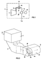
- gas turbine plant 2 comprises a gas turbine 4 with coupled air compressor 6.
- the air compressor 6 is connected on the input side to a provided for air as gaseous medium M supply line 8.
- the gas turbine 4 is connected upstream via a supply line 10, a combustion chamber 12 which is connected to the output or fresh air line 14 of the air compressor 6.
- a combustion chamber 12 of the gas turbine 4 opens a provided for fuel B fuel line 16.
- the gas turbine. 4 and the air compressor 6 and a generator 18 are seated on a common turbine shaft 20.
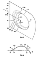
- FIG. 2 schematically the connection between the feed line 8 and the housing 22 of the air compressor 6 is shown.
- a gaseous medium M air passes through an output housing 7 and the feed line 8 into the housing 22 of the air compressor 6.
- a composed of sheets 27 flow body 26 as a part Bell Mouth arranged. This encloses the inner circumference 28 of the confluence region 24 on the guide wall 30 approximately halfway.
- a deflection of the gaseous medium M by 90 ° in the direction of the air compressor 6 instead.
- FIG. 3 shows in detail that the flow body 26 rounds off the connecting edge between the guide wall 30 of the feed line 8 and the housing 22 of the air compressor 6.
- the flow body 26 tapers along the inner periphery 28 of the confluence region 24 towards its two ends 26a and 26b.
- FIG. 4 A section according to IV - IV in FIG. 3 of the flow body 26 shows FIG. 4 , According to FIG. 4 the sheets 27 of the flow body 26 in the inflow 32 a different angle of inclination 34 relative to the guide wall 30 as in the outflow 36th
- the flow body 26 can be manufactured with a particularly low technical outlay and can be attached particularly easily to the guide wall 30 in the junction region 24 of the inflow line 8.
- the gas turbine plant 2 a particularly low maintenance and repair costs.
- a concern of the flow of air to the guide wall 30 of the feed line 8 in the junction region 24 is ensured particularly reliable.
Landscapes
- Engineering & Computer Science (AREA)
- Chemical & Material Sciences (AREA)
- Combustion & Propulsion (AREA)
- Mechanical Engineering (AREA)
- General Engineering & Computer Science (AREA)
- Structures Of Non-Positive Displacement Pumps (AREA)
- Turbine Rotor Nozzle Sealing (AREA)
Description
- Die Erfindung bezieht sich auf eine Gasturbinenanlage.
- Eine Gasturbinenanlage wird üblicherweise zur Erzeugung elektrischer Energie eingesetzt. Dabei wird der Energieinhalt eines Brennstoffes zur Erzeugung einer Rotationsbewegung einer Turbinenwelle genutzt, die wiederum einen Generator oder eine Arbeitsmaschine antreibt. Beim Betrieb der Gasturbinenanlage wird üblicherweise Umgebungsluft angesaugt und in einem der Gasturbine zugeordneten Verdichter auf einen hohen Druck verdichtet. Der größte Anteil der verdichteten Luft gelangt in eine oder mehrere Brennkammern und wird dort zur Verbrennung des Brennstoffs eingesetzt. Das dort entzündete Gemisch wird sodann der Gasturbine zugeführt.
- Eine derartige Gasturbinenanlage weist üblicherweise einen Luftansaugkanal auf, der zur Zuführung von Luft in das Gehäuse des Luftverdichters vorgesehen ist. Dabei kann eine Umlenkung der Strömung der Luft vorgesehen sein. Bei der Umlenkung der Strömung kann diese sich von der Wand ablösen und Verwirbelungen bilden. Hierdurch können Druckverluste im gasförmigen Medium entstehen, die wiederum zu unerwünschten Leistungsverlusten der Gasturbine führen können. Außerdem besteht die Gefahr, daß mit der Strömung in Kontakt stehende Bauteile durch Wirbel der Strömung in Schwingungen versetzt werden, was zu Schäden und im Extremfall zu einer Zerstörung der gesamten Anlage führen kann.
- Eine Umlenkung der Strömung um annähernd 90° ist häufig an der Stelle vorgesehen, an der der Luftansaugkanal in das Gehäuse des Luftverdichters mündet. Üblicherweise ist deswegen im auch als Auslauf bezeichneten Einmündungsbereich des Luftansaugkanals in das Gehäuse des Luftverdichters ein als Bell-Mouth bezeichnetes Bauteil angeordnet, das den gesamten Innenumfang des Luftansaugkanals umschließt. Dieses Bauteil rundet Ecken und/oder Kanten im Einmündungsbereich so ab, daß die Gefahr einer Strömungsablösung von der Wand im Einmündungsbereich besonders gering gehalten ist. Aufgrund der Größe des Innenumfangs des Luftansaugkanals von beispielsweise 5m gestalten sich hierbei die Konstruktion und die Montage der Bell-Mouth am Auslauf des Luftansaugkanals besonders aufwendig. Die erforderliche Demontage der Bell-Mouth bei Wartungs- und Reparaturarbeiten des Luftansaugkanals und/oder dem Gehäuse des Luftverdichters bedingt außerdem einen besonders hohen Arbeits- und Zeitaufwand und schränkt somit die Verfügbarkeit der Gasturbinenanlage in unerwünschter Weise ein.
- Dokument
DE 4326800 offenbart eine gattungsgemäße Gasturbinenanlage. - Der Erfindung liegt daher die Aufgabe zugrunde, eine Gasturbinenanlage der oben genannten Art anzugeben, bei der ein Anliegen der Strömung des gasförmigen Mediums an einer Führungswand im Einmündungsbereich einer Zustromleitung in ein Gehäuse gewährleistet ist und Wartungs- und Reparaturarbeiten mit besonders geringem technischen Aufwand durchführbar sind.
- Diese Aufgabe wird für eine Gasturbinenanlage der oben genannten Art erfindungsgemäß gelöst, indem ein im Einmündungsbereich in das Gehäuse angeordneter Strömungskörper, der bewirkt, daß die dem Gehäuse zuzuführende Strömung des gasförmigen Mediums im gesamten Einmündungsbereich an einer Führungswand anliegt, einen Innenumfang des Einmündungsbereichs der Zustromleitung lediglich zu einem vorgegebenen Anteil von weniger als zwei Drittel umschließt.
- Die Erfindung geht dabei von der Überlegung aus, daß ein Anliegen der Strömung im Einmündungsbereich der Zustromleitung in das Gehäuse dann gewährleistet ist, wenn im Einmündungsbereich ein Strömungskörper angeordnet ist, der in geeigneter Weise Kanten des Einmündungsbereiches abrundet. Kanten des Einmündungsbereichs erweisen sich als besonders kritisch im Hinblick auf eine Ablösung der Strömung von der Wand, wenn beim Eintritt der Strömung in das Gehäuse eine Umlenkung der Strömung um etwa 90° vorgesehen ist. Dabei sollte der Strömungskörper jedoch nur die Kanten abrunden, bei denen die Gefahr einer Strömungsablösung besteht. Dies ist bei der die Führungswand mit dem Gehäuse verbindenden Kante gegeben, bei der eine Umlenkung der Strömung um etwa 90° erfolgt. Ein besonders montagefreundlicher Strömungskörper ist einer, der nur einen Teil-Innenumfang der Zustromleitung umfaßt. Hierzu umfaßt der Strömungskörper den Innenumfang des Einmündungsbereichs der Zustromleitung zu einem vorgegebenen Anteil, vorteilhafterweise zur Hälfte.
- Vorteilhafterweise ist das Gehäuse, in das die Zustromleitung mündet, das des Luftverdichters der Gasturbinenanlage. In dieser Ausgestaltung kann nämlich die als Luftansaugkanal ausgebildete Zustromleitung mit besonders geringem Platzbedarf neben dem Gehäuse des Luftverdichters angeordnet sein, wobei gleichzeitig gewährleistet ist, daß die Strömung des gasförmigen Mediums nicht von der Führungswand abreißt. Hierbei ist sogar ein spitzer Winkel zwischen der Zustromleitung und dem Gehäuse möglich.
- Der Strömungskörper verjüngt sich vorteilhafterweise entlang des Innenumfangs des Einmündungsbereichs der Zustromleitung zu seinen beiden Enden hin. Auf diese Weise ist ein besonders glatter Übergang zwischen dem mit dem Strömungskörper versehenen Teilbereich des Innenumfangs des Einmündungsbereichs und dem nicht mit Strömungskörper versehenen Teilbereich des Innenumfangs des Einmündungsbereichs gewährleistet, so daß besonders zuverlässig ein Abriß der Strömung verhindert ist.
- Vorteilhafterweise ist der Strömungskörper aus einer Anzahl von Blechen zusammengesetzt. Dabei weisen die Bleche im Anströmbereich zweckmäßigerweise einen kleineren Neigungswinkel relativ zur Führungswand auf als die Bleche im Abströmbereich. In dieser Ausgestaltung ist der Strömungskörper jeweils an den individuellen Winkel zwischen der Zustromleitung und dem Gehäuse anpaßbar und gewährleistet damit besonders zuverlässig, daß die Strömung nicht von der Wand abreißt.
- Die mit der Erfindung erzielten Vorteile bestehen insbesondere darin, daß bei der Gasturbinenanlage die Gefahr einer Strömungsablösung von der Führungswand einer Zustromleitung im Einmündungsbereich in ein Gehäuse mit besonders geringem technischen Aufwand vermieden ist.
- Ein Ausführungsbeispiel der Erfindung wird anhand einer Zeichnung näher erläutert. Darin zeigen:
- FIG 1
- schematisch eine Gasturbinenanlage,
- FIG 2
- einen Strömungskörper, der im Einmündungsbereich einer in ein Gehäuse mündenden Zustromleitung ange- ordnet ist,
- FIG 3
- schematisch den im Einmündungsbereich der Zustrom- leitung angeordneten Strömungskörper gemäß
Figur 2 und - FIG 4
- schematisch einen Schnitt IV - IV des Strömungs- körpers gemäß
Figur 3 . - Die Bezugszeichen in allen Figuren haben dieselbe Bedeutung.
- Die in
Figur 1 schematisch dargestellte Gasturbinenanlage 2 umfaßt eine Gasturbine 4 mit angekoppeltem Luftverdichter 6. Der Luftverdichter 6 ist eingangsseitig an eine für Luft als gasförmiges Medium M vorgesehene Zustromleitung 8 angeschlossen. Der Gasturbine 4 ist über eine Zufuhrleitung 10 eine Brennkammer 12 vorgeschaltet, die an die Ausgangs- oder Frischluftleitung 14 des Luftverdichters 6 angeschlossen ist. In die Brennkammer 12 der Gasturbine 4 mündet eine für Brennstoff B vorgesehene Brennstoffleitung 16. Die Gasturbine 4 und der Luftverdichter 6 sowie ein Generator 18 sitzen auf einer gemeinsamen Turbinenwelle 20. - In
Figur 2 ist schematisch die Verbindung zwischen der Zustromleitung 8 und dem Gehäuse 22 des Luftverdichters 6 dargestellt. Dabei gelangt als gasförmiges Medium M Luft über ein Ausganggehäuse 7 und die Zustromleitung 8 in das Gehäuse 22 des Luftverdichters 6. Um einen Abriß der Luftströmung zu verhindern, ist im Einmündungsbereich 24 der Zustromleitung 8 ein aus Blechen 27 zusammengesetzter Strömungskörper 26 als Teil-Bell-Mouth angeordnet. Dieser umschließt den Innenumfang 28 des Einmündungsbereichs 24 an der Führungswand 30 annähernd zur Hälfte. Hier findet eine Umlenkung des gasförmigen Mediums M um 90° in Richtung auf den Luftverdichter 6 statt. -
Figur 3 zeigt im Detail, daß der Strömungskörper 26 die verbindende Kante zwischen der Führungswand 30 der Zustromleitung 8 und dem Gehäuse 22 des Luftverdichters 6 abrundet. Der Strömungskörper 26 verjüngt sich dabei entlang des Innenumfangs 28 des Einmündungsbereichs 24 zu seinen beiden Enden 26a und 26b hin. - Einen Schnitt gemäß IV - IV in
Figur 3 des Strömungskörpers 26 zeigtFigur 4 . GemäßFigur 4 weisen die Bleche 27 des Strömungskörpers 26 im Anströmbereich 32 einen anderen Neigungswinkel 34 relativ zur Führungswand 30 auf als im Abströmbereich 36. - Der Strömungskörper 26 kann mit besonders geringem technischen Aufwand hergestellt und besonders einfach an der Führungswand 30 im Einmündungsbereich 24 der Zustromleitung 8 angebracht werden. Damit weist die Gasturbinenanlage 2 einen besonders geringen Wartungs- und Reparaturaufwand auf. Gleichzeitig ist ein Anliegen der Strömung der Luft an der Führungswand 30 der Zustromleitung 8 im Einmündungsbereich 24 besonders zuverlässig gewährleistet.
Claims (5)
- Gasturbinenanlage (2), bei der eine für eine Zuführung eines gasförmigen Mediums (M) vorgesehene Zustromleitung (8) in ein Gehäuse (22) mündet, mit einem im Einmündungsbereich (24) der Zustromleitung (8) in das Gehäuse (22) angeordneten Strömungskörper (26), der bewirkt, daß die dem Gehäuse (22) zuführbare Strömung des gasförmigen Mediums (M) im gesamten Einmündungsbereich (24) an einer Führungswand (30) anliegt, dadurch gekennzeichnet, daß der Strömungskörper den Innenumfang (28) des Einmündungsbereichs (24) lediglich zu einem vorgegebenen Anteil von weniger als zwei Drittel des Innenumfangs (28) umschließt.
- Gasturbinenanlage (2) nach Anspruch 1, bei der der Strömungskörper (26) den Innenumfang (28) des Einmündungsbereichs (24) annähernd zur Hälfte umschließt.
- Gasturbinenanlage (2) nach Anspruch 1 oder 2, bei der das Gehäuse (22) das des Luftverdichters (6) ist.
- Gasturbinenanlage (2) nach einem der Ansprüche 1 bis 3, bei der der Strömungskörper (26) sich entlang des Innenumfangs (28) des Einmündungsbereichs (24) zu seinen beiden Enden (26a, 26b) hin verjüngt.
- Gasturbinenanlage (2) nach einem der Ansprüche 1 bis 4, bei der der Strömungskörper (26) aus einer Anzahl von Blechen (27a, 27b) zusammengesetzt ist, wobei die Bleche (27a) im Anströmbereich (32) einen anderen Neigungswinkel (34) relativ zur Führungswand (30) aufweisen als die Bleche (27b) im Abströmbereich (36).
Applications Claiming Priority (2)
| Application Number | Priority Date | Filing Date | Title |
|---|---|---|---|
| DE19819769 | 1998-05-04 | ||
| DE1998119769 DE19819769C2 (de) | 1998-05-04 | 1998-05-04 | Gasturbinenanlage |
Publications (3)
| Publication Number | Publication Date |
|---|---|
| EP0955456A2 EP0955456A2 (de) | 1999-11-10 |
| EP0955456A3 EP0955456A3 (de) | 2001-12-12 |
| EP0955456B1 true EP0955456B1 (de) | 2011-12-28 |
Family
ID=7866573
Family Applications (1)
| Application Number | Title | Priority Date | Filing Date |
|---|---|---|---|
| EP19990108167 Expired - Lifetime EP0955456B1 (de) | 1998-05-04 | 1999-04-26 | Gasturbinenanlage mit einer Zustromleitung |
Country Status (2)
| Country | Link |
|---|---|
| EP (1) | EP0955456B1 (de) |
| DE (1) | DE19819769C2 (de) |
Families Citing this family (2)
| Publication number | Priority date | Publication date | Assignee | Title |
|---|---|---|---|---|
| US6520738B2 (en) | 2001-03-15 | 2003-02-18 | Honeywell International, Inc. | Plenum entry bulk swirl generator |
| US9217369B2 (en) * | 2012-03-15 | 2015-12-22 | Siemens Aktiengesellschaft | Compressor inlet manifold for a gas turbine engine |
Family Cites Families (7)
| Publication number | Priority date | Publication date | Assignee | Title |
|---|---|---|---|---|
| DE192795C (de) * | 1905-11-11 | 1908-01-03 | Rohrkrümmer | |
| GB805003A (en) * | 1954-06-25 | 1958-11-26 | W H Allen Sons & Company Ltd | Improvements in and relating to inlet duct arrangements for gas turbines and compressors |
| US3623511A (en) * | 1970-02-16 | 1971-11-30 | Bvs | Tubular conduits having a bent portion and carrying a fluid |
| JPS5548157Y2 (de) * | 1974-05-31 | 1980-11-11 | ||
| JPS60172713A (ja) * | 1984-02-17 | 1985-09-06 | Hitachi Ltd | 流体通路 |
| EP0493302B1 (de) * | 1990-12-24 | 1995-04-12 | United Technologies Corporation | Mechanismus zur Reduzierung von Druckverlusten in Rohrkrümmern |
| DE4326800A1 (de) * | 1993-08-10 | 1995-02-16 | Abb Management Ag | Vorrichtung zur Einstellung einer stabilen Verdichterzuströmung aus dem Einlaufkasten in Gasturbingenanlagen |
-
1998
- 1998-05-04 DE DE1998119769 patent/DE19819769C2/de not_active Expired - Fee Related
-
1999
- 1999-04-26 EP EP19990108167 patent/EP0955456B1/de not_active Expired - Lifetime
Also Published As
| Publication number | Publication date |
|---|---|
| EP0955456A2 (de) | 1999-11-10 |
| DE19819769A1 (de) | 1999-11-11 |
| DE19819769C2 (de) | 2000-03-02 |
| EP0955456A3 (de) | 2001-12-12 |
Similar Documents
| Publication | Publication Date | Title |
|---|---|---|
| DE60133629T2 (de) | Verfahren zum betrieb einer gasturbine mit verstellbaren leitschaufeln | |
| DE1626137C3 (de) | ||
| EP1084327B1 (de) | Gasturbine sowie verfahren zur kühlung einer turbinenstufe | |
| EP1947293B1 (de) | Leitschaufel für eine Gasturbine | |
| DE60211061T2 (de) | Axialturbine mit einer Stufe in einem Abströmkanal | |
| DE1626137B2 (de) | Zweikreis-strahltriebwerk | |
| CH697810B1 (de) | Gasturbinensystem | |
| EP1726814A2 (de) | Strahltriebwerk | |
| DE102008024022A1 (de) | Gasturbinentriebwerk, insbesondere Flugtriebwerk | |
| CH709266B1 (de) | Turbinenschaufel und Verfahren zum Auswuchten eines Spitzendeckbandes einer Turbinenschaufel und Gasturbine. | |
| EP3568597A1 (de) | Rückführstufe und radialturbofluidenergiemaschine | |
| DE3132134C2 (de) | Verfahren und Vorrichtung zur Verminderung des Strömungsquerschnitts für die Auspuffgase im Leitkranz der Turbine eines Abgasturboladers für einen Verbrennungsmotor | |
| DE69026800T2 (de) | Diffusor | |
| EP0999349A2 (de) | Axialturbine | |
| DE2412242A1 (de) | Gasturbinentriebwerk fuer stroemungsdeflektor im fankanal | |
| EP3698021B1 (de) | Diffusoranordnung einer abgasturbine | |
| EP1262637A1 (de) | Verfahren zum Betrieben eines Gasturbinenkraftwerks sowie Gasturbinenkraftwerk | |
| DE102017105760A1 (de) | Gasturbine, Leitschaufelkranz einer Gasturbine und Verfahren zum Herstellen desselben | |
| WO2001016471A1 (de) | Verfahren und einrichtung zur erhöhung des drucks eines gases | |
| DE102010044819B4 (de) | Axialturbine und ein Verfahren zum Abführen eines Stroms von einer Axialturbine | |
| EP0955456A2 (de) | Lufteinlasskanal für eine Gasturbinenanlage | |
| DE112018001747T5 (de) | Gasturbine | |
| DE1278183B (de) | Druckgasanlasseinrichtung fuer ein Gasturbinenstrahltriebwerk | |
| DE1032033B (de) | Stauluftturbine als Kraftquelle fuer Hilfsapparate bei einem Gasturbinenflugzeug | |
| DE1223626B (de) | Strahlrohr fuer Gasturbinentriebwerke |
Legal Events
| Date | Code | Title | Description |
|---|---|---|---|
| PUAI | Public reference made under article 153(3) epc to a published international application that has entered the european phase |
Free format text: ORIGINAL CODE: 0009012 |
|
| AK | Designated contracting states |
Kind code of ref document: A2 Designated state(s): AT BE CH CY DE DK ES FI FR GB GR IE IT LI LU MC NL PT SE Kind code of ref document: A2 Designated state(s): CH DE FR GB LI SE |
|
| AX | Request for extension of the european patent |
Free format text: AL;LT;LV;MK;RO;SI |
|
| PUAL | Search report despatched |
Free format text: ORIGINAL CODE: 0009013 |
|
| AK | Designated contracting states |
Kind code of ref document: A3 Designated state(s): AT BE CH CY DE DK ES FI FR GB GR IE IT LI LU MC NL PT SE |
|
| AX | Request for extension of the european patent |
Free format text: AL;LT;LV;MK;RO;SI |
|
| RIC1 | Information provided on ipc code assigned before grant |
Free format text: 7F 02C 7/04 A, 7F 15D 1/04 B, 7F 04D 29/42 B |
|
| 17P | Request for examination filed |
Effective date: 20020204 |
|
| AKX | Designation fees paid |
Free format text: CH DE FR GB LI SE |
|
| RTI1 | Title (correction) |
Free format text: GAS TURBINE WITH AN INLET CONDUIT |
|
| GRAP | Despatch of communication of intention to grant a patent |
Free format text: ORIGINAL CODE: EPIDOSNIGR1 |
|
| GRAS | Grant fee paid |
Free format text: ORIGINAL CODE: EPIDOSNIGR3 |
|
| GRAA | (expected) grant |
Free format text: ORIGINAL CODE: 0009210 |
|
| AK | Designated contracting states |
Kind code of ref document: B1 Designated state(s): CH DE FR GB LI SE |
|
| REG | Reference to a national code |
Ref country code: GB Ref legal event code: FG4D Free format text: NOT ENGLISH |
|
| REG | Reference to a national code |
Ref country code: CH Ref legal event code: NV Representative=s name: SIEMENS SCHWEIZ AG Ref country code: CH Ref legal event code: EP |
|
| REG | Reference to a national code |
Ref country code: DE Ref legal event code: R096 Ref document number: 59915318 Country of ref document: DE Effective date: 20120223 |
|
| REG | Reference to a national code |
Ref country code: SE Ref legal event code: TRGR |
|
| PLBE | No opposition filed within time limit |
Free format text: ORIGINAL CODE: 0009261 |
|
| STAA | Information on the status of an ep patent application or granted ep patent |
Free format text: STATUS: NO OPPOSITION FILED WITHIN TIME LIMIT |
|
| 26N | No opposition filed |
Effective date: 20121001 |
|
| REG | Reference to a national code |
Ref country code: DE Ref legal event code: R097 Ref document number: 59915318 Country of ref document: DE Effective date: 20121001 |
|
| PGFP | Annual fee paid to national office [announced via postgrant information from national office to epo] |
Ref country code: GB Payment date: 20130415 Year of fee payment: 15 Ref country code: DE Payment date: 20130620 Year of fee payment: 15 Ref country code: SE Payment date: 20130411 Year of fee payment: 15 |
|
| PGFP | Annual fee paid to national office [announced via postgrant information from national office to epo] |
Ref country code: FR Payment date: 20130430 Year of fee payment: 15 |
|
| PGFP | Annual fee paid to national office [announced via postgrant information from national office to epo] |
Ref country code: CH Payment date: 20130708 Year of fee payment: 15 |
|
| REG | Reference to a national code |
Ref country code: DE Ref legal event code: R119 Ref document number: 59915318 Country of ref document: DE |
|
| REG | Reference to a national code |
Ref country code: CH Ref legal event code: PL |
|
| REG | Reference to a national code |
Ref country code: SE Ref legal event code: EUG |
|
| GBPC | Gb: european patent ceased through non-payment of renewal fee |
Effective date: 20140426 |
|
| REG | Reference to a national code |
Ref country code: FR Ref legal event code: ST Effective date: 20141231 |
|
| REG | Reference to a national code |
Ref country code: DE Ref legal event code: R119 Ref document number: 59915318 Country of ref document: DE Effective date: 20141101 |
|
| PG25 | Lapsed in a contracting state [announced via postgrant information from national office to epo] |
Ref country code: DE Free format text: LAPSE BECAUSE OF NON-PAYMENT OF DUE FEES Effective date: 20141101 Ref country code: GB Free format text: LAPSE BECAUSE OF NON-PAYMENT OF DUE FEES Effective date: 20140426 Ref country code: LI Free format text: LAPSE BECAUSE OF NON-PAYMENT OF DUE FEES Effective date: 20140430 Ref country code: CH Free format text: LAPSE BECAUSE OF NON-PAYMENT OF DUE FEES Effective date: 20140430 Ref country code: SE Free format text: LAPSE BECAUSE OF NON-PAYMENT OF DUE FEES Effective date: 20140427 |
|
| PG25 | Lapsed in a contracting state [announced via postgrant information from national office to epo] |
Ref country code: FR Free format text: LAPSE BECAUSE OF NON-PAYMENT OF DUE FEES Effective date: 20140430 |