EP0955447B1 - Sieb für Kontrolle von Sandproduktion mit kathodischem Korrosionsschutz - Google Patents
Sieb für Kontrolle von Sandproduktion mit kathodischem Korrosionsschutz Download PDFInfo
- Publication number
- EP0955447B1 EP0955447B1 EP99303160A EP99303160A EP0955447B1 EP 0955447 B1 EP0955447 B1 EP 0955447B1 EP 99303160 A EP99303160 A EP 99303160A EP 99303160 A EP99303160 A EP 99303160A EP 0955447 B1 EP0955447 B1 EP 0955447B1
- Authority
- EP
- European Patent Office
- Prior art keywords
- screen
- sand control
- wire
- metal
- control screen
- Prior art date
- Legal status (The legal status is an assumption and is not a legal conclusion. Google has not performed a legal analysis and makes no representation as to the accuracy of the status listed.)
- Expired - Lifetime
Links
- 239000004576 sand Substances 0.000 title claims description 98
- 238000004210 cathodic protection Methods 0.000 title description 3
- 229910052751 metal Inorganic materials 0.000 claims description 55
- 239000002184 metal Substances 0.000 claims description 55
- 238000005336 cracking Methods 0.000 claims description 28
- 229910001220 stainless steel Inorganic materials 0.000 claims description 17
- 230000007613 environmental effect Effects 0.000 claims description 15
- 239000010935 stainless steel Substances 0.000 claims description 15
- 238000000034 method Methods 0.000 claims description 8
- 230000000979 retarding effect Effects 0.000 claims description 3
- 230000008878 coupling Effects 0.000 claims 1
- 238000010168 coupling process Methods 0.000 claims 1
- 238000005859 coupling reaction Methods 0.000 claims 1
- 230000007797 corrosion Effects 0.000 description 25
- 238000005260 corrosion Methods 0.000 description 25
- 239000000463 material Substances 0.000 description 20
- 238000004519 manufacturing process Methods 0.000 description 17
- 239000012530 fluid Substances 0.000 description 15
- 239000002245 particle Substances 0.000 description 14
- 229910045601 alloy Inorganic materials 0.000 description 11
- 239000000956 alloy Substances 0.000 description 11
- 230000015572 biosynthetic process Effects 0.000 description 11
- 238000005755 formation reaction Methods 0.000 description 11
- PXHVJJICTQNCMI-UHFFFAOYSA-N Nickel Chemical compound [Ni] PXHVJJICTQNCMI-UHFFFAOYSA-N 0.000 description 10
- 229910000831 Steel Inorganic materials 0.000 description 9
- 150000002739 metals Chemical class 0.000 description 9
- 239000010959 steel Substances 0.000 description 9
- 229910001293 incoloy Inorganic materials 0.000 description 7
- 150000004820 halides Chemical class 0.000 description 6
- 238000012856 packing Methods 0.000 description 6
- 230000036961 partial effect Effects 0.000 description 6
- 238000009434 installation Methods 0.000 description 5
- 229910052759 nickel Inorganic materials 0.000 description 5
- 239000013535 sea water Substances 0.000 description 5
- 239000007789 gas Substances 0.000 description 4
- 230000001419 dependent effect Effects 0.000 description 3
- OKTJSMMVPCPJKN-UHFFFAOYSA-N Carbon Chemical compound [C] OKTJSMMVPCPJKN-UHFFFAOYSA-N 0.000 description 2
- CURLTUGMZLYLDI-UHFFFAOYSA-N Carbon dioxide Chemical compound O=C=O CURLTUGMZLYLDI-UHFFFAOYSA-N 0.000 description 2
- 238000013461 design Methods 0.000 description 2
- 238000009826 distribution Methods 0.000 description 2
- 238000001914 filtration Methods 0.000 description 2
- 229910052739 hydrogen Inorganic materials 0.000 description 2
- 239000001257 hydrogen Substances 0.000 description 2
- 239000007788 liquid Substances 0.000 description 2
- 238000010297 mechanical methods and process Methods 0.000 description 2
- 239000003921 oil Substances 0.000 description 2
- BASFCYQUMIYNBI-UHFFFAOYSA-N platinum Chemical compound [Pt] BASFCYQUMIYNBI-UHFFFAOYSA-N 0.000 description 2
- 239000011148 porous material Substances 0.000 description 2
- 239000011347 resin Substances 0.000 description 2
- 229920005989 resin Polymers 0.000 description 2
- 229910001256 stainless steel alloy Inorganic materials 0.000 description 2
- XLYOFNOQVPJJNP-UHFFFAOYSA-N water Substances O XLYOFNOQVPJJNP-UHFFFAOYSA-N 0.000 description 2
- 229910000851 Alloy steel Inorganic materials 0.000 description 1
- 239000004215 Carbon black (E152) Substances 0.000 description 1
- 229910000975 Carbon steel Inorganic materials 0.000 description 1
- RYGMFSIKBFXOCR-UHFFFAOYSA-N Copper Chemical compound [Cu] RYGMFSIKBFXOCR-UHFFFAOYSA-N 0.000 description 1
- RWSOTUBLDIXVET-UHFFFAOYSA-N Dihydrogen sulfide Chemical compound S RWSOTUBLDIXVET-UHFFFAOYSA-N 0.000 description 1
- UFHFLCQGNIYNRP-UHFFFAOYSA-N Hydrogen Chemical compound [H][H] UFHFLCQGNIYNRP-UHFFFAOYSA-N 0.000 description 1
- FYYHWMGAXLPEAU-UHFFFAOYSA-N Magnesium Chemical compound [Mg] FYYHWMGAXLPEAU-UHFFFAOYSA-N 0.000 description 1
- 229910000792 Monel Inorganic materials 0.000 description 1
- 229910000990 Ni alloy Inorganic materials 0.000 description 1
- ATJFFYVFTNAWJD-UHFFFAOYSA-N Tin Chemical compound [Sn] ATJFFYVFTNAWJD-UHFFFAOYSA-N 0.000 description 1
- RTAQQCXQSZGOHL-UHFFFAOYSA-N Titanium Chemical compound [Ti] RTAQQCXQSZGOHL-UHFFFAOYSA-N 0.000 description 1
- HCHKCACWOHOZIP-UHFFFAOYSA-N Zinc Chemical compound [Zn] HCHKCACWOHOZIP-UHFFFAOYSA-N 0.000 description 1
- 239000008186 active pharmaceutical agent Substances 0.000 description 1
- 229910052782 aluminium Inorganic materials 0.000 description 1
- XAGFODPZIPBFFR-UHFFFAOYSA-N aluminium Chemical compound [Al] XAGFODPZIPBFFR-UHFFFAOYSA-N 0.000 description 1
- 229910000963 austenitic stainless steel Inorganic materials 0.000 description 1
- 229910052793 cadmium Inorganic materials 0.000 description 1
- BDOSMKKIYDKNTQ-UHFFFAOYSA-N cadmium atom Chemical compound [Cd] BDOSMKKIYDKNTQ-UHFFFAOYSA-N 0.000 description 1
- 229910052799 carbon Inorganic materials 0.000 description 1
- 229910002092 carbon dioxide Inorganic materials 0.000 description 1
- 239000001569 carbon dioxide Substances 0.000 description 1
- 239000010962 carbon steel Substances 0.000 description 1
- 229910052802 copper Inorganic materials 0.000 description 1
- 239000010949 copper Substances 0.000 description 1
- 230000003247 decreasing effect Effects 0.000 description 1
- 230000000694 effects Effects 0.000 description 1
- 238000002848 electrochemical method Methods 0.000 description 1
- 239000003792 electrolyte Substances 0.000 description 1
- 230000003628 erosive effect Effects 0.000 description 1
- -1 for example Inorganic materials 0.000 description 1
- PCHJSUWPFVWCPO-UHFFFAOYSA-N gold Chemical compound [Au] PCHJSUWPFVWCPO-UHFFFAOYSA-N 0.000 description 1
- 229910052737 gold Inorganic materials 0.000 description 1
- 239000010931 gold Substances 0.000 description 1
- 229910002804 graphite Inorganic materials 0.000 description 1
- 239000010439 graphite Substances 0.000 description 1
- 229930195733 hydrocarbon Natural products 0.000 description 1
- 150000002430 hydrocarbons Chemical class 0.000 description 1
- 150000002431 hydrogen Chemical class 0.000 description 1
- 229910000037 hydrogen sulfide Inorganic materials 0.000 description 1
- 239000003112 inhibitor Substances 0.000 description 1
- 229910052749 magnesium Inorganic materials 0.000 description 1
- 239000011777 magnesium Substances 0.000 description 1
- 238000012423 maintenance Methods 0.000 description 1
- 238000005259 measurement Methods 0.000 description 1
- 229910001092 metal group alloy Inorganic materials 0.000 description 1
- 239000000203 mixture Substances 0.000 description 1
- 230000003472 neutralizing effect Effects 0.000 description 1
- 238000007254 oxidation reaction Methods 0.000 description 1
- 239000011236 particulate material Substances 0.000 description 1
- 229910052697 platinum Inorganic materials 0.000 description 1
- 230000010287 polarization Effects 0.000 description 1
- 239000000843 powder Substances 0.000 description 1
- 238000003672 processing method Methods 0.000 description 1
- 230000002829 reductive effect Effects 0.000 description 1
- 229910052709 silver Inorganic materials 0.000 description 1
- 239000004332 silver Substances 0.000 description 1
- 238000005245 sintering Methods 0.000 description 1
- 239000000126 substance Substances 0.000 description 1
- 239000010936 titanium Substances 0.000 description 1
- 229910052719 titanium Inorganic materials 0.000 description 1
- 238000003466 welding Methods 0.000 description 1
- 229910052725 zinc Inorganic materials 0.000 description 1
- 239000011701 zinc Substances 0.000 description 1
Images


Classifications
-
- E—FIXED CONSTRUCTIONS
- E21—EARTH OR ROCK DRILLING; MINING
- E21B—EARTH OR ROCK DRILLING; OBTAINING OIL, GAS, WATER, SOLUBLE OR MELTABLE MATERIALS OR A SLURRY OF MINERALS FROM WELLS
- E21B43/00—Methods or apparatus for obtaining oil, gas, water, soluble or meltable materials or a slurry of minerals from wells
- E21B43/02—Subsoil filtering
- E21B43/08—Screens or liners
- E21B43/088—Wire screens
-
- B—PERFORMING OPERATIONS; TRANSPORTING
- B01—PHYSICAL OR CHEMICAL PROCESSES OR APPARATUS IN GENERAL
- B01D—SEPARATION
- B01D29/00—Filters with filtering elements stationary during filtration, e.g. pressure or suction filters, not covered by groups B01D24/00 - B01D27/00; Filtering elements therefor
- B01D29/11—Filters with filtering elements stationary during filtration, e.g. pressure or suction filters, not covered by groups B01D24/00 - B01D27/00; Filtering elements therefor with bag, cage, hose, tube, sleeve or like filtering elements
- B01D29/13—Supported filter elements
- B01D29/15—Supported filter elements arranged for inward flow filtration
-
- B—PERFORMING OPERATIONS; TRANSPORTING
- B01—PHYSICAL OR CHEMICAL PROCESSES OR APPARATUS IN GENERAL
- B01D—SEPARATION
- B01D29/00—Filters with filtering elements stationary during filtration, e.g. pressure or suction filters, not covered by groups B01D24/00 - B01D27/00; Filtering elements therefor
- B01D29/44—Edge filtering elements, i.e. using contiguous impervious surfaces
- B01D29/48—Edge filtering elements, i.e. using contiguous impervious surfaces of spirally or helically wound bodies
-
- B—PERFORMING OPERATIONS; TRANSPORTING
- B01—PHYSICAL OR CHEMICAL PROCESSES OR APPARATUS IN GENERAL
- B01D—SEPARATION
- B01D29/00—Filters with filtering elements stationary during filtration, e.g. pressure or suction filters, not covered by groups B01D24/00 - B01D27/00; Filtering elements therefor
- B01D29/50—Filters with filtering elements stationary during filtration, e.g. pressure or suction filters, not covered by groups B01D24/00 - B01D27/00; Filtering elements therefor with multiple filtering elements, characterised by their mutual disposition
- B01D29/56—Filters with filtering elements stationary during filtration, e.g. pressure or suction filters, not covered by groups B01D24/00 - B01D27/00; Filtering elements therefor with multiple filtering elements, characterised by their mutual disposition in series connection
- B01D29/58—Filters with filtering elements stationary during filtration, e.g. pressure or suction filters, not covered by groups B01D24/00 - B01D27/00; Filtering elements therefor with multiple filtering elements, characterised by their mutual disposition in series connection arranged concentrically or coaxially
-
- B—PERFORMING OPERATIONS; TRANSPORTING
- B01—PHYSICAL OR CHEMICAL PROCESSES OR APPARATUS IN GENERAL
- B01D—SEPARATION
- B01D35/00—Filtering devices having features not specifically covered by groups B01D24/00 - B01D33/00, or for applications not specifically covered by groups B01D24/00 - B01D33/00; Auxiliary devices for filtration; Filter housing constructions
- B01D35/06—Filters making use of electricity or magnetism
-
- E—FIXED CONSTRUCTIONS
- E21—EARTH OR ROCK DRILLING; MINING
- E21B—EARTH OR ROCK DRILLING; OBTAINING OIL, GAS, WATER, SOLUBLE OR MELTABLE MATERIALS OR A SLURRY OF MINERALS FROM WELLS
- E21B43/00—Methods or apparatus for obtaining oil, gas, water, soluble or meltable materials or a slurry of minerals from wells
- E21B43/02—Subsoil filtering
- E21B43/08—Screens or liners
-
- E—FIXED CONSTRUCTIONS
- E21—EARTH OR ROCK DRILLING; MINING
- E21B—EARTH OR ROCK DRILLING; OBTAINING OIL, GAS, WATER, SOLUBLE OR MELTABLE MATERIALS OR A SLURRY OF MINERALS FROM WELLS
- E21B43/00—Methods or apparatus for obtaining oil, gas, water, soluble or meltable materials or a slurry of minerals from wells
- E21B43/02—Subsoil filtering
- E21B43/08—Screens or liners
- E21B43/086—Screens with preformed openings, e.g. slotted liners
-
- B—PERFORMING OPERATIONS; TRANSPORTING
- B01—PHYSICAL OR CHEMICAL PROCESSES OR APPARATUS IN GENERAL
- B01D—SEPARATION
- B01D2201/00—Details relating to filtering apparatus
- B01D2201/18—Filters characterised by the openings or pores
- B01D2201/188—Multiple filtering elements having filtering areas of different size
-
- Y—GENERAL TAGGING OF NEW TECHNOLOGICAL DEVELOPMENTS; GENERAL TAGGING OF CROSS-SECTIONAL TECHNOLOGIES SPANNING OVER SEVERAL SECTIONS OF THE IPC; TECHNICAL SUBJECTS COVERED BY FORMER USPC CROSS-REFERENCE ART COLLECTIONS [XRACs] AND DIGESTS
- Y10—TECHNICAL SUBJECTS COVERED BY FORMER USPC
- Y10S—TECHNICAL SUBJECTS COVERED BY FORMER USPC CROSS-REFERENCE ART COLLECTIONS [XRACs] AND DIGESTS
- Y10S166/00—Wells
- Y10S166/902—Wells for inhibiting corrosion or coating
Definitions
- stress corrosion cracking of materials also depends upon the pH of the environment, the magnitude of tensile stress in the metal, time and the temperature.
- an environment having a high halide concentration, a low pH and a high temperature promotes stress corrosion cracking of certain alloys such as the aforementioned stainless steel. This type of corrosive environment is commonly encountered by a sand control screen once it is placed downhole.
- the nickel concentration in the metal alloy of the screen wire greatly affects the likelihood of stress corrosion cracking.
- alloys having less than approximately 42% nickel such as the most frequently used austenitic stainless steels, types 304, 304L and 316L, are susceptible to stress corrosion cracking.
- alloys having a high content of nickel such as Incoloy 825 having approximately 42% nickel, are highly resistant to stress corrosion cracking.
- materials such as Incoloy 825 have been used for the screen wire of sand control screens to overcome the problem of environmental cracking.
- the cost of exotic materials such as Incoloy 825 is between three and eight times that of stainless steels.
- US 4102395A discloses a well screen assembly including a perforated pipe joint having a well screen mounted internally of the pipe joint.
- a sand control screen as defined in claim 1.
- a method for retarding environmental cracking of a screen wire of a sand control screen as define in claim 6.
- a sand control screen assembly as defined in claim 8. Further features of the invention are defined in the dependent claims.
- the environmental cracking of the sand control screen of a sand control screen assembly is mitigated by electrically contacting the sand control screen with a sacrificial anode.
- at least one rib of a plurality of ribs is constructed from a first metal.
- a screen wire is then electrically contacted with the at least one rib by forming a plurality of adjacent turns with gaps therebetween about the ribs.
- the screen wire is constructed from a second metal that is cathodic to the first metal.
- the sand control screen further comprises a series of wire screen meshes.
- the series of wire screen meshes are sintered.
- the sacrificial anode may be one of the wire screen mesh in the series of wire screen meshes.
- the sacrificial anode may be the innermost wire screen mesh of the series of wire screen meshes.
- the sand control screen assembly further comprises a shroud disposed about the series of wire screen meshes and a perforated housing disposed about the shroud.
- the sacrificial anode may be the shroud.
- the sand control screen further comprises a porous sintered metal structure.
- Sand control screen assembly 10 includes a base pipe 12 that has a plurality of perforations 14 which allow the flow of production fluids into the production tubing (not pictured) that is attached to base pipe 12 and extends to the well head. Spaced around base pipe 12 is a plurality of ribs 16. Ribs 16 are generally symmetrically distributed about the axis of base pipe 12.
- ribs 16 are depicted as cylindrical, it should be understood by one skilled in the art that ribs 16 may alternatively have a rectangular or triangular cross section or other suitable geometry. Additionally, even though sixteen ribs 16 are depicted in figure 1, it should be understood by one skilled in the art that the number of ribs will be dependent upon the diameter of base pipe 12 as well as other design characteristics that are well known in the art.
- Screen wire 18 forms a plurality of turns, such as turn 20 and turn 22 having gaps therebetween.
- the gaps provide a path for fluid flow, both liquid and gas, but exclude sands and particulate from flowing into base pipe 12.
- the number of turns and the gap between the turns are determined based upon the characteristics of the formation from which fluid is being produced and is well known to those skilled in the art.
- Sand control screen 10 may be attached to base pipe 12 using welds 24 or by suitable mechanical methods.
- the material used in screen wire 18 comprise a high nickel alloy such as Incoloy 825 to retard environmental cracking such as stress corrosion cracking that may occur in halide environments.
- environmental cracking is effectively neutralized by cathodically polarizing screen wire 18 by galvanic corrosion of one or more of ribs 16, such as rib 26 which serves a sacrificial anode. This type of corrosion occurs when two metals .of different compositions electrically contact one another in a common electrolyte.
- the process is similar to a DC cell in which the more active or anodic metal becomes the anode and corrodes while the less active or cathodic metal becomes a cathode and is protected.
- This cathodic protection is an electrochemical method of corrosion control in which the oxidation reaction in a galvanic cell is concentrated at the anode and suppresses corrosion of the cathode in the same cell.
- the electrical potential between the anode and cathode causes the corrosion current to flow.
- the anode suffers metal loss and corrosion in an amount that is directly proportional to the amount of current flow.
- the anode in such a galvanic cell is typically referred to as a sacrificial or galvanic anode.
- the driving voltage of a galvanic couple is the difference between the open circuit potential of the members. For example, there is approximately 0.5 volts potential between steel and type 300 series stainless steel (passive) in seawater. Passive indicates that the type 300 series stainless steel is protected by a thin, normally present, oxide layer. Based upon the galvanic series in seawater as shown in Table 1, selecting a metal that is more cathodic for screen wire 18 than the metal selected for one or more of the ribs 16, such as rib 26, results in rib 26 becoming a sacrificial anode for screen wire 18, thereby effectively neutralizing stress corrosion cracking of screen wire 18, which does not occur in the presence of cathodic polarization.
- the number of ribs 26 that are a dissimilar metal from screen wire 18 may range from a single rib 26 or all ribs 16 depending upon the potential and current flow between the two metals and the environment of the intended service of sand control screen 10 characterized by, among other things, the temperature, the partial pressure of hydrogen sulfide, the partial pressure of carbon dioxide, the halide concentration and the acidity of the environment.
- the number, size and shape of ribs 26 may also be varied depending upon the above-mentioned potential difference and environmental factors.
- sand control screen 10 may use steel as the material for one or more ribs 26 and use 316L stainless steel as the material for screen wire 18.
- screen wire 18 is a cathode that is electrically connected to one or more ribs 26 that serve as sacrificial anodes. Ribs 26 will therefore cathodically polarize and thereby protect screen wire 18 against stress corrosion cracking in an environment that would otherwise cause cracking of screen wire 18.
- Sand control screen assembly 30 includes a base pipe 32 having a plurality of perforations 34.
- Sand control screen assembly 30 also includes a plurality of ribs 36 that are symmetrically positioned about the axis of base pipe 32.
- a screen wire 38 is wrapped around ribs 36 forming adjacent turns such as turn 40, 42 having gaps therebetween.
- Symmetrically positioned about screen wire 38 is a plurality of ribs 44.
- Wrapped around ribs 44 is a screen wire 46 that forms a plurality of turns such as turns 48, 50 having gaps therebetween.
- a prepack sand 52 Disposed in the annular area between screen wire 38 and screen wire 46 is a prepack sand 52.
- Prepack sand 52 may be resin coated and baked in place.
- both screen wire 38 and screen wire 46 are susceptible to stress corrosion cracking.
- the material selected for one or more of the ribs 44, such as rib 54 is anodic to the material selected for screen wire 46.
- the material selected for one or more of the ribs 36, such as rib 56 is anodic to the material selected for screen wire 38.
- the ribs 54, 56 respectively serve as sacrificial anodes for screen wires 46, 38.
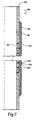
- Sand control screen assembly 60 includes a base pipe 62 that has a plurality of perforations 64 that allow for fluid production therethrough. Positioned about base pipe 62 is a sand control screen 66: Sand control screen 66 consists of a series of wire screen meshes. For example, sand control 66 may comprise five wire screen meshes, however, it is contemplated that the actual number of wire screen meshes utilized may vary from well to well.
- the mesh size used in sand control screen 66 will also vary from well to well depending upon the fluids to be produced, the rate of production, the geometry of the bore hole, the type of pipe string and the nature of the particles present in the formation. In general, the mesh size will range from about 10 to 250 U.S. Standard Mesh, however, any desired mesh sizes may be used.
- the wire screen meshes of sand control screen 66 be made from exotic alloys such as Incoloy 825 or Alloy 20Cb-3 or coated with chemicals such as corrosion inhibitors.
- environmental cracking is effectively neutralized by cathodic protection of the wire screen meshes of sand control screen 66.
- one or more of the wire screen meshes or even a single element of a wire screen mesh may be constructed from a metal that is cathodic to the metal used to construct the remainder of the wire screen meshes.
- the innermost wire screen mesh may be constructed from steel while the remainder of the wire screen meshes are constructed from 316L stainless steel.
- sand control screen assembly 60 has been described with sand control screen 66 placed between base pipe 62 and shroud 68 and perforated housing 70, sand control screen assembly 60 may also be provided in an embodiment in which shroud 68 and perforated housing 70 are not utilized. In such a case, sand control screen 66 may be secured to base pipe 62 using mechanical methods, spot welding or the like.
- Sand control screen assembly 80 includes a base pipe 82 having a plurality of perforations 84.
- Sand control screen assembly 80 also includes a plurality of ribs 86 that are symmetrically positioned about the axis of base pipe 82. Disposed about ribs 86 is a sand control screen 88.
- Sand control screen 88 is constructed from a porous sintered metal structure.
- the porous sintered metal structure is formed using metal powder particles that are metallurgically bonded at their contact points by a sintering operation.
- the space between the particles provide a continuous network of well defined pores whose size and distribution are dependent upon the particles and the processing methods.
- the size and distribution of the pores is selected based upon factors such as the fluid to be produced, the rate of production, the geometry of the bore hole, the type of pipe string and the nature of the particles present in the formation.
- turn 106 of wire 104 is disposed between turn 100 and turn 102 of screen wire 98.
- wire 104 may serve as the sacrificial anode for screen wire 98.
- wire 104 may be steel while screen wire 98 may be 316L stainless steel.
- the metal used for ribs 96 may either be steel or 316L stainless steel depending upon the expected rate of corrosion.
Landscapes
- Engineering & Computer Science (AREA)
- Geology (AREA)
- Life Sciences & Earth Sciences (AREA)
- Mining & Mineral Resources (AREA)
- Chemical & Material Sciences (AREA)
- Chemical Kinetics & Catalysis (AREA)
- Physics & Mathematics (AREA)
- Environmental & Geological Engineering (AREA)
- Fluid Mechanics (AREA)
- General Life Sciences & Earth Sciences (AREA)
- Geochemistry & Mineralogy (AREA)
- Dispersion Chemistry (AREA)
- Water Supply & Treatment (AREA)
- Prevention Of Electric Corrosion (AREA)
Claims (10)
- Ein Sandfiltersieb mit einen ersten Metall und einem zweiten Metall, welches mit dem ersten Metall einen elektrischen Kontakt aufrecht erhält, dadurch gekennzeichnet, dass das erste Metall aus einer Opferanode besteht, welche dem zweiten Metall aniodisch gegenüberliegt, wodurch ein umfeldbedingtes Brechen des Sandfiltersiebs verlangsamt werden kann.
- Ein Sandfiltersieb nach Anspruch 1, welches eine Reihe von Rippen (16) umfasst, welche um eine Achse herum angeordnet sind, wobei zumindest eine (26) der Rippen (16) das erste Metall umfasst; und einen Siebdraht (18), welcher um die Rippen (16) herum gewickelt ist und nebeneinander liegenden Schlaufen (20,22) mit Abständen zwischen denselben formt, wobei der Siebdraht (18) das zweite Metall umfasst, und wobei die oder jede Rippe (26), welche das erste Metall umfasst, aus einer Opferanode für denselben Siebdraht (18) besteht.
- Ein Sandfiltersieb nach Anspruch 2, bei welchem eine jede Schlaufe (20, 22) des Siebdrahtes (18) in elektrischem Kontakt mit der oder jeder der Rippen (26) steht, welche das erste Metall umfasst.
- Ein Sandfiltersieb nach Anspruch 1, 2 oder 3, bei welchem das zweite Metall Edelstahl umfasst.
- Ein Sandfiltersieb nach Anspruch 4, bei welchem der Edelstahl aus 316L Edelstahl besteht.
- Eine Methode für das Verlangsamen des umfeldbedingten Brechens eines Siebdrahtes (18) eines Sandfiltersiebs, welche die folgenden Stufen umfasst: das Wickeln des Siebdrahtes (18) um eine Reihe von Rippen (16), um auf diese Weise nebeneinander liegende Schlaufen (20, 22) mit Abständen zwischen denselben zu formen, wobei zumindest eine (26) der Rippen (16) ein erstes Metall umfasst, dadurch gekennzeichnet, dass der Siebdraht (18) ein zweites Metall umfasst, welches dem ersten Metall kathodisch gegenüberliegt; und dadurch gekennzeichnet, dass das umfeldbedingte Brechen des Siebdrahtes (18) mit Hilfe einer oder jeder der Rippen (26) verlangsamt wird, welche das erste Metall als eine Opferanode umfassen.
- Eine Methode nach Anspruch 6, welche weiter die Stufe des elektrischen Koppelns der Schlaufen (20, 22) des Siebdrahtes (18) mit einer oder jeder der Rippen (26) umfasst, welche das erste Metall umfassen.
- Eine Sandfiltersiebeinheit (10), welche das Folgende umfasst: ein Grundrohr (12); und ein Sandfiltersieb nach einem der obigen Ansprüche 1 bis 4, welches um das Grundrohr (12) herum angeordnet ist.
- Eine Sandfiltersiebeinheit (10) nach Anspruch 8, bei welcher das vorgenannte Sandfiltersieb eine Reihe von Drahtsiebnetzen umfasst.
- Eine Sandfiltersiebeinheit (10), bei welcher das Grundrohr über ein Gewinde mit einem Bohrgestänge verbunden werden kann.
Applications Claiming Priority (2)
| Application Number | Priority Date | Filing Date | Title |
|---|---|---|---|
| US71971 | 1998-05-04 | ||
| US09/071,971 US6092604A (en) | 1998-05-04 | 1998-05-04 | Sand control screen assembly having a sacrificial anode |
Publications (3)
| Publication Number | Publication Date |
|---|---|
| EP0955447A2 EP0955447A2 (de) | 1999-11-10 |
| EP0955447A3 EP0955447A3 (de) | 2000-09-13 |
| EP0955447B1 true EP0955447B1 (de) | 2004-03-17 |
Family
ID=22104760
Family Applications (1)
| Application Number | Title | Priority Date | Filing Date |
|---|---|---|---|
| EP99303160A Expired - Lifetime EP0955447B1 (de) | 1998-05-04 | 1999-04-23 | Sieb für Kontrolle von Sandproduktion mit kathodischem Korrosionsschutz |
Country Status (3)
| Country | Link |
|---|---|
| US (1) | US6092604A (de) |
| EP (1) | EP0955447B1 (de) |
| DE (1) | DE69915533T2 (de) |
Cited By (5)
| Publication number | Priority date | Publication date | Assignee | Title |
|---|---|---|---|---|
| WO2004065759A1 (en) * | 2003-01-15 | 2004-08-05 | Halliburton Energy Services, Inc. | Sand control screen assembly having an internal seal element and treatment method using the same |
| US6978840B2 (en) | 2003-02-05 | 2005-12-27 | Halliburton Energy Services, Inc. | Well screen assembly and system with controllable variable flow area and method of using same for oil well fluid production |
| US7055598B2 (en) | 2002-08-26 | 2006-06-06 | Halliburton Energy Services, Inc. | Fluid flow control device and method for use of same |
| US7096945B2 (en) | 2002-01-25 | 2006-08-29 | Halliburton Energy Services, Inc. | Sand control screen assembly and treatment method using the same |
| US7191833B2 (en) | 2004-08-24 | 2007-03-20 | Halliburton Energy Services, Inc. | Sand control screen assembly having fluid loss control capability and method for use of same |
Families Citing this family (32)
| Publication number | Priority date | Publication date | Assignee | Title |
|---|---|---|---|---|
| AU2001294412A1 (en) * | 2000-07-21 | 2002-02-05 | Sinvent A/S | Combined liner and matrix system, use of the system and method for control and monitoring of processes in a well |
| US6837308B2 (en) * | 2001-08-10 | 2005-01-04 | Bj Services Company | Apparatus and method for gravel packing |
| US6899176B2 (en) | 2002-01-25 | 2005-05-31 | Halliburton Energy Services, Inc. | Sand control screen assembly and treatment method using the same |
| US20040026313A1 (en) * | 2002-08-09 | 2004-02-12 | Arlon Fischer Todd Kenneth | Multi-micron, multi-zoned mesh, method of making and use thereof |
| EP1391593A1 (de) * | 2002-08-19 | 2004-02-25 | Perkins Engines Company Limited | Flüssigkeitsfiltrationssystem mit nachgebendem federnden Filter |
| US6886634B2 (en) | 2003-01-15 | 2005-05-03 | Halliburton Energy Services, Inc. | Sand control screen assembly having an internal isolation member and treatment method using the same |
| US6994170B2 (en) | 2003-05-29 | 2006-02-07 | Halliburton Energy Services, Inc. | Expandable sand control screen assembly having fluid flow control capabilities and method for use of same |
| US20050034860A1 (en) * | 2003-08-15 | 2005-02-17 | Lauritzen J. Eric | Screen for sand control in a wellbore |
| US20060070963A1 (en) * | 2004-10-04 | 2006-04-06 | Mckeary Leonard E | Method and apparatus for separating contaminants in fluids and gas |
| US7497257B2 (en) * | 2006-05-04 | 2009-03-03 | Purolator Facet, Inc. | Particle control screen with depth filtration |
| US7510011B2 (en) * | 2006-07-06 | 2009-03-31 | Schlumberger Technology Corporation | Well servicing methods and systems employing a triggerable filter medium sealing composition |
| CA2596094C (en) * | 2006-08-08 | 2011-01-18 | Weatherford/Lamb, Inc. | Improved milling of cemented tubulars |
| US7699101B2 (en) * | 2006-12-07 | 2010-04-20 | Halliburton Energy Services, Inc. | Well system having galvanic time release plug |
| US8196668B2 (en) * | 2006-12-18 | 2012-06-12 | Schlumberger Technology Corporation | Method and apparatus for completing a well |
| US20080289815A1 (en) * | 2007-05-22 | 2008-11-27 | Schlumberger Technology Corporation | Downhole screen assembly |
| US20100163481A1 (en) * | 2008-12-30 | 2010-07-01 | Dorstener Wire Tech | Drainage or Filter Layer for Well Screen Assembly with Integrated Stand-off Structure |
| US20100258302A1 (en) * | 2009-04-08 | 2010-10-14 | Halliburton Energy Services, Inc. | Well Screen With Drainage Assembly |
| US8146662B2 (en) * | 2009-04-08 | 2012-04-03 | Halliburton Energy Services, Inc. | Well screen assembly with multi-gage wire wrapped layer |
| US8251138B2 (en) | 2009-04-09 | 2012-08-28 | Halliburton Energy Services, Inc. | Securing layers in a well screen assembly |
| US8567498B2 (en) * | 2010-01-22 | 2013-10-29 | Schlumberger Technology Corporation | System and method for filtering sand in a wellbore |
| US8464793B2 (en) * | 2010-01-22 | 2013-06-18 | Schlumberger Technology Corporation | Flow control system with sand screen |
| US8291971B2 (en) | 2010-08-13 | 2012-10-23 | Halliburton Energy Services, Inc. | Crimped end wrapped on pipe well screen |
| US8490690B2 (en) | 2010-09-21 | 2013-07-23 | Halliburton Energy Services, Inc. | Selective control of flow through a well screen |
| RU2445146C1 (ru) * | 2010-10-01 | 2012-03-20 | Александр Владимирович Яшин | Щелевой фильтр |
| US8701757B2 (en) | 2010-12-17 | 2014-04-22 | Halliburton Energy Services, Inc. | Sand control screen assembly having a compliant drainage layer |
| US9267360B2 (en) | 2011-04-01 | 2016-02-23 | Schlumberger Technology Corporation | Premium mesh screen |
| US9428989B2 (en) | 2012-01-20 | 2016-08-30 | Halliburton Energy Services, Inc. | Subterranean well interventionless flow restrictor bypass system |
| US20140151287A1 (en) * | 2012-12-03 | 2014-06-05 | Omar H. Balcazar | Screen and method of making the same |
| MX365339B (es) * | 2013-03-04 | 2019-05-30 | Halliburton Energy Services Inc | Utilización de almohadillas filtradas para filtrar muestras de formación no consolidada. |
| WO2015195099A1 (en) * | 2014-06-17 | 2015-12-23 | Halliburton Energy Services, Inc. | Sacrificial screen shroud |
| US9702228B2 (en) * | 2014-09-04 | 2017-07-11 | Baker Hughes Incorporated | Porous structure for downhole fluid control applications and method of manufacture |
| AU2015382439B2 (en) * | 2015-02-13 | 2018-08-02 | Halliburton Energy Services, Inc. | Sand control screen assemblies with erosion-resistant flow paths |
Family Cites Families (13)
| Publication number | Priority date | Publication date | Assignee | Title |
|---|---|---|---|---|
| US1646735A (en) * | 1924-07-21 | 1927-10-25 | Peter Q Nyce | Electrochemical method for preventing corrosion |
| US2801697A (en) * | 1953-08-03 | 1957-08-06 | Crest Res Lab Inc | Methods and means for introducing corrosion inhibitors into oil wells |
| US3277966A (en) * | 1963-11-01 | 1966-10-11 | Warren F Ward | Guide with sacrificial inserts |
| US4102395A (en) * | 1977-02-16 | 1978-07-25 | Houston Well Screen Company | Protected well screen |
| US4211625A (en) * | 1978-09-11 | 1980-07-08 | Borg-Warner Corporation | Impressed current cathodic protection system for submersible downhole pumping assembly |
| US4688828A (en) * | 1986-04-02 | 1987-08-25 | Shaffer Donald U | Tubing joint for corrosion protection |
| US5004049A (en) * | 1990-01-25 | 1991-04-02 | Otis Engineering Corporation | Low profile dual screen prepack |
| US5190102A (en) * | 1990-10-22 | 1993-03-02 | Otis Engineering Corporation | Sintered metal substitute for prepack screen aggregate |
| US5070533A (en) * | 1990-11-07 | 1991-12-03 | Uentech Corporation | Robust electrical heating systems for mineral wells |
| US5310000A (en) * | 1992-09-28 | 1994-05-10 | Halliburton Company | Foil wrapped base pipe for sand control |
| US5355956A (en) * | 1992-09-28 | 1994-10-18 | Halliburton Company | Plugged base pipe for sand control |
| GB9319036D0 (en) * | 1993-09-14 | 1993-10-27 | Overseas Water Services Limite | Improved pre-pack well tube |
| US5829522A (en) * | 1996-07-18 | 1998-11-03 | Halliburton Energy Services, Inc. | Sand control screen having increased erosion and collapse resistance |
-
1998
- 1998-05-04 US US09/071,971 patent/US6092604A/en not_active Expired - Fee Related
-
1999
- 1999-04-23 EP EP99303160A patent/EP0955447B1/de not_active Expired - Lifetime
- 1999-04-23 DE DE69915533T patent/DE69915533T2/de not_active Expired - Fee Related
Cited By (7)
| Publication number | Priority date | Publication date | Assignee | Title |
|---|---|---|---|---|
| US7096945B2 (en) | 2002-01-25 | 2006-08-29 | Halliburton Energy Services, Inc. | Sand control screen assembly and treatment method using the same |
| US7055598B2 (en) | 2002-08-26 | 2006-06-06 | Halliburton Energy Services, Inc. | Fluid flow control device and method for use of same |
| WO2004065759A1 (en) * | 2003-01-15 | 2004-08-05 | Halliburton Energy Services, Inc. | Sand control screen assembly having an internal seal element and treatment method using the same |
| GB2413817A (en) * | 2003-01-15 | 2005-11-09 | Halliburton Energy Serv Inc | Sand control screen assembly having an internal seal element and treatment method using the same |
| GB2413817B (en) * | 2003-01-15 | 2007-01-10 | Halliburton Energy Serv Inc | Sand control screen assembly having an internal seal element and treatment method using the same |
| US6978840B2 (en) | 2003-02-05 | 2005-12-27 | Halliburton Energy Services, Inc. | Well screen assembly and system with controllable variable flow area and method of using same for oil well fluid production |
| US7191833B2 (en) | 2004-08-24 | 2007-03-20 | Halliburton Energy Services, Inc. | Sand control screen assembly having fluid loss control capability and method for use of same |
Also Published As
| Publication number | Publication date |
|---|---|
| EP0955447A3 (de) | 2000-09-13 |
| DE69915533D1 (de) | 2004-04-22 |
| DE69915533T2 (de) | 2004-08-05 |
| EP0955447A2 (de) | 1999-11-10 |
| US6092604A (en) | 2000-07-25 |
Similar Documents
| Publication | Publication Date | Title |
|---|---|---|
| US6092604A (en) | Sand control screen assembly having a sacrificial anode | |
| Garverick | Corrosion in the petrochemical industry | |
| CA2939257C (en) | Isolation devices having an anode matrix and a fiber cathode | |
| US4170532A (en) | Deep well platinized anode carrier for cathodic protection system | |
| US20200032625A1 (en) | Degradable Metal Barrier For Downhole Screens | |
| CA2106922A1 (en) | Plugged base pipe for sand control | |
| US20190309405A1 (en) | Corrosion resistant thermal spray alloy | |
| CA3016238A1 (en) | System and method for cathodic protection by distributed sacrificial anodes | |
| KR20010030856A (ko) | 음극 보호 방법 및 장치 | |
| AU7042194A (en) | Sand screen structure | |
| Turgoose et al. | Preferential weld corrosion of 1% Ni welds: effect of solution conductivity and corrosion inhibitors | |
| US6331242B1 (en) | Anodic encasement corrosion protection system for underground storage tanks, and metallic components thereof | |
| US4964966A (en) | Electrode and construction thereof | |
| CN104976438B (zh) | 用于复合金属管的外端管及其制造方法 | |
| US7186327B1 (en) | Method and apparatus for scaling control and in-situ cathodic protection | |
| US20180238150A1 (en) | Sand Control Screen Assemblies and Associated Methods of Manufacturing | |
| US10808164B2 (en) | Corrosion inhibition | |
| RU2468126C1 (ru) | Способ изготовления нерастворимого анода на титановой основе | |
| Baboian | Miniaturised impressed current corrosion protection systems | |
| EP4058655A1 (de) | Vorrichtung mit einem auflösbaren material zur verwendung in einem bohrloch | |
| Kroon et al. | Performance of impressed current anodes for cathodic protection underground | |
| CN100390323C (zh) | 半导体腐蚀和污染控制设备,系统和方法 | |
| Mohamed et al. | Improve Sacrificial Anodes to Impressed Current in Puma Energy PNG Limited Throughout the Country | |
| WO2026087006A1 (en) | Feedthrough device for high-temperature moeten saet environments, use of a feedthrough device and an eeectrochemicae sensor device | |
| JPH0242910B2 (de) |
Legal Events
| Date | Code | Title | Description |
|---|---|---|---|
| PUAI | Public reference made under article 153(3) epc to a published international application that has entered the european phase |
Free format text: ORIGINAL CODE: 0009012 |
|
| AK | Designated contracting states |
Kind code of ref document: A2 Designated state(s): DE FR GB NL |
|
| AX | Request for extension of the european patent |
Free format text: AL;LT;LV;MK;RO;SI |
|
| RIN1 | Information on inventor provided before grant (corrected) |
Inventor name: YOUNGBERG, LON T. Inventor name: RICE, PATRICK W. |
|
| PUAL | Search report despatched |
Free format text: ORIGINAL CODE: 0009013 |
|
| AK | Designated contracting states |
Kind code of ref document: A3 Designated state(s): AT BE CH CY DE DK ES FI FR GB GR IE IT LI LU MC NL PT SE |
|
| AX | Request for extension of the european patent |
Free format text: AL;LT;LV;MK;RO;SI |
|
| RIC1 | Information provided on ipc code assigned before grant |
Free format text: 7E 21B 43/08 A, 7E 21B 41/02 B |
|
| 17P | Request for examination filed |
Effective date: 20010302 |
|
| AKX | Designation fees paid |
Free format text: DE FR GB NL |
|
| 17Q | First examination report despatched |
Effective date: 20021211 |
|
| GRAP | Despatch of communication of intention to grant a patent |
Free format text: ORIGINAL CODE: EPIDOSNIGR1 |
|
| GRAS | Grant fee paid |
Free format text: ORIGINAL CODE: EPIDOSNIGR3 |
|
| GRAA | (expected) grant |
Free format text: ORIGINAL CODE: 0009210 |
|
| AK | Designated contracting states |
Kind code of ref document: B1 Designated state(s): DE FR GB NL |
|
| REG | Reference to a national code |
Ref country code: GB Ref legal event code: FG4D |
|
| REF | Corresponds to: |
Ref document number: 69915533 Country of ref document: DE Date of ref document: 20040422 Kind code of ref document: P |
|
| PGFP | Annual fee paid to national office [announced via postgrant information from national office to epo] |
Ref country code: NL Payment date: 20040427 Year of fee payment: 6 Ref country code: FR Payment date: 20040427 Year of fee payment: 6 |
|
| PGFP | Annual fee paid to national office [announced via postgrant information from national office to epo] |
Ref country code: DE Payment date: 20040506 Year of fee payment: 6 |
|
| ET | Fr: translation filed | ||
| PLBE | No opposition filed within time limit |
Free format text: ORIGINAL CODE: 0009261 |
|
| STAA | Information on the status of an ep patent application or granted ep patent |
Free format text: STATUS: NO OPPOSITION FILED WITHIN TIME LIMIT |
|
| 26N | No opposition filed |
Effective date: 20041220 |
|
| PG25 | Lapsed in a contracting state [announced via postgrant information from national office to epo] |
Ref country code: NL Free format text: LAPSE BECAUSE OF NON-PAYMENT OF DUE FEES Effective date: 20051101 Ref country code: DE Free format text: LAPSE BECAUSE OF NON-PAYMENT OF DUE FEES Effective date: 20051101 |
|
| PG25 | Lapsed in a contracting state [announced via postgrant information from national office to epo] |
Ref country code: FR Free format text: LAPSE BECAUSE OF NON-PAYMENT OF DUE FEES Effective date: 20051230 |
|
| NLV4 | Nl: lapsed or anulled due to non-payment of the annual fee |
Effective date: 20051101 |
|
| REG | Reference to a national code |
Ref country code: FR Ref legal event code: ST Effective date: 20051230 |
|
| PGFP | Annual fee paid to national office [announced via postgrant information from national office to epo] |
Ref country code: GB Payment date: 20070313 Year of fee payment: 9 |
|
| GBPC | Gb: european patent ceased through non-payment of renewal fee |
Effective date: 20080423 |
|
| PG25 | Lapsed in a contracting state [announced via postgrant information from national office to epo] |
Ref country code: GB Free format text: LAPSE BECAUSE OF NON-PAYMENT OF DUE FEES Effective date: 20080423 |