EP0955178A2 - Print ribbon feeder and detection system - Google Patents
Print ribbon feeder and detection system Download PDFInfo
- Publication number
- EP0955178A2 EP0955178A2 EP99303524A EP99303524A EP0955178A2 EP 0955178 A2 EP0955178 A2 EP 0955178A2 EP 99303524 A EP99303524 A EP 99303524A EP 99303524 A EP99303524 A EP 99303524A EP 0955178 A2 EP0955178 A2 EP 0955178A2
- Authority
- EP
- European Patent Office
- Prior art keywords
- ribbon
- spool
- spools
- angular velocity
- motor means
- Prior art date
- Legal status (The legal status is an assumption and is not a legal conclusion. Google has not performed a legal analysis and makes no representation as to the accuracy of the status listed.)
- Withdrawn
Links
Images


Classifications
-
- B—PERFORMING OPERATIONS; TRANSPORTING
- B41—PRINTING; LINING MACHINES; TYPEWRITERS; STAMPS
- B41J—TYPEWRITERS; SELECTIVE PRINTING MECHANISMS, i.e. MECHANISMS PRINTING OTHERWISE THAN FROM A FORME; CORRECTION OF TYPOGRAPHICAL ERRORS
- B41J33/00—Apparatus or arrangements for feeding ink ribbons or like character-size impression-transfer material
- B41J33/14—Ribbon-feed devices or mechanisms
- B41J33/36—Ribbon-feed devices or mechanisms with means for adjusting feeding rate
Definitions
- the field of this invention pertains to printers and particularly those printers that have ribbons that are impacted for printing on paper or other media.
- it is known to drive a ribbon from two spools.
- one end of the ribbon is connected to a spool driven by a motor in a winding or take-up mode.
- the other portion of the ribbon is connected to a spool in a feed mode.
- This invention particularly relates to emplacing the ribbon with a clean non-inked leader or portion and then appropriately driving it.
- This invention is particularly adapted to ribbon drives for impact printers.
- Such impact printers can be dot matrix printers and more specifically line type printers.
- Such line printers are known in the art and have been developed extensively by the assignee of this invention.
- the inked ribbons of such various printers are repeatedly impacted against a length of print paper or other printable medium by certain impact elements.
- the impact elements can each define a shape or a character or simply print dots, with characters or other indicia to be printed being formed in a dot matrix fashion.
- Such dot matrix printers can be of the line printer type in which a plurality of hammers or other impact printing mechanisms are mounted along the length of a hammerbank. They are driven by a shuttle assembly and are selectively actuated to impact the print paper. The impact is through a length of inked ribbon. This prints dots on the paper as the shuttle assembly is caused to undergo reciprocating motion relative to the paper.
- the inked ribbon extends through the print station and has the opposite ends thereof wound upon an opposite pair of spools.
- the opposite spools of the ribbon drive are rotatably driven to provide continuous motion of the length of ribbon through the print station.
- the direction of drive of the spools is reversed. This causes the ribbon to move through the print station in the opposite direction.
- a pair of two phase stepper motors control the tension and the velocity of the print ribbon between two spools. At any given time during printing, one motor pulls ribbon through the print station at a substantial constant velocity while the second motor is run in a regenerative mode to provide tension. When the ribbon reaches the end of it's travel in any given direction, it's direction is reversed so that the function of the two respective motors and spools are then reversed.
- the angular velocity of the feed motor or motor attached to the spool from which the ribbon is unwinding is calculated by counting the number of zero crossings on the back EMF waveform. In any given period of time the angular velocity of the take-up motor is set by the system micro controller.
- the ratio of the angular velocities of the feed take-up spool or reel is a unique number over the range of ribbon radii in the system.
- the radius of the ribbon material on each reel can be determined at set intervals based upon the ratio of the angular velocities. This ratio information used to determine the angular velocity and tension is updated at any given time.
- a major problem with regard to loading the inked ribbon into a printer is the fact that the ribbon itself has ink which can be imparted to any surface which it touches. This is particularly true with regard to a user's hands. When handling the ribbon, users often times find their hands very dirty as well as various portions of the equipment.
- the invention hereof provides for a printer ribbon having a clean hands portion formed of an electrically conductive plastic or other material that can be monitored with respect to the interface at which it is connected to the inked portion of the ribbon. This allows a user and installer of the ribbon to emplace the ribbon by merely handling the non-inked portions and emplacing it over the spools or spindles which are driven by the motors. Thereafter, the system of this invention detects where the non-inked portion is and determines at a particular juncture or interface of the non-inked portion and the inked portion when and where printing can begin.
- An object of this invention is to permit the loading of an inked ribbon into a printer without smudging or soiling a user or the surrounding area in which the ribbon is loaded.
- Another object of this invention is to allow for a clean type of ribbon leader to be emplaced in a printer on a relatively automated basis.
- a further object of this invention is to allow a print ribbon to be emplaced within a printer and not create a soiling condition for an operator while at the same time allowing an operator to avoid having to handle the ribbon after it has been emplaced for positioning with respect to the printing functions.
- Another object of this invention is to automatically detect a position of a clean ribbon leader with respect to the inked print ribbon so that printing can commence with respect to the inked ribbon portions on an automated basis.
- An important final object of this invention is to allow a print ribbon to be emplaced in a printer with clean leaders extending therefrom and a detection of the position of the clean leaders to effect automated startup of printing functions after emplacement of the ribbon in the printer.
- this invention is a system and apparatus for emplacing a print ribbon in a printer having two spools which drive the ribbon in each direction wherein the print ribbon has a non-inked portion that can be handled by a user and emplaced in the printer and loaded without soiling and thereafter allowing the printer to automatically determine the position of the print ribbon with respect to the non-inked portion.
- the invention comprises a printer having two spools or spindles each driven by motors.
- the ribbon emplaced in the printer has a conductive plastic material portion at either end wound around a spool sufficiently to avoid soiling contact with a user's hand upon loading, or the surrounding area.
- the conductive plastic is particularly utilized for emplacement without soil while at the same time providing conductivity over a pair of sensing bars or posts to determine ribbon position.
- the ribbon After emplacement the ribbon is then tensioned and driven sufficiently to provide for orientation of the inked portion with respect to the non-inked conductive plastic portion.
- the relative position of the ribbon as to a substantially full spool or a comparatively empty spool is then determined by driving the motors to determine the angular velocity of the spools.
- the angular velocity of the smaller spool or that which is not substantially wound with ribbon is greater than that of the fully wound spool. This then allows the processor of the invention to determine the particular spool which has the larger and smaller of the two respective amounts of ribbon.
- the inked ribbon is then driven in the proper direction to cause it to be wound onto the spool having the lesser print ribbon while being dragged from the spool having the greater amount of print ribbon.
- this invention allows for emplacement of the ribbon without further action and while at the same time automatically providing for orientation and driving of the ribbon in the right direction from the substantially full spool to the take-up spool.
- Figure 1 shows a perspective view of a print ribbon of this invention being loaded into a printer.
- Figure 2 shows the print ribbon of this invention with the conductive clean portion of the print ribbon exposed as it is being emplaced in the printer.
- Figure 3 shows the conductive clean portion of the print ribbon attached to the inked portion as it passes over a detector.
- Figure 4 shows a detailed perspective view of the ribbon on a spool viewed from the right hand side of Figure 1.
- Figure 5 shows a schematic view of the circuitry and logic of this invention with respect to the printer.
- Figure 6 shows a view of the print ribbon being driven on the respective spools.
- Figure 7 shows a detailed sectional view of the print ribbon passing through the print station with the hammerbanks and platen in associated relationship therewith as sectioned along lines 7-7 of Figures 1 and 2.
- Figure 8 shows a block diagram of the respective logic of the sensing functions of the system with respect to the positioning of the print ribbon.
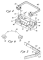
- Figure 1 shows a printer 10 of the type known as a dot matrix line printer. A ribbon is shown being emplaced in the printer attached to two spools which will be detailed hereinafter.
- the printer includes an elongated hammerbank 12 hidden from view.
- the hammerbank 12 is mounted and driven in a reciprocating manner by a shuttle drive.
- the hammerbank reciprocates with respect to a platen 16 as seen in Figure 7 sectioned from lines 7-7 of Figures 1 and 2.
- the space between the hammerbank 12 and the platen 16 defines a print station 18. This is more easily seen in Figure 7.
- the print paper 20 is advanced upwardly through the print station 18 by two tractor drives 24 and 26 on opposite sides of the printer.
- the tractor drives 24 and 26 move the paper 20 upwardly as each row of dots is printed thereacross.
- the ribbon 22 extends along the length of the print station 18 and has the opposite ends thereof wound on two opposite pairs of reels or spools 28 and 30. Spools 28 and 30 are connected to the ribbon drive 32 at the lower end of the printer 10.
- the ribbon drive 32 is shown in an exploded form in Figure 2.
- the opposite spools 28 and 30 are removably mounted on spindles 34 and 36.
- Spindles 34 and 36 are connected to the stepper motors which shall be detailed hereinafter as to the motors and the control system.
- stepper motors which shall be detailed hereinafter as to the motors and the control system.
- guide 38 In order to properly dispose the ribbon 22 within the print station 18 it is facilitated by a pair of guides mounted on opposite ends, one of which is shown as guide 38 in Figures 1, 2, and 4.
- the other guide which is a mirror image of guide 38 is hidden from view in part.
- the ribbon 22 is driven by the stepper motors turning the spindles 34 and 36.
- the speed of the print ribbon 22 can vary depending upon the type of printing conditions required. Generally, the print ribbon 22 is advanced in one direction such as from the spool 30 to the spool 28 and then reversed thereafter.
- the hammerbank 12 seen in Figure 7 extends from the opposite ends to a mount for the hammerbank 12 to provide reciprocating motion.
- a plurality of resiliently flexible hammer springs 42 are shown.
- the hammer springs 42 are mounted along a length of the hammerbank 12 such that a lower end 44 of each spring 42 is secured to a base 46. An opposite upper end 48 of each hammer spring 42 is free to move with the flexure of the spring 42.
- the springs 42 are magnetically held in a retracted position against pole pieces 50 mounted within a frame 54 of the hammerbank 12.
- a pair of coils are mounted on the pole pieces 50.
- a permanent magnet is disposed between them and within the frame 54.
- the upper end 48 of the hammer spring 42 is normally held in a retracted position against the pole pieces 50 by the permanent magnet forming a magnetic circuit therewith.
- the coils When the coils are momentarily energized, it overcomes the magnetic force and releases the hammer spring 42 from its retracted position causing dots to be printed on the paper 20 by a dot printing impact tip 62. Afterwards, the spring 42 rebounds into the retracted position against the pole pieces 50.
- a thin planar hammerbank cover 64 is mounted on the base 46 of the hammerbank.
- a thin planar paper ironer 68 of resilient material is disposed between the paper 20 and the hammerbank cover 64. This resiliently bears against the paper 20 to create a drag and hold the paper under tension as it is advanced upwardly by the opposing tractor drives 24 and 26.
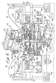
- two stepper motors 86 and 88 are shown connected to the spindles 34 and 36.
- the stepper motors 86 and 88 are connected to the controller circuitry of the invention as shown generally by the lead lines 90 and 92.
- Lines 90 and 92 are deemed to be for descriptive purposes only inasmuch as the respective stepper motors comprise a first and second series of poles for two phase operation.
- the first and second series of poles can be in any multiple even series such as 8 or 16. They are connected to the respective lines shown hereinafter with respect to their connection to full H bridge drivers.
- lines 77 and 79 connect a first phase for motor 86, while lines 81 and 83 connect a second phase.
- Lines 85 and 87 connect a first phase for motor 88, while lines 89 and 91 connect a second phase.
- the two phase stepper motors are connected to the two ribbon spools 28 and 30 by spindles 34 and 36.
- one of the two motors 86 or 88 provides the drive torque or take-up to pull the ribbon 22 through the print station 18. While this is happening the other motor provides the required tension to the feed spool to maintain proper ribbon tracking through its drag action. When the end of the ribbon 22 is reached the functions of the two respective motors 86 and 88 are reversed.
- motor 86 is providing the drive torque to take-up and pull the ribbon 22 across the print station 18.
- One phase of the motor 86 is driven through lines 77 and 79 by a full H bridge 94 connected to a pulse width modulator (pwm) generator 96.
- the duty cycle of the pulse width modulator generator 96 is determined by a digital number loaded into the latch 98 by the system micro controller 100.
- the pwm generator 96 can be substituted with any type of linear amplifier. Also, analog or digital control functions can serve to regulate the drivers.
- phase referred to as a quadrature phase is driven through lines 81 and 83 by another full H bridge 102 connected to another pwm generator 104 or in the alternative, a linear amplifier.
- the duty cycle thereof is also determined by the system micro controller 100.
- resistor banks 106 and 108 are held in a tri-state mode by the system micro controller 100 via the address decode input output latch 110. This effectively disconnects the resistor banks 106 and 108 from the output circuit of the full H bridges 102 and 94, or in the alternative variable resistance amplifiers substituted for the resistor banks.
- the reason why the resistors 106 and 108 are disconnected is to prevent any load being applied to the drive motor amplifier.
- the load when applied is for creating a drag as will be seen in the drag relationship of the motor 88 in its re-generative mode.
- the other resistor bank is symmetrical in function to the resistors 106 and 108.
- variable resistor bank In lieu of a variable resistor bank, a load bank or variable impedance amplifier can be used. Also a highly advantageous method is to short the motor coils for variable durations to create a load or resistance. In many cases this is preferable to a separate and independent load resistor bank.
- the micro controller 100 updates the duty cycle of the pwm generators 96 and 104 in a manner that the vector sum of the torques of the two phases created by the resultant current profiles is a constant. This provides a constant torque drive.
- the micro controller 100 logic reduces the angular velocity of the motor 86 to maintain a constant linear velocity of the ribbon 22 across the print station 18. This is through the update provided by pulse width modulation generators 120 and 122 or linear amplifiers at the appropriate times in a manner to be described hereinafter through the zero crossing and edge triggered circuitry connected to the motor 88 in the re-generative mode serving as a drag motor.
- the pulse width modulator generators 120 and 122 can be substituted by any suitable type of linear amplifier.
- the micro controller 100 updates the pwm generators 96 and 104 in a manner that maintains a constant peak current which is established through the H bridges 94 and 102 in the 90 degree phased manner shown in block 114.
- a retarding torque is provided in the given mode shown by motor 88 when the ribbon- 22 is unwinding, and when motor 86 is providing take-up or winding torque.
- the full H bridges 124 and 126 are held in a tri-state mode by the micro controller 100 logic through the address decode of input output latch 110. The result is to effectively disconnect bridges 124 and 126 from the motor 88.
- the load banks or resistors 130 and 132 are connected to the windings of motor 88.
- the back emf voltage across the two phases of motor 88 can be seen in the lag of the voltages in a 90 degree manner shown in block 133. These back emf voltages are applied to the respective load banks provided by resistors 130 and 132.
- variable impedance amplifier can be substituted for each variable resistor, or load bank as the case may be.
- motor windings can be shorted for variable durations to provide a resistance through the windings to increase or decrease drag.
- the controller 100 reduces the load on the resistance bank which is comprised of resistors 130 and 132 connected to the two phases of motor 88 or the controller varies the shorting of the motor coils to provide the appropriate loading for drag.
- a zero detection circuit 136 is connected across one winding of the motor 88. This creates a pulse width duration corresponding to the positive half cycle of the back electromotive force (BEMF) of the motor 88 while operating in the regenerative mode.
- BEMF back electromotive force
- This signal is fed into the edge triggered one-shot 138 which creates a pulse for each edge of the half cycle pulse.
- the signal can be seen in the box 150 provided by the zero crossing detector as it feeds into the edge triggered one-shot 138 providing a one-shot output shown in box 152.
- the output of the edge triggered one-shot 138 as shown by the waveform in box 152 is then counted by a counter 140.
- the motor 86 Since the motor 86 is providing a drive or take-up torque, the signals from its corresponding zero crossing detector 142 and a one-shot 144 are ignored by the counter 140.
- the angular velocity of the drive motor 86 is determined by the controller 100 which is provided with the equivalent electrical zero crossing counts of the motor 88.
- the ratio of the counts of the zero crossings is a unique number from which the radii of the ribbon 22 material on each reel can be calculated.
- the controller 100 periodically checks and resets the counter 140. The resulting ratio information is used to alter the drive frequency of the motor 86 to maintain constant linear print ribbon velocity across the print station 18 as well as to alter the loading on motor 88 to maintain proper ribbon tension.
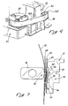
- an elongated conductive plastic strip 160 attached to the ribbon 22 passes over the ribbon guide 38.
- the elongated conductive plastic strip is approximately 5 to 10 feet long and serves the function of a clean ribbon portion or ribbon without ink.
- a reversal is signaled. This is caused by the conductive strip 160 shorting two bars 161 and 162 connected to a detection circuit shown as circuit 164.
- the full H bridges 102 and 94 as well as the load banks 130 and 132 are inactivated.
- the signals from the respective edge triggered one-shot and the zero crossing detector are ignored.
- the signals from the zero crossing detector 142 and the edge triggered one-shot 144 are then processed.
- the load banks 106 and 108 as well as the full H bridge drivers 124 and 126 in their alternative mode are activated after an appropriate time delay.
- the time delay is established within the micro controller 100 logic to allow a ringing out or settling of the electronics. At such time, the respective take-up and feed motors 86 and 38 apply a degree of tension on the print ribbon 22 to tension it sufficiently across the print station 18.
- the spool or reel 28 then becomes the feed spool with motor 86 operating in the regenerative mode.
- Spool or reel 30 then becomes the take-up spool or reel with motor 88 operating in the drive or take-up mode until the opposite reversal or elongated clean ribbon strip 160 is sensed by the ribbon guide in connection with the left side of the printer.
- a clock 200 is provided to the circuit.
- the clock 200 goes into a clock output (cko) line 202.
- a watch dog circuit 204 is provided which shuts down the entire printer when a failure mode is detected through the micro controller 100 logic.
- the two phased stepper motors 86 and 88 are driven by the pulse width modulated sine waves generated by a micro controller which is the micro controller 100 in conjunction with the custom mechanical driver or ASIC.
- the print ribbon that is the inked portion namely inked portion 22 as connected to the conductive plastic portion 160 it can be seen in Figure 3 that they are joined.
- the joining can be in any particular manner with a bonding adhesive or weldment.
- gluing a strip on either side in order to hold them together at their abutting interface can be utilized.
- the electrically conductive plastic of the ribbon 160 can be of any type of conductive plastic or other material which is known in the art including Mylar and other plastics having certain conductivity that can be imparted thereto. This electrical conductivity allows for the functions that will be detailed hereinafter.
- This electrically conductive Mylar portion of the print ribbon or the metalized portion is shown as portion 160 in Figure 2 and can be seen as wrapped around the spools at the point of installation.
- the Mylar print ribbon portion 160 is also shown as the only exposed portion of the print ribbon. The entire print ribbon as exposed is only formed of the electrically conductive Mylar ribbon portion 160. This provides the clean portion to avoid soiling the installer's hands or surrounding area.
- the ribbon when being loaded is exposed as only the Mylar ribbon or tape portion 160 which shall be called the clean ribbon segment or clean hands portion.
- the clean ribbon segment hereinafter shall refer to that portion of the conductive plastic or any other leader material which does not have printing ink thereon.
- This portion of the ribbon is wound around the relatively empty take-up spool and the other spool so that only the clean ribbon or clean hands portion 160 is exposed.
- the surrounding area is not soiled with printing ink.
- Figure 5 shows the controlling and drive functions of the printer 10. These are fundamentally part of an engine controller (EC) which establishes the overall control functions.
- the data controller (DC) is also mounted on a controller board on which the engine controller (EC) is mounted.
- a host as in all cases, drives the controller board that includes the engine controller (EC) and the data controller (DC).
- the engine controller (EC) will test for a clean hands ribbon during power up or whenever a fault is cleared. This is detailed hereinafter by the logic diagram of Figure 8.
- a clear fault command is sent from the data controller (DC) to the engine controller (EC)
- the following steps are undertaken in order to ascertain the orientation of the print ribbon and spools having been installed as well as the fact that they have been installed. It should be born in mind that this system will allow for both totally inked ribbons as well as ribbons with the clean ribbon leaders or clean hands portion 160 connected thereto.
- the engine controller (EC) After installation, the engine controller (EC) will wait a period of two seconds. This period allows the user enough time to move his or her hands off of a platen lever namely the lever which is connected to platen 16. The engine controller (EC) will then open the platen 16. Thereafter, the engine controller (EC) will provide tension to the print ribbon by driving both spools 28 and 30 in their normally driven position for a half a second. When the ribbon is driven and put in tension and pulled in opposite directions for a half a second, it places it into a proper orientation with respect to the ribbon guides 38.
- the engine controller (EC) will then check the two shorting bars 161 and 162 of each guide 38 (left and right) which can be referred to as ribbon posts.
- the engine controller (EC) will then check the two shorting bars 161 and 162 of each guide 38 (left and right) which can be referred to as ribbon posts.
- a determination is made as to whether or not ribbon posts 161 and 162 have been shorted by the conductive metallic ribbon 160 passing thereover and being in contact therewith.
- This shorting of the ribbon posts 161 and 162 causes a determination to be made that in point there is a metallic bridge or conductive tape portion 160 thereacross.
- the ribbon posts 161 and 162 are checked a total of three times because of possible discrepancies in contact which might have occurred.
- the engine controller (EC) will then drive the ribbon in one direction for approximately one second. Thereafter, it will drive the ribbon in the other direction for approximately one second.
- the zero drag crossings of the zero crossing detector 136 in the two directions will be compared within the micro controller 100 logic. A comparison is made of the respective spools 28 or 30.
- the spool having the least amount of ribbon whether it be inked print ribbon 22 or the clean hands ribbon 160 will be moving at the higher of the two angular velocities.
- the one with the greater amount of print ribbon 160 or 22 thereon will be moving at a slower angular velocity. This determines that the one with the less print ribbon (i.e. the one of higher angular velocity movement) should be the take-up spool, while the other one should be the feed spool.
- the engine controller will then drive the smaller spool and drag the larger spool. No speed adjustment updates are processed as during normal printing during this special drive sequence. Throughout the drive sequence since the angular speed is not precisely known, zero drag will be applied to the dragging or feed spool.
- clean hands ribbon portion 160 can be detected by other means.
- guides 38 and detectors 161 and 162 can be substituted with optical sensors to determine the relative opacity, reflectivity or other variations between the inked ribbon portion 22 and the clean hands portion 160.
- optical ports or openings in the clean hands ribbon portion 160 can be provided so that a beam of light can be read when this portion passes an optical sensor or reader.
- this invention is a substantial step in the art of clean ribbon emplacement. This invention then provides a systematic approach of determining the particular spool that should be driven without operator intervention, all of which should be broadly recognized under the following claims.
Landscapes
- Impression-Transfer Materials And Handling Thereof (AREA)
Abstract
Description
- The field of this invention pertains to printers and particularly those printers that have ribbons that are impacted for printing on paper or other media. In such printers, it is known to drive a ribbon from two spools. Generally, one end of the ribbon is connected to a spool driven by a motor in a winding or take-up mode. The other portion of the ribbon is connected to a spool in a feed mode. This invention particularly relates to emplacing the ribbon with a clean non-inked leader or portion and then appropriately driving it.
- This invention is particularly adapted to ribbon drives for impact printers. Such impact printers can be dot matrix printers and more specifically line type printers. Such line printers are known in the art and have been developed extensively by the assignee of this invention.
- The inked ribbons of such various printers are repeatedly impacted against a length of print paper or other printable medium by certain impact elements. The impact elements can each define a shape or a character or simply print dots, with characters or other indicia to be printed being formed in a dot matrix fashion.
- Such dot matrix printers can be of the line printer type in which a plurality of hammers or other impact printing mechanisms are mounted along the length of a hammerbank. They are driven by a shuttle assembly and are selectively actuated to impact the print paper. The impact is through a length of inked ribbon. This prints dots on the paper as the shuttle assembly is caused to undergo reciprocating motion relative to the paper.
- The inked ribbon extends through the print station and has the opposite ends thereof wound upon an opposite pair of spools. During printing, the opposite spools of the ribbon drive are rotatably driven to provide continuous motion of the length of ribbon through the print station. When the end of the ribbon is reached the direction of drive of the spools is reversed. This causes the ribbon to move through the print station in the opposite direction.
- A pair of two phase stepper motors control the tension and the velocity of the print ribbon between two spools. At any given time during printing, one motor pulls ribbon through the print station at a substantial constant velocity while the second motor is run in a regenerative mode to provide tension. When the ribbon reaches the end of it's travel in any given direction, it's direction is reversed so that the function of the two respective motors and spools are then reversed.
- The angular velocity of the feed motor or motor attached to the spool from which the ribbon is unwinding, is calculated by counting the number of zero crossings on the back EMF waveform. In any given period of time the angular velocity of the take-up motor is set by the system micro controller. The ratio of the angular velocities of the feed take-up spool or reel is a unique number over the range of ribbon radii in the system. The radius of the ribbon material on each reel can be determined at set intervals based upon the ratio of the angular velocities. This ratio information used to determine the angular velocity and tension is updated at any given time.
- A major problem with regard to loading the inked ribbon into a printer is the fact that the ribbon itself has ink which can be imparted to any surface which it touches. This is particularly true with regard to a user's hands. When handling the ribbon, users often times find their hands very dirty as well as various portions of the equipment.
- In the past, it has been a significant problem to load an inked ribbon without getting dirty. When loading the ribbon, it is also necessary to determine where the actual clean portion and the inked portion is.
- In the past, there have been attempts to provide clean ribbons by having non-inked strips of various material. However, there has been no ability to effect the loading of the strip and have a fail safe means of recognizing the position of where the clean strip is in comparison to the inked ribbon.
- The invention hereof provides for a printer ribbon having a clean hands portion formed of an electrically conductive plastic or other material that can be monitored with respect to the interface at which it is connected to the inked portion of the ribbon. This allows a user and installer of the ribbon to emplace the ribbon by merely handling the non-inked portions and emplacing it over the spools or spindles which are driven by the motors. Thereafter, the system of this invention detects where the non-inked portion is and determines at a particular juncture or interface of the non-inked portion and the inked portion when and where printing can begin.
- The foregoing is effectuated through the circuitry of this invention and in particular the detection of the respective angular velocity of one spool compared to the other.
- An object of this invention is to permit the loading of an inked ribbon into a printer without smudging or soiling a user or the surrounding area in which the ribbon is loaded.
- Another object of this invention is to allow for a clean type of ribbon leader to be emplaced in a printer on a relatively automated basis.
- A further object of this invention is to allow a print ribbon to be emplaced within a printer and not create a soiling condition for an operator while at the same time allowing an operator to avoid having to handle the ribbon after it has been emplaced for positioning with respect to the printing functions.
- Another object of this invention is to automatically detect a position of a clean ribbon leader with respect to the inked print ribbon so that printing can commence with respect to the inked ribbon portions on an automated basis.
- An important final object of this invention is to allow a print ribbon to be emplaced in a printer with clean leaders extending therefrom and a detection of the position of the clean leaders to effect automated startup of printing functions after emplacement of the ribbon in the printer.
- In summation, this invention is a system and apparatus for emplacing a print ribbon in a printer having two spools which drive the ribbon in each direction wherein the print ribbon has a non-inked portion that can be handled by a user and emplaced in the printer and loaded without soiling and thereafter allowing the printer to automatically determine the position of the print ribbon with respect to the non-inked portion.
- More specifically, the invention comprises a printer having two spools or spindles each driven by motors. The ribbon emplaced in the printer has a conductive plastic material portion at either end wound around a spool sufficiently to avoid soiling contact with a user's hand upon loading, or the surrounding area. The conductive plastic is particularly utilized for emplacement without soil while at the same time providing conductivity over a pair of sensing bars or posts to determine ribbon position.
- After emplacement the ribbon is then tensioned and driven sufficiently to provide for orientation of the inked portion with respect to the non-inked conductive plastic portion.
- The relative position of the ribbon as to a substantially full spool or a comparatively empty spool is then determined by driving the motors to determine the angular velocity of the spools. The angular velocity of the smaller spool or that which is not substantially wound with ribbon is greater than that of the fully wound spool. This then allows the processor of the invention to determine the particular spool which has the larger and smaller of the two respective amounts of ribbon.
- The inked ribbon is then driven in the proper direction to cause it to be wound onto the spool having the lesser print ribbon while being dragged from the spool having the greater amount of print ribbon.
- Consequently, this invention allows for emplacement of the ribbon without further action and while at the same time automatically providing for orientation and driving of the ribbon in the right direction from the substantially full spool to the take-up spool.
- Figure 1 shows a perspective view of a print ribbon of this invention being loaded into a printer.
- Figure 2 shows the print ribbon of this invention with the conductive clean portion of the print ribbon exposed as it is being emplaced in the printer.
- Figure 3 shows the conductive clean portion of the print ribbon attached to the inked portion as it passes over a detector.
- Figure 4 shows a detailed perspective view of the ribbon on a spool viewed from the right hand side of Figure 1.
- Figure 5 shows a schematic view of the circuitry and logic of this invention with respect to the printer.
- Figure 6 shows a view of the print ribbon being driven on the respective spools.
- Figure 7 shows a detailed sectional view of the print ribbon passing through the print station with the hammerbanks and platen in associated relationship therewith as sectioned along lines 7-7 of Figures 1 and 2.
- Figure 8 shows a block diagram of the respective logic of the sensing functions of the system with respect to the positioning of the print ribbon.
- Figure 1 shows a
printer 10 of the type known as a dot matrix line printer. A ribbon is shown being emplaced in the printer attached to two spools which will be detailed hereinafter. - The printer includes an
elongated hammerbank 12 hidden from view. Thehammerbank 12 is mounted and driven in a reciprocating manner by a shuttle drive. The hammerbank reciprocates with respect to aplaten 16 as seen in Figure 7 sectioned from lines 7-7 of Figures 1 and 2. The space between the hammerbank 12 and theplaten 16 defines aprint station 18. This is more easily seen in Figure 7. - Looking more particularly at Figure 7, it can be seen that within the
print station 18 is a length ofprint paper 20 and aprint ribbon 22. - The
print paper 20 is advanced upwardly through theprint station 18 by two tractor drives 24 and 26 on opposite sides of the printer. The tractor drives 24 and 26 move thepaper 20 upwardly as each row of dots is printed thereacross. - The
ribbon 22 extends along the length of theprint station 18 and has the opposite ends thereof wound on two opposite pairs of reels or spools 28 and 30.Spools ribbon drive 32 at the lower end of theprinter 10. - The
ribbon drive 32 is shown in an exploded form in Figure 2. The opposite spools 28 and 30 are removably mounted onspindles Spindles ribbon 22 within theprint station 18 it is facilitated by a pair of guides mounted on opposite ends, one of which is shown asguide 38 in Figures 1, 2, and 4. The other guide which is a mirror image ofguide 38 is hidden from view in part. - When the
printer 10 is printing, theribbon 22 is driven by the stepper motors turning thespindles print ribbon 22 can vary depending upon the type of printing conditions required. Generally, theprint ribbon 22 is advanced in one direction such as from thespool 30 to thespool 28 and then reversed thereafter. - The
hammerbank 12 seen in Figure 7 extends from the opposite ends to a mount for thehammerbank 12 to provide reciprocating motion. A plurality of resiliently flexible hammer springs 42 are shown. - The hammer springs 42 are mounted along a length of the
hammerbank 12 such that alower end 44 of eachspring 42 is secured to abase 46. An oppositeupper end 48 of eachhammer spring 42 is free to move with the flexure of thespring 42. - Normally, the
springs 42 are magnetically held in a retracted position againstpole pieces 50 mounted within aframe 54 of thehammerbank 12. A pair of coils are mounted on thepole pieces 50. Between thepole pieces 50, a permanent magnet is disposed between them and within theframe 54. - The
upper end 48 of thehammer spring 42 is normally held in a retracted position against thepole pieces 50 by the permanent magnet forming a magnetic circuit therewith. When the coils are momentarily energized, it overcomes the magnetic force and releases thehammer spring 42 from its retracted position causing dots to be printed on thepaper 20 by a dotprinting impact tip 62. Afterwards, thespring 42 rebounds into the retracted position against thepole pieces 50. - A thin
planar hammerbank cover 64 is mounted on thebase 46 of the hammerbank. A thinplanar paper ironer 68 of resilient material is disposed between thepaper 20 and thehammerbank cover 64. This resiliently bears against thepaper 20 to create a drag and hold the paper under tension as it is advanced upwardly by the opposing tractor drives 24 and 26. - In order to drive the
spools stepper motors spindles stepper motors Lines motor 86, whilelines Lines motor 88, whilelines spindles - At any given time during normal printing one of the two
motors ribbon 22 through theprint station 18. While this is happening the other motor provides the required tension to the feed spool to maintain proper ribbon tracking through its drag action. When the end of theribbon 22 is reached the functions of the tworespective motors - In the schematic description shown in Figure 5,
motor 86 is providing the drive torque to take-up and pull theribbon 22 across theprint station 18. One phase of themotor 86 is driven throughlines full H bridge 94 connected to a pulse width modulator (pwm)generator 96. The duty cycle of the pulsewidth modulator generator 96 is determined by a digital number loaded into the latch 98 by the systemmicro controller 100. Thepwm generator 96 can be substituted with any type of linear amplifier. Also, analog or digital control functions can serve to regulate the drivers. - In like manner, the other phase referred to as a quadrature phase is driven through
lines full H bridge 102 connected to anotherpwm generator 104 or in the alternative, a linear amplifier. The duty cycle thereof is also determined by the systemmicro controller 100. - The foregoing provides for a voltage mode pwm drive. During this driving mode
load resistor banks micro controller 100 via the address decode input output latch 110. This effectively disconnects theresistor banks - The reason why the
resistors motor 88 in its re-generative mode. The other resistor bank is symmetrical in function to theresistors - In lieu of a variable resistor bank, a load bank or variable impedance amplifier can be used. Also a highly advantageous method is to short the motor coils for variable durations to create a load or resistance. In many cases this is preferable to a separate and independent load resistor bank.
- The
micro controller 100 updates the duty cycle of thepwm generators ribbon 22 on the take-upspool 28 accumulates, themicro controller 100 logic reduces the angular velocity of themotor 86 to maintain a constant linear velocity of theribbon 22 across theprint station 18. This is through the update provided by pulsewidth modulation generators motor 88 in the re-generative mode serving as a drag motor. Here again the pulsewidth modulator generators - As the angular velocity of the take-up or winding
motor 86 is reduced, themicro controller 100 logic updates thepwm generators block 114. - A retarding torque is provided in the given mode shown by
motor 88 when the ribbon- 22 is unwinding, and whenmotor 86 is providing take-up or winding torque. In the regenerative mode of operation, the full H bridges 124 and 126 are held in a tri-state mode by themicro controller 100 logic through the address decode of input output latch 110. The result is to effectively disconnectbridges 124 and 126 from themotor 88. During this mode of operation the load banks orresistors motor 88. - The back emf voltage across the two phases of
motor 88 can be seen in the lag of the voltages in a 90 degree manner shown in block 133. These back emf voltages are applied to the respective load banks provided byresistors - Here again as an alternative to the
variable resistor banks - As the feed reel or spool 300 empties, its angular velocity increases. The effective lever arm for the distance from the center of the shaft of the
motor 88 to the edge of theribbon material 22 on thespool 30 decreases. Based thereon thecontroller 100 reduces the load on the resistance bank which is comprised ofresistors motor 88 or the controller varies the shorting of the motor coils to provide the appropriate loading for drag. - A zero
detection circuit 136 is connected across one winding of themotor 88. This creates a pulse width duration corresponding to the positive half cycle of the back electromotive force (BEMF) of themotor 88 while operating in the regenerative mode. This signal is fed into the edge triggered one-shot 138 which creates a pulse for each edge of the half cycle pulse. The signal can be seen in thebox 150 provided by the zero crossing detector as it feeds into the edge triggered one-shot 138 providing a one-shot output shown inbox 152. The output of the edge triggered one-shot 138 as shown by the waveform inbox 152 is then counted by acounter 140. - Since the
motor 86 is providing a drive or take-up torque, the signals from its correspondingzero crossing detector 142 and a one-shot 144 are ignored by thecounter 140. The angular velocity of thedrive motor 86 is determined by thecontroller 100 which is provided with the equivalent electrical zero crossing counts of themotor 88. - When given the range of the
ribbon 22 radii on therespective reels ribbon 22 material on each reel can be calculated. Thecontroller 100 periodically checks and resets thecounter 140. The resulting ratio information is used to alter the drive frequency of themotor 86 to maintain constant linear print ribbon velocity across theprint station 18 as well as to alter the loading onmotor 88 to maintain proper ribbon tension. - At the end of the travel of the
ribbon 22, when thefeed reel 30 is nearly empty, an elongated conductiveplastic strip 160 attached to theribbon 22 passes over theribbon guide 38. This can be exemplified more clearly in Figures 2, 3 and 4 wherein theconductive strip 160 is shown across theribbon guide 28. The elongated conductive plastic strip is approximately 5 to 10 feet long and serves the function of a clean ribbon portion or ribbon without ink. When initially wound around eachspool conductive strip 160 shorting twobars circuit 164. - At this point, the full H bridges 102 and 94 as well as the
load banks crossing detector 142 and the edge triggered one-shot 144 are then processed. Theload banks H bridge drivers 124 and 126 in their alternative mode are activated after an appropriate time delay. - The time delay is established within the
micro controller 100 logic to allow a ringing out or settling of the electronics. At such time, the respective take-up and feedmotors print ribbon 22 to tension it sufficiently across theprint station 18. - The spool or reel 28 then becomes the feed spool with
motor 86 operating in the regenerative mode. Spool or reel 30 then becomes the take-up spool or reel withmotor 88 operating in the drive or take-up mode until the opposite reversal or elongatedclean ribbon strip 160 is sensed by the ribbon guide in connection with the left side of the printer. - For purposes of understanding, it should be understood that a
clock 200 is provided to the circuit. Theclock 200 goes into a clock output (cko)line 202. Awatch dog circuit 204 is provided which shuts down the entire printer when a failure mode is detected through themicro controller 100 logic. - The two phased
stepper motors micro controller 100 in conjunction with the custom mechanical driver or ASIC. - Looking more specifically at the print ribbon that is the inked portion namely inked
portion 22 as connected to theconductive plastic portion 160 it can be seen in Figure 3 that they are joined. The joining can be in any particular manner with a bonding adhesive or weldment. In the alternative gluing a strip on either side in order to hold them together at their abutting interface can be utilized. The electrically conductive plastic of theribbon 160 can be of any type of conductive plastic or other material which is known in the art including Mylar and other plastics having certain conductivity that can be imparted thereto. This electrical conductivity allows for the functions that will be detailed hereinafter. - This electrically conductive Mylar portion of the print ribbon or the metalized portion is shown as
portion 160 in Figure 2 and can be seen as wrapped around the spools at the point of installation. At the point of installation as shown in Figure 1, the Mylarprint ribbon portion 160 is also shown as the only exposed portion of the print ribbon. The entire print ribbon as exposed is only formed of the electrically conductiveMylar ribbon portion 160. This provides the clean portion to avoid soiling the installer's hands or surrounding area. - As seen from the showings, of the figures, the ribbon when being loaded is exposed as only the Mylar ribbon or
tape portion 160 which shall be called the clean ribbon segment or clean hands portion. The clean ribbon segment hereinafter shall refer to that portion of the conductive plastic or any other leader material which does not have printing ink thereon. This portion of the ribbon is wound around the relatively empty take-up spool and the other spool so that only the clean ribbon orclean hands portion 160 is exposed. Thus, when one handles the ribbon such as shown in Figures 1 and 2 for loading purposes, one's hands only contact theclean ribbon portion 160. Further to this extent, the surrounding area is not soiled with printing ink. - Once the
spools printer 10, a determination must be made of the relative position of whichever spool is in effect empty and only has the leader or clean ribbon portion exposed which is the take-up spool. The other spool is fully wound with the clean ribbon portion and the underlying printing ribbon and must be established as being the feed spool.Spools - Figure 5 shows the controlling and drive functions of the
printer 10. These are fundamentally part of an engine controller (EC) which establishes the overall control functions. The data controller (DC) is also mounted on a controller board on which the engine controller (EC) is mounted. A host as in all cases, drives the controller board that includes the engine controller (EC) and the data controller (DC). - The engine controller (EC) will test for a clean hands ribbon during power up or whenever a fault is cleared. This is detailed hereinafter by the logic diagram of Figure 8. When a clear fault command is sent from the data controller (DC) to the engine controller (EC), the following steps are undertaken in order to ascertain the orientation of the print ribbon and spools having been installed as well as the fact that they have been installed. It should be born in mind that this system will allow for both totally inked ribbons as well as ribbons with the clean ribbon leaders or
clean hands portion 160 connected thereto. - After installation, the engine controller (EC) will wait a period of two seconds. This period allows the user enough time to move his or her hands off of a platen lever namely the lever which is connected to platen 16. The engine controller (EC) will then open the
platen 16. Thereafter, the engine controller (EC) will provide tension to the print ribbon by driving bothspools - The engine controller (EC) will then check the two shorting
bars ribbon posts guide 38, a determination is made as to whether or not ribbon posts 161 and 162 have been shorted by the conductivemetallic ribbon 160 passing thereover and being in contact therewith. This shorting of the ribbon posts 161 and 162 causes a determination to be made that in point there is a metallic bridge orconductive tape portion 160 thereacross. In order to provide surety, the ribbon posts 161 and 162 are checked a total of three times because of possible discrepancies in contact which might have occurred. - If either one of the pairs of
ribbon posts guide 38 is inactive, namely that on the right side or on the left side, the engine controller (EC) will assume that a clean hands ribbon has not been installed. In effect, the electrical continuity of the metallic ribbon or clean print ribbon segment orleader 160 as seen in Figure 2 would not be exposed to cause either the lefthand ribbon guide 38 or the righthand ribbon guide 38 and theirrespective ribbon posts platen 160. Once theplaten 160 closes the ribbon installation is complete even though in this case, the cleanhands ribbon portion 160 has not been installed. This is shown by the statement in Figure 8 wherein no clean hands ribbon has been established which closes the platen and allows continuity of printing functions. - If in the alternative, a check of the ribbon posts causes contact at
ribbon posts conductive portion 160 has been installed after the check of the ribbon posts and their contact, namely ribbon posts 161 and 162. - The engine controller (EC) will then drive the ribbon in one direction for approximately one second. Thereafter, it will drive the ribbon in the other direction for approximately one second. The zero drag crossings of the zero
crossing detector 136 in the two directions will be compared within themicro controller 100 logic. A comparison is made of therespective spools print ribbon 22 or theclean hands ribbon 160 will be moving at the higher of the two angular velocities. The one with the greater amount ofprint ribbon - The engine controller will then drive the smaller spool and drag the larger spool. No speed adjustment updates are processed as during normal printing during this special drive sequence. Throughout the drive sequence since the angular speed is not precisely known, zero drag will be applied to the dragging or feed spool.
- While the engine controller (EC) is driving the
print ribbon clean ribbon portion 160 has passed. At such time all that is being passed over the ribbon posts 161 and 162 is non-conductive inkedribbon 22. The engine controller (EC) will then park the ribbon a half a second thereafter to insure that themetallic strip 160 has completely cleared both pairs ofribbon posts platen 16 will then close and printing can begin. - As an alternative to the sensors and guide 38 with the
detectors hands ribbon portion 160 can be detected by other means. For instance guides 38 anddetectors ribbon portion 22 and theclean hands portion 160. Also, optical ports or openings in the cleanhands ribbon portion 160 can be provided so that a beam of light can be read when this portion passes an optical sensor or reader. - From the foregoing, it can be seen that this invention is a substantial step in the art of clean ribbon emplacement. This invention then provides a systematic approach of determining the particular spool that should be driven without operator intervention, all of which should be broadly recognized under the following claims.
Claims (22)
- A print ribbon feed system for a printer; the system comprising a ribbon wound around two spools so as to unwind from one spool and to be fed and wound on to the other spool; the spools being drivable by motor means operable to cause one spool to take up the ribbon while motor means driving the other spool acts as a feed motor to provide drag; the motor means being operable bidirectionally so as to permit the function of the two spools to be reversed; the system of the invention being characterised in that the ribbon is provided with portions of electrically conductive material and the system further comprises means for detecting the location of at least one of the electrically conductive portions of the ribbon relative to the spools.
- Apparatus according to claim 1 further comprising means for determining the angular velocity of at least one of the spools when driven.
- Apparatus according to claim 1 or 2 wherein at least some of the portions of the ribbon which are of electrically conductive material are non-inked 'clean hands' portions.
- Apparatus according to any of claims 1 to 3 in which the means for detecting the location of the at least one electrically conductive portion of the ribbon comprises at least two conductive elements over which said conductive portion can pass to provide a signal when the two conductive elements are spanned by the said at least one conductive portion.
- Apparatus according to any preceding claim comprising means for reversing the direction in which the motor means drive the spools when the means for detecting the location of at least one of the electrically conductive portions of the ribbon detects a change from the non-conductive to a conductive portion of the ribbon or vice versa.
- Apparatus according to any preceding claim comprising controller means operable on start up of the motor means to determine the angular velocities of the two spools when driven and thereafter to drive the spool with the greater angular velocity so that it takes up ribbon from the spool with the lesser angular velocity.
- A print ribbon feed system for a printer; the system comprising a ribbon wound around two spools so as to unwind from one spool and to be fed and wound on to the other spool; the spools being drivable by motor means operable to cause one spool to take up the ribbon while motor means driving the other spool acts as a feed motor to provide drag; the motor means being operable bidirectionally so as to permit the function of the two spools to be reversed; the system of the invention being characterised by controller means operable on start up of the motor means to determine the angular velocities of the two spools when driven and thereafter to drive the spool with the greater angular velocity so that it takes up ribbon from the spool with the lesser angular velocity.
- Apparatus according to claim 6 or 7 wherein, on start up, the controller means is operable to drive the motor means in each direction in turn; there being provided means for determining the velocity of the feed motor means in each case by counting the number of zero crossings on the back emf waveform of the voltage supplied thereto in a given period of time and, hence, to determine which spool has the greater angular velocity.
- Apparatus according to claim 8 in which the angular velocity of the feed motor means is set by microcontroller means in dependence on the angular velocity of the take-up spool.
- Apparatus according to any of claims 7 to 9 wherein the feed motor is placed in a regenerative mode with its coils shorted part of the time so as to provided variable loading.
- Apparatus according to claim 10 wherein the variable loading is controlled by means of a microcontroller and an interfaced address responsive to the amount of drag required to maintain said ribbon in tension.
- A printer having a print ribbon feed system according to any preceding claim.
- A method of operating a print ribbon feed system for a printer; the method comprising winding a ribbon around two spools so as to unwind from one spool and to be fed and wound on to the other spool; the spools being driven by motor means to cause one spool to take up the ribbon while motor means driving the other spool acts as a feed motor to provide drag; the motor means being operable bidirectionally so as to permit the function of the two spools to be reversed; the method being characterised in that the ribbon is provided with portions of electrically conductive material and in that the method comprises detecting the location of at least one of the electrically conductive portions of the ribbon relative to the spools.
- A method according to claim 13 further comprising determining the angular velocity of at least one of the spools when driven.
- A method according to claim 13 or 14 in which the location of the at least one electrically conductive portion of the ribbon is detected by passing said conductive portion over at least two conductive elements to provide a signal when the two conductive elements are spanned by the said at least one conductive portion.
- A method according to any of claims 13 to 15 in which the direction in which the motor means drive the spools is reversed when a change from the non-conductive to a conductive portion of the ribbon or vice versa is detected.
- A method according to any of claims 13 to 16 further comprising determining on start up of the motor means the angular velocities of the two spools when driven and thereafter driving the spool with the greater angular velocity so that it takes up ribbon from the spool with the lesser angular velocity.
- A method for operating a print ribbon feed system for a printer; the method comprising winding a ribbon around two spools so as to unwind from one spool and to be fed and wound on to the other spool; driving the spools by motor means operable to cause one spool to take up the ribbon while motor means driving the other spool acts as a feed motor to provide drag; the motor means being operable bidirectionally so as to permit the function of the two spools to be reversed; the method of the invention being characterised by determining on start up of the motor means the angular velocities of the two spools when driven and thereafter driving the spool with the greater angular velocity so that it takes up ribbon from the spool with the lesser angular velocity.
- A method according to claim 18 wherein, on start up, the motor means is driven in each direction in turn; the velocity of the feed motor means in each case being determined by counting the number of zero crossings on the back emf waveform of the voltage supplied thereto in a given period of time and, hence, determining which spool has the greater angular velocity.
- A method according to claim 18 or 19 in which the angular velocity of the feed motor means is set bv in dependence on the angular velocity of the take-up spool.
- Apparatus according to any of claims 18 to 20 wherein the feed motor is placed in a regenerative mode with its coils shorted part of the time so as to provided variable loading.
- Apparatus according to claim 21 wherein the variable loading is controlled by means of a microcontroller and an interfaced address responsive to the amount of drag required to maintain said ribbon in tension.
Applications Claiming Priority (2)
| Application Number | Priority Date | Filing Date | Title |
|---|---|---|---|
| US09/072,601 US6089768A (en) | 1998-05-05 | 1998-05-05 | Print ribbon feeder and detection system |
| US72601 | 1998-05-05 |
Publications (2)
| Publication Number | Publication Date |
|---|---|
| EP0955178A2 true EP0955178A2 (en) | 1999-11-10 |
| EP0955178A3 EP0955178A3 (en) | 2000-02-02 |
Family
ID=22108665
Family Applications (1)
| Application Number | Title | Priority Date | Filing Date |
|---|---|---|---|
| EP99303524A Withdrawn EP0955178A3 (en) | 1998-05-05 | 1999-05-05 | Print ribbon feeder and detection system |
Country Status (3)
| Country | Link |
|---|---|
| US (1) | US6089768A (en) |
| EP (1) | EP0955178A3 (en) |
| JP (1) | JPH11321052A (en) |
Cited By (4)
| Publication number | Priority date | Publication date | Assignee | Title |
|---|---|---|---|---|
| WO2002022371A3 (en) * | 2000-09-11 | 2002-08-01 | Zipher Ltd | Tape drive and printing apparatus |
| GB2396847A (en) * | 2002-11-05 | 2004-07-07 | Eurocodic S A | A thermal transfer label printer with rewind control and method for multiple label printing |
| US8317421B2 (en) | 2007-03-31 | 2012-11-27 | Videojet Technologies (Nottingham) Limited | Tape drive tension control |
| WO2013025746A1 (en) * | 2011-08-15 | 2013-02-21 | Videojet Technologies Inc. | Thermal transfer printer |
Families Citing this family (15)
| Publication number | Priority date | Publication date | Assignee | Title |
|---|---|---|---|---|
| DE19935699A1 (en) * | 1999-07-29 | 2001-02-01 | Koenig & Bauer Ag | Washer has wash cloth , pressure element, reel, two spindles, feeders, and cylinders |
| DE69927373D1 (en) * | 1999-09-30 | 2005-10-27 | St Microelectronics Srl | Shock-free detection of current or voltage signals on winding operated with pulse-change modulation |
| US6695495B1 (en) | 2003-03-12 | 2004-02-24 | Printronix, Inc. | Constant density printer system |
| US6896429B2 (en) * | 2003-03-12 | 2005-05-24 | Printronix, Inc. | Constant density printer system |
| US20070172130A1 (en) * | 2006-01-25 | 2007-07-26 | Konstantin Zuev | Structural description of a document, a method of describing the structure of graphical objects and methods of object recognition. |
| US7066670B2 (en) | 2004-02-10 | 2006-06-27 | Tallygenicom Lp | Printing method and apparatus |
| US9116641B2 (en) | 2004-11-30 | 2015-08-25 | Panduit Corp. | Market-based labeling system and method |
| MX2007011309A (en) | 2005-03-16 | 2007-10-08 | Panduit Corp | Reversible printer assembly. |
| US7390134B2 (en) * | 2005-04-20 | 2008-06-24 | Printronix, Inc. | Ribbon identification |
| US7441970B2 (en) * | 2005-11-10 | 2008-10-28 | Datacard Corporation | Ribbon tensioning mechanisms |
| GB2448305B (en) * | 2007-03-07 | 2009-03-11 | Zipher Ltd | Tape drive |
| GB2448304B (en) * | 2007-03-07 | 2009-03-11 | Zipher Ltd | Tape drive |
| GB2448302B (en) | 2007-03-07 | 2009-04-08 | Zipher Ltd | Tape drive |
| GB2448301B (en) * | 2007-03-07 | 2009-03-11 | Zipher Ltd | Tape drive |
| GB2448303B (en) * | 2007-03-07 | 2009-03-11 | Zipher Ltd | Tape drive |
Citations (4)
| Publication number | Priority date | Publication date | Assignee | Title |
|---|---|---|---|---|
| EP0075672A2 (en) * | 1981-09-29 | 1983-04-06 | International Business Machines Corporation | Spliceless ribbon structure having leader and trailer and method of manufacture therefor |
| EP0082957A2 (en) * | 1981-12-29 | 1983-07-06 | International Business Machines Corporation | Apparatus for replacing a ribbon cartridge in a printer, and ribbon cartridge to be used therewith |
| US4479730A (en) * | 1981-06-05 | 1984-10-30 | Ricoh Company, Ltd. | Ribbon cartridge |
| US4820125A (en) * | 1987-01-12 | 1989-04-11 | Aeg Olympia Ag | Ribbon device for typewriters or similar office machines |
Family Cites Families (18)
| Publication number | Priority date | Publication date | Assignee | Title |
|---|---|---|---|---|
| US472847A (en) * | 1892-04-12 | Ribbon for type-writing machines | ||
| US455263A (en) * | 1891-06-30 | Lebbeus h | ||
| US1581040A (en) * | 1925-10-06 | 1926-04-13 | H M Storms Co | Method of making typewriter ribbons |
| US2020152A (en) * | 1934-06-09 | 1935-11-05 | Mannino Philip | Inked ribbon with uninked end |
| US3554349A (en) * | 1968-06-04 | 1971-01-12 | Gen Electric | High-speed printer having improved ribbon tensioning and reversing drive mechanism |
| US3825103A (en) * | 1973-03-27 | 1974-07-23 | Teletype Corp | High-speed printer having improved ribbon driving,reversing and tensioning mechanism |
| US4177731A (en) * | 1976-07-26 | 1979-12-11 | Printronix, Inc. | Printer system ribbon drive having constant ribbon speed and tension |
| US4338645A (en) * | 1978-11-06 | 1982-07-06 | Hitachi, Ltd. | Tape running time indication system |
| US4475830A (en) * | 1981-09-29 | 1984-10-09 | International Business Machines Corporation | Spliceless ribbon structure having leader and trailer and method of manufacture therefor |
| US4496117A (en) * | 1982-11-01 | 1985-01-29 | Canon Kabushiki Kaisha | Web transport device |
| EP0360280B1 (en) * | 1988-09-22 | 1996-07-10 | Canon Kabushiki Kaisha | Thermal transfer recording method and recording apparatus using the method |
| JP2544485B2 (en) * | 1989-07-14 | 1996-10-16 | 株式会社テック | Printer |
| US4969761A (en) * | 1990-01-29 | 1990-11-13 | Banctec, Inc. | Apparatus and method for controlling print ribbon feed |
| KR970003666B1 (en) * | 1991-11-21 | 1997-03-20 | 삼성전자 주식회사 | Display apparatus of remained ribbon for a printer |
| CA2078903C (en) * | 1991-12-13 | 1998-08-18 | Gordon Brent Barrus | Printer ribbon drive system |
| US5323286A (en) * | 1992-12-31 | 1994-06-21 | Xerox Corporation | Method of determining tape length and tape pack position of a tape cassette |
| DE4333740C2 (en) * | 1993-10-04 | 1998-01-29 | Kurz Leonhard Fa | Ribbon for printers, typewriters or the like. |
| JPH07237362A (en) * | 1994-02-28 | 1995-09-12 | Brother Ind Ltd | Tape unit |
-
1998
- 1998-05-05 US US09/072,601 patent/US6089768A/en not_active Expired - Lifetime
-
1999
- 1999-04-01 JP JP11095350A patent/JPH11321052A/en active Pending
- 1999-05-05 EP EP99303524A patent/EP0955178A3/en not_active Withdrawn
Patent Citations (4)
| Publication number | Priority date | Publication date | Assignee | Title |
|---|---|---|---|---|
| US4479730A (en) * | 1981-06-05 | 1984-10-30 | Ricoh Company, Ltd. | Ribbon cartridge |
| EP0075672A2 (en) * | 1981-09-29 | 1983-04-06 | International Business Machines Corporation | Spliceless ribbon structure having leader and trailer and method of manufacture therefor |
| EP0082957A2 (en) * | 1981-12-29 | 1983-07-06 | International Business Machines Corporation | Apparatus for replacing a ribbon cartridge in a printer, and ribbon cartridge to be used therewith |
| US4820125A (en) * | 1987-01-12 | 1989-04-11 | Aeg Olympia Ag | Ribbon device for typewriters or similar office machines |
Cited By (23)
| Publication number | Priority date | Publication date | Assignee | Title |
|---|---|---|---|---|
| US8007190B2 (en) | 2000-09-11 | 2011-08-30 | Zipher Limited | Tape drive and printing apparatus |
| US8328441B2 (en) | 2000-09-11 | 2012-12-11 | Videojet Technologies (Nottingham) Limited | Tape drive and printing apparatus |
| WO2002022371A3 (en) * | 2000-09-11 | 2002-08-01 | Zipher Ltd | Tape drive and printing apparatus |
| US8096715B2 (en) | 2000-09-11 | 2012-01-17 | Zipher Limited | Tape drive and printing apparatus |
| US7150572B2 (en) | 2000-09-11 | 2006-12-19 | Zippher Limited | Tape drive and printing apparatus |
| US7682094B2 (en) | 2000-09-11 | 2010-03-23 | Zipher Limited | Tape drive and printing apparatus |
| US7722268B2 (en) | 2000-09-11 | 2010-05-25 | Zipher Limited | Tape drive and printing apparatus |
| US7748917B2 (en) | 2000-09-11 | 2010-07-06 | Zipher Limited | Tape drive and printing apparatus |
| US7753605B2 (en) | 2000-09-11 | 2010-07-13 | Zipher Limited | Tape drive and printing apparatus |
| US8221009B2 (en) | 2000-09-11 | 2012-07-17 | Zipher Limited | Tape drive and printing apparatus |
| EP1531056A3 (en) * | 2000-09-11 | 2005-06-08 | Zipher Limited | Tape drive and printing apparatus |
| US9233553B2 (en) | 2000-09-11 | 2016-01-12 | Videojet Technologies (Nottingham) Limited | Tape drive and printing apparatus |
| EP2295255A3 (en) * | 2000-09-11 | 2011-04-20 | Zipher Limited | Tape drive and printing apparatus |
| US8221010B2 (en) | 2000-09-11 | 2012-07-17 | Zipher Limited | Tape drive and printing apparatus |
| US8591127B2 (en) | 2000-09-11 | 2013-11-26 | Videojet Technologies (Nottingham) Limited | Tape drive and printing apparatus |
| EP2527155A2 (en) | 2000-09-11 | 2012-11-28 | Videojet Technologies (Nottingham) Limited | Tape drive and printing apparatus |
| GB2396847A (en) * | 2002-11-05 | 2004-07-07 | Eurocodic S A | A thermal transfer label printer with rewind control and method for multiple label printing |
| GB2396847B (en) * | 2002-11-05 | 2006-01-11 | Eurocodic S A | Thermal transfer label printer with rewind control, and method for multiple label printing |
| US8317421B2 (en) | 2007-03-31 | 2012-11-27 | Videojet Technologies (Nottingham) Limited | Tape drive tension control |
| WO2013025746A1 (en) * | 2011-08-15 | 2013-02-21 | Videojet Technologies Inc. | Thermal transfer printer |
| CN103917374A (en) * | 2011-08-15 | 2014-07-09 | 录象射流技术公司 | Thermal transfer printer |
| US9724933B2 (en) | 2011-08-15 | 2017-08-08 | Videojet Technologies Inc. | Thermal transfer printer |
| CN103917374B (en) * | 2011-08-15 | 2016-08-24 | 录象射流技术公司 | Thermal transfer printer |
Also Published As
| Publication number | Publication date |
|---|---|
| JPH11321052A (en) | 1999-11-24 |
| EP0955178A3 (en) | 2000-02-02 |
| US6089768A (en) | 2000-07-18 |
Similar Documents
| Publication | Publication Date | Title |
|---|---|---|
| US6089768A (en) | Print ribbon feeder and detection system | |
| EP0546303B1 (en) | Printer ribbon drive system | |
| US4177731A (en) | Printer system ribbon drive having constant ribbon speed and tension | |
| US6380965B1 (en) | Tape printing apparatus | |
| US4025830A (en) | Motor control and web material drive system | |
| GB2220384A (en) | Identifying cassettes used in selective printing machines | |
| EP0741044A2 (en) | Drive system for a printing apparatus | |
| US5074690A (en) | Print head carriage homing system | |
| GB1576750A (en) | Printer system ribbon drive having constant ribbon speed and tension | |
| JP2850142B2 (en) | Print head carriage drive system | |
| GB2314042A (en) | A thermal transfer printer using either heat-fusible or heat-sublimation ink ribbons | |
| US4685818A (en) | Ribbon fault detection system | |
| JPS6154975A (en) | Printer | |
| EP2525980B1 (en) | Intelligent ribbon cartridge | |
| JPH11196592A (en) | Closed loop feedback control dc motor | |
| JP2963330B2 (en) | Head gap adjustment device for wire dot print head | |
| JP2985523B2 (en) | Printer | |
| JPH10297069A (en) | Apparatus for detecting amount of remaining ink-ribbon | |
| JP2746787B2 (en) | Wire dot print head controller | |
| EP0318448A2 (en) | A method and arrangement for monitoring the modus operandi of matrix printers | |
| JP2505532B2 (en) | Wire dot impact printer device | |
| JPH07101123A (en) | Wire dot impact printer | |
| JPH0118373Y2 (en) | ||
| JP2001260508A (en) | Impact print mechanism and ink ribbon cassette | |
| JPS6384975A (en) | Printer device |
Legal Events
| Date | Code | Title | Description |
|---|---|---|---|
| PUAI | Public reference made under article 153(3) epc to a published international application that has entered the european phase |
Free format text: ORIGINAL CODE: 0009012 |
|
| AK | Designated contracting states |
Kind code of ref document: A2 Designated state(s): DE FR GB |
|
| AX | Request for extension of the european patent |
Free format text: AL;LT;LV;MK;RO;SI |
|
| PUAL | Search report despatched |
Free format text: ORIGINAL CODE: 0009013 |
|
| AK | Designated contracting states |
Kind code of ref document: A3 Designated state(s): AT BE CH CY DE DK ES FI FR GB GR IE IT LI LU MC NL PT SE |
|
| AX | Request for extension of the european patent |
Free format text: AL;LT;LV;MK;RO;SI |
|
| 17P | Request for examination filed |
Effective date: 20000731 |
|
| AKX | Designation fees paid |
Free format text: DE FR GB |
|
| 17Q | First examination report despatched |
Effective date: 20040312 |
|
| GRAP | Despatch of communication of intention to grant a patent |
Free format text: ORIGINAL CODE: EPIDOSNIGR1 |
|
| STAA | Information on the status of an ep patent application or granted ep patent |
Free format text: STATUS: THE APPLICATION IS DEEMED TO BE WITHDRAWN |
|
| 18D | Application deemed to be withdrawn |
Effective date: 20060718 |
|
| RIN1 | Information on inventor provided before grant (corrected) |
Inventor name: ANDERSON, GREG J. Inventor name: BARRUS, GORDON B. |