EP0955148B2 - Extrusion with variable neutral axis wire core - Google Patents
Extrusion with variable neutral axis wire core Download PDFInfo
- Publication number
- EP0955148B2 EP0955148B2 EP99303465A EP99303465A EP0955148B2 EP 0955148 B2 EP0955148 B2 EP 0955148B2 EP 99303465 A EP99303465 A EP 99303465A EP 99303465 A EP99303465 A EP 99303465A EP 0955148 B2 EP0955148 B2 EP 0955148B2
- Authority
- EP
- European Patent Office
- Prior art keywords
- strip
- high temperature
- thread
- extruder
- elastomeric
- Prior art date
- Legal status (The legal status is an assumption and is not a legal conclusion. Google has not performed a legal analysis and makes no representation as to the accuracy of the status listed.)
- Expired - Lifetime
Links
Images
Classifications
-
- B—PERFORMING OPERATIONS; TRANSPORTING
- B21—MECHANICAL METAL-WORKING WITHOUT ESSENTIALLY REMOVING MATERIAL; PUNCHING METAL
- B21C—MANUFACTURE OF METAL SHEETS, WIRE, RODS, TUBES OR PROFILES, OTHERWISE THAN BY ROLLING; AUXILIARY OPERATIONS USED IN CONNECTION WITH METAL-WORKING WITHOUT ESSENTIALLY REMOVING MATERIAL
- B21C23/00—Extruding metal; Impact extrusion
-
- B—PERFORMING OPERATIONS; TRANSPORTING
- B60—VEHICLES IN GENERAL
- B60J—WINDOWS, WINDSCREENS, NON-FIXED ROOFS, DOORS, OR SIMILAR DEVICES FOR VEHICLES; REMOVABLE EXTERNAL PROTECTIVE COVERINGS SPECIALLY ADAPTED FOR VEHICLES
- B60J10/00—Sealing arrangements
- B60J10/15—Sealing arrangements characterised by the material
- B60J10/18—Sealing arrangements characterised by the material provided with reinforcements or inserts
-
- B—PERFORMING OPERATIONS; TRANSPORTING
- B29—WORKING OF PLASTICS; WORKING OF SUBSTANCES IN A PLASTIC STATE IN GENERAL
- B29C—SHAPING OR JOINING OF PLASTICS; SHAPING OF MATERIAL IN A PLASTIC STATE, NOT OTHERWISE PROVIDED FOR; AFTER-TREATMENT OF THE SHAPED PRODUCTS, e.g. REPAIRING
- B29C48/00—Extrusion moulding, i.e. expressing the moulding material through a die or nozzle which imparts the desired form; Apparatus therefor
- B29C48/03—Extrusion moulding, i.e. expressing the moulding material through a die or nozzle which imparts the desired form; Apparatus therefor characterised by the shape of the extruded material at extrusion
- B29C48/12—Articles with an irregular circumference when viewed in cross-section, e.g. window profiles
-
- B—PERFORMING OPERATIONS; TRANSPORTING
- B29—WORKING OF PLASTICS; WORKING OF SUBSTANCES IN A PLASTIC STATE IN GENERAL
- B29C—SHAPING OR JOINING OF PLASTICS; SHAPING OF MATERIAL IN A PLASTIC STATE, NOT OTHERWISE PROVIDED FOR; AFTER-TREATMENT OF THE SHAPED PRODUCTS, e.g. REPAIRING
- B29C48/00—Extrusion moulding, i.e. expressing the moulding material through a die or nozzle which imparts the desired form; Apparatus therefor
- B29C48/15—Extrusion moulding, i.e. expressing the moulding material through a die or nozzle which imparts the desired form; Apparatus therefor incorporating preformed parts or layers, e.g. extrusion moulding around inserts
-
- B—PERFORMING OPERATIONS; TRANSPORTING
- B29—WORKING OF PLASTICS; WORKING OF SUBSTANCES IN A PLASTIC STATE IN GENERAL
- B29L—INDEXING SCHEME ASSOCIATED WITH SUBCLASS B29C, RELATING TO PARTICULAR ARTICLES
- B29L2031/00—Other particular articles
- B29L2031/30—Vehicles, e.g. ships or aircraft, or body parts thereof
- B29L2031/3005—Body finishings
-
- Y—GENERAL TAGGING OF NEW TECHNOLOGICAL DEVELOPMENTS; GENERAL TAGGING OF CROSS-SECTIONAL TECHNOLOGIES SPANNING OVER SEVERAL SECTIONS OF THE IPC; TECHNICAL SUBJECTS COVERED BY FORMER USPC CROSS-REFERENCE ART COLLECTIONS [XRACs] AND DIGESTS
- Y10—TECHNICAL SUBJECTS COVERED BY FORMER USPC
- Y10T—TECHNICAL SUBJECTS COVERED BY FORMER US CLASSIFICATION
- Y10T428/00—Stock material or miscellaneous articles
- Y10T428/29—Coated or structually defined flake, particle, cell, strand, strand portion, rod, filament, macroscopic fiber or mass thereof
- Y10T428/2902—Channel shape
Definitions
- the present invention relates to an elastomeric extrusion having a wire core reinforcement. More particularly, the present invention relates to extruded elastomeric strips which are generally U-shaped in cross-section and which are well adapted for gripping and covering the edges of flanges around doors of automotive vehicles and which often carry a sealing or decorative member.
- U-shaped extruded elastomeric strips are in general use in the manufacture of automotive vehicles for sealing and decorative purposes. While it will be appreciated that such strips have many uses, such as in the appliance industry, the present invention will be described in the context of the automobile industry where such strips are commonly used to cover flanges which extend around various openings such as are found around doors, trunks and the like.
- the strips can simply cover the flange, or in many cases, cover the flange and also carry another member such as a sealing member bulb or a fin to cover an associated gap running along the flange.
- the extrusions are made by coextruding an elastomeric material about a metallic core which serves to reinforce the legs of the U-shaped extrusion so that the extrusion will effectively secure to an associated flange with sufficient clamping force.
- Some cores are stamped or lanced from a metal sheet.
- Other cores are made by winding a wire in surpentine fashion.
- the present invention especially relates to extrusions made using the wire type of core.
- Wire core based extrusions are well-suited to provide clamping force in a direction transverse to the extrusion but require additional tensile strength in the longitudinal direction, particularly during the extrusion process when the elastomeric material is not yet cured.
- the conventional exrusion process involves first extruding the elastomeric material about the core and then pulling the elongated extrudate by primary puller rolls or belts for cooling and further processing steps. Satisfactory extrusion requires that the extruded strip maintain a neutral geometry in the extruder and have tensile strength along its longitudinal axis in order to allow pulling of the strip through curing and cooling steps after the extruder.
- One method of providing tensile strength to wire cores is to employ warp threads to knittingly hold adjacent parallel transverse wire segments in spaced relationship. This method deals with the processing limitations imposed by lack of tensile strength but introduces a problem when the extruded strip is applied to the usual curved flange. Flange edges commonly extend around the periphery of openings and are curved. It has been found that application of extrusions with threads rigidly holding the wire core in spaced relationship to a curved flange results in a bending axis which twists an associated seal or fin out of alignment if the extrusion has a neutral geometry. Thus, it has been found desirable to provide some flexibility in the wire to provide the extrusion with assymetric geometry to accommodate use of the extrusion on a curved flange edge.
- U.S. Patent No. 4,343,845 August 10, 1982, to Burden et al relates to an elastomeric strip which has a support frame having selected regions of longitudinally displaceable frame portions such as wire loops reinforced by degraded and nondegraded materials that are nondegradable during the frame coating operation for inhibiting longitudinal displacement of the frame portions during the frame coating operation.
- the degraded material breaks down when the strip is flexed to allow increased flexibility of the strip and the nondegraded material prevents undue elongation or stretching of the strip.
- the manufacture of elastomeric extrusions having wire cores encounter certain difficulties.
- the neutral geometry of the core must be maintained while it travels through the extruder. After the extrusion leaves the die, it must be provided with sufficient tensile strength to allow pulling through the curing and cooling steps.
- the strip when applied to a curved flange of a vehicle, the strip must have asymetric geometry to allow bending the strip around relatively small radius curves.
- an extruded U-Shaped strip in accordance with claim 1 there is provided an extruded U-Shaped strip in accordance with claim 1, and a method of making an extruded U-shaped strip in accordance with claim 11
- Extruded strip 10 is U-shaped in cross section with a pair of legs 12 and 14 joined by a web 16.
- Strip 10 comprises a U-shaped wire core 18 with elastomeric cover 20 extruded thereabout.
- Preferred material for elastomeric core 20 is selected from the group consisting of EPDM rubber, polyvinylchloride and thermoplastic rubber.
- Wire core 18 has transversely extending lengths 22 bent into a generally U-shape and with lengths joined at opposite ends by bights 24.
- Elastomeric cover 20 has gripping ribs 26 for secure retention of strip 10 onto a flange as is conventional in the art.
- a high temperature thread 28 extends longitudinally through cover 20 and is in bonding relationship therewith.
- a core used in the process for making strip 10 is illustrated.
- a conventional flat wire core is indicated generally by the numeral 30 and is the type of core to be used as starting material in the process of the present invention.
- Wire core 30, with transversely extending lengths 22 joined by bights 24, has low temperature threads 34 extending longitudinally in the central portion thereof. Also, further low temperature threads 36 and 38 extend longitudinally along the edges of wire core 30 near bights 24.
- the low temperature threads 34, 36 and 38 are attached to the associated lengths of wire core 30 by knitting or other conventional means.
- low temperature threads is intended to mean that the threads, which are preferably made of a polymeric material such as polyester, have a melting point which is lower than the temperature to which they will be subjected in the extruder, i.e., the temperature at which the elastomeric material will have when extruded thereover.
- Suitable low temperature yarns may, for example, be polyester yarns which soften at a temperature between about 145 degrees Centegrade and about 160 degrees Centegrade and which melt at between about 160 degrees Centegrade and about 170 degrees Centegrade. It will be appreciated by those skilled in the art that the particular temperatures are dependent upon the temperatures of the extrudate and are functionally determined.
- the low temperature threads 34, 36 and 38 at first provide tensile support to core 30 in the longitudinal direction. However, when elastomeric material 44 comes in contact with the threads they are heated thereby which results first in softening and then in melting of the threads. Threads 34, 36 and 38 thus provide tensile strength at first in the extruder to help maintain the neutral geometry of the core, but then melt and are of no further use at which time the transverse lengths 22 of core 30 would be free to move longitudinally. However, at least one high temperature thread 28 is fed into the extruder just before the elastomeric material. Suitable high temperature threads 28 are those threads which will not lose their strength at the processing temperatures encountered in the extrusion process.
- Suitable high temperature threads 28 may comprise polyamide or fiberglass material or metal. An adhesion coating may be used to enhance the bond between the high temperature thread and the elastomeric material 44.
- High temperature thread 28 is positioned with respect to core 30 in selected fashion to provide the desired neutral bending axis of the final product. In Figure 1, high temperature thread 28 is positioned generally medially on leg 14. However, high temperature thread 28 can be selectively positioned to obtain a desired neutral bending axis and more than one thread 28 can be employed. For example, a high temperature thread 28 could be positioned along web 16 as well as along either leg 14 or 12. High temperature thread 28 further provides the tensile strength required to pull the strip through the extruder.
Description
- The present invention relates to an elastomeric extrusion having a wire core reinforcement. More particularly, the present invention relates to extruded elastomeric strips which are generally U-shaped in cross-section and which are well adapted for gripping and covering the edges of flanges around doors of automotive vehicles and which often carry a sealing or decorative member.
- U-shaped extruded elastomeric strips are in general use in the manufacture of automotive vehicles for sealing and decorative purposes. While it will be appreciated that such strips have many uses, such as in the appliance industry, the present invention will be described in the context of the automobile industry where such strips are commonly used to cover flanges which extend around various openings such as are found around doors, trunks and the like. The strips can simply cover the flange, or in many cases, cover the flange and also carry another member such as a sealing member bulb or a fin to cover an associated gap running along the flange.
- Generally speaking, the extrusions are made by coextruding an elastomeric material about a metallic core which serves to reinforce the legs of the U-shaped extrusion so that the extrusion will effectively secure to an associated flange with sufficient clamping force. Some cores are stamped or lanced from a metal sheet. Other cores are made by winding a wire in surpentine fashion. The present invention especially relates to extrusions made using the wire type of core. Wire core based extrusions are well-suited to provide clamping force in a direction transverse to the extrusion but require additional tensile strength in the longitudinal direction, particularly during the extrusion process when the elastomeric material is not yet cured. The conventional exrusion process involves first extruding the elastomeric material about the core and then pulling the elongated extrudate by primary puller rolls or belts for cooling and further processing steps. Satisfactory extrusion requires that the extruded strip maintain a neutral geometry in the extruder and have tensile strength along its longitudinal axis in order to allow pulling of the strip through curing and cooling steps after the extruder.
- One method of providing tensile strength to wire cores is to employ warp threads to knittingly hold adjacent parallel transverse wire segments in spaced relationship. This method deals with the processing limitations imposed by lack of tensile strength but introduces a problem when the extruded strip is applied to the usual curved flange. Flange edges commonly extend around the periphery of openings and are curved. It has been found that application of extrusions with threads rigidly holding the wire core in spaced relationship to a curved flange results in a bending axis which twists an associated seal or fin out of alignment if the extrusion has a neutral geometry. Thus, it has been found desirable to provide some flexibility in the wire to provide the extrusion with assymetric geometry to accommodate use of the extrusion on a curved flange edge.
- One method of providing additional support to metal wire core is taught in U.S. Patent No. 5,416,961 January 26, 1994, to Vinay. The Vinay patent teaches a knitted wire core for use in the manufacture of weather seals comprising, a wire folded into a zigzag configuration for carrying a plurality of polymeric warp threads knitted on the wire and at least one meltable filament laid into at least two adjacent warp threads, whereby on heating, the melted filament causes the at least two adjacent warp threads to be bonded to the wire and/or to each other.
- Another patent relating to support frames having longitudinally displaceable frame portions that are reinforced with longitudinally extending degradable reinforcing material is U.S. Patent No. 5,143,666 September 1, 1992 to McManus et al. The McManus patent involves advancing a reinforced support frame through an extrusion die where a coating of an elastomeric material is extruded on the support frame to form an elastomeric strip without degrading the degradable material. Then, longitudinally-spaced regions of the degradable reinforcing material corresponding to the longitudinally-spaced curved sections of the flange are then degraded, allowing the elastomeric strip to more faithfully follow the curved sections of the flange when the strip is mounted thereon. See also U.S. Patent No. 5,009,947 April 23, 1991, to McManus et al.
- U.S. Patent No. 4,343,845 August 10, 1982, to Burden et al relates to an elastomeric strip which has a support frame having selected regions of longitudinally displaceable frame portions such as wire loops reinforced by degraded and nondegraded materials that are nondegradable during the frame coating operation for inhibiting longitudinal displacement of the frame portions during the frame coating operation. The degraded material breaks down when the strip is flexed to allow increased flexibility of the strip and the nondegraded material prevents undue elongation or stretching of the strip.
- In summary, the manufacture of elastomeric extrusions having wire cores encounter certain difficulties. The neutral geometry of the core must be maintained while it travels through the extruder. After the extrusion leaves the die, it must be provided with sufficient tensile strength to allow pulling through the curing and cooling steps. Furthermore, when applied to a curved flange of a vehicle, the strip must have asymetric geometry to allow bending the strip around relatively small radius curves.
- These issues are addressed by the present invention which provides a variable neutral axis wire core employing relatively low temperature and relatively high temperature threads. Further understanding of the present invention will be had from the accompanying drawings and following disclosure.
- According to the present invention there is provided an extruded U-Shaped strip in accordance with claim 1, and a method of making an extruded U-shaped strip in accordance with claim 11
-
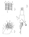
- Fig. 1 shows an example of an extruded strip not within the scope of the claims in perspective and in partial section and broken away;
- Fig. 2 shows a plan view of a flat wire core with low temperature threads knitted to the wire and which is suitable for use in the method of the present invention; and
- Fig. 3 is a schematic view illustrating a process.
- Now referring to Figure 1, an example of an extruded strip not within the scope of the claims is illustrated and indicated generally by the numeral 10. Extruded strip 10 is U-shaped in cross section with a pair of
legs 12 and 14 joined by aweb 16. Strip 10 comprises aU-shaped wire core 18 withelastomeric cover 20 extruded thereabout. Preferred material forelastomeric core 20 is selected from the group consisting of EPDM rubber, polyvinylchloride and thermoplastic rubber.Wire core 18 has transversely extendinglengths 22 bent into a generally U-shape and with lengths joined at opposite ends bybights 24.Elastomeric cover 20 has grippingribs 26 for secure retention of strip 10 onto a flange as is conventional in the art. Ahigh temperature thread 28 extends longitudinally throughcover 20 and is in bonding relationship therewith. - Now referring to Figure 2, a core used in the process for making strip 10 is illustrated. A conventional flat wire core is indicated generally by the
numeral 30 and is the type of core to be used as starting material in the process of the present invention.Wire core 30, with transversely extendinglengths 22 joined bybights 24, haslow temperature threads 34 extending longitudinally in the central portion thereof. Also, furtherlow temperature threads wire core 30 nearbights 24. Thelow temperature threads wire core 30 by knitting or other conventional means. The term "low temperature threads" is intended to mean that the threads, which are preferably made of a polymeric material such as polyester, have a melting point which is lower than the temperature to which they will be subjected in the extruder, i.e., the temperature at which the elastomeric material will have when extruded thereover. Suitable low temperature yarns may, for example, be polyester yarns which soften at a temperature between about 145 degrees Centegrade and about 160 degrees Centegrade and which melt at between about 160 degrees Centegrade and about 170 degrees Centegrade. It will be appreciated by those skilled in the art that the particular temperatures are dependent upon the temperatures of the extrudate and are functionally determined. - Now referring to Figure 3, the process is illustrated in somewhat schematic form with steps occurring as viewed from left to right. The step on the extreme right showing the high temperature thread woven through the
core 30 is incorrect, and not within the scope of the claim. First,wire core 30, is fed through formingrolls 40 which bendcore 30 into the desired U-shape as is conventional in the art. Then, now U-shapedwire core 30 is fed intoextruder 42. Elastomeric material, rubber is coextruded aboutcore 30 to form anelastomeric cover 20 in a generally conventional manner except that ahigh temperature thread 28 is also fed into the extruder just before theelastomeric material 44.High temperature thread 28 is positioned with respect tocore 30 in a selected manner to achieve the desired neutral bending axis. - In
extruder 42, thelow temperature threads core 30 in the longitudinal direction. However, whenelastomeric material 44 comes in contact with the threads they are heated thereby which results first in softening and then in melting of the threads.Threads transverse lengths 22 ofcore 30 would be free to move longitudinally. However, at least onehigh temperature thread 28 is fed into the extruder just before the elastomeric material. Suitablehigh temperature threads 28 are those threads which will not lose their strength at the processing temperatures encountered in the extrusion process. Suitablehigh temperature threads 28 may comprise polyamide or fiberglass material or metal. An adhesion coating may be used to enhance the bond between the high temperature thread and theelastomeric material 44.High temperature thread 28 is positioned with respect tocore 30 in selected fashion to provide the desired neutral bending axis of the final product. In Figure 1,high temperature thread 28 is positioned generally medially on leg 14. However,high temperature thread 28 can be selectively positioned to obtain a desired neutral bending axis and more than onethread 28 can be employed. For example, ahigh temperature thread 28 could be positioned alongweb 16 as well as along eitherleg 14 or 12.High temperature thread 28 further provides the tensile strength required to pull the strip through the extruder. - While a specific preferred embodiment of the present invention has been described above, it will be appreciated that the invention is subject to modification and variation and such modifications and variations are intended to be included within the fair scope of the following claims.
Claims (17)
- An extruded U-shaped strip (10) having a wire core (18) with transversely extending, parallel wire lengths (22) joined only at alternating ends with bights (24) in a continuous serpentine manner, said strip (10) having an elastomeric cover (20);
characterised in that said elastomeric cover (20) has (i) a selectively positioned high temperature thread (28) extending longitudinally therethrough to thereby select the neutral bending axis of said strip (10), and (ii) a low temperature (34) thread extending longitudinally and encapsulated in the elastomeric cover (20), the high temperature thread (28) being separate from the wire core and having a melting temperature higher than the melting temperature of the elastomeric cover (20) and the low temperature thread (34) having a melting temperature lower than the melting temperature of the elastomeric cover (20), whereby the low temperature thread (34) has melted during the extrusion of the strip (10). - The strip (10) of claim 1 wherein said high temperature thread (28) is positioned along one of the legs (12, 14) of the strip (10).
- The strip (10) of claim 13, wherein said low temperature thread (34) has a melting temperature of from about 160 degrees Centigrade to about 170 degrees Centigrade.
- The strip (10) of claim 3, wherein said high temperature thread (28) has a melting temperature of greater than 250 degrees Centigrade.
- The strip (10) of claim 4, wherein the elastomeric cover (20) comprises a material selected from the group consisting of EPDM rubber, polyvinylchloride and thermoplastic rubber.
- The strip (10) of claim 5 wherein said high temperature thread (28) comprises a polyamide material.
- The strip (10) of claim 6, wherein said high temperature thread (28) comprises a fiberglass material.
- The strip (10) of claim 7 wherein said high temperature thread (28) includes a bonding agent thereon.
- The strip (10) of claim 1, wherein said strip (10) carries a sealing bulb.
- The strip (10) of claim 1, wherein said strip (10) carries a lip.
- A method of making an extruded U-shaped strip (10) comprising the steps of:(A) feeding a wire core (30) to an extruder (42);(B) said core (30) having transversely extending, parallel wire lengths (22) joined only at alternating ends with bights (24) in a continuous serpentine manner, said wire lengths (22) joined in a longitudinal direction by low temperature threads (34);(C) coextruding an elastomeric material (44) about said wire core (30) in said extruder (42)(D) feeding a high temperature thread (28) separate from the wire core into said extruder (42) just upstream of said elastomeric material (44) and positioning said high temperature thread (28) to selectively determine the neutral bending axis of said strip (10); and(E) pulling said strip (10) from said extruder (42);said elastomeric material (44) having a temperature in said extruder (42) which is higher than the melting temperature of said low temperature threads (34) and lower than the melting temperature of said high temperature thread (28).
- The method of claim 11, wherein a plurality of high temperature threads (28) are fed into said extruder.
- The method of claim 12, wherein said elastomeric material (44) is EPDM and said high temperature thread (28) comprises polyester.
- The method of claim 13, wherein said elastomeric material (44) is EPDM and said high temperature thread (28) comprises fiberglass.
- The method of claim 14, wherein said high temperature thread (28) is positioned along a leg portion (12, 14) of said strip (10).
- The method of claim 15, wherein said high temperature thread (28) is positioned along the web portion (16) of said strip (10).
- The method of claim 16, wherein at least one said high temperature thread (28) is positioned along a leg (12, 14) of said strip (10) and at least one said high temperature thread (28) is positioned along the web (16) of said strip (10).
Applications Claiming Priority (2)
| Application Number | Priority Date | Filing Date | Title |
|---|---|---|---|
| US74296 | 1998-05-07 | ||
| US09/074,296 US6214267B1 (en) | 1998-05-07 | 1998-05-07 | Extrusion with variable neutral axis wire core |
Publications (4)
| Publication Number | Publication Date |
|---|---|
| EP0955148A1 EP0955148A1 (en) | 1999-11-10 |
| EP0955148B1 EP0955148B1 (en) | 2003-04-16 |
| EP0955148B2 true EP0955148B2 (en) | 2007-03-07 |
| EP0955148B9 EP0955148B9 (en) | 2007-06-13 |
Family
ID=22118824
Family Applications (1)
| Application Number | Title | Priority Date | Filing Date |
|---|---|---|---|
| EP99303465A Expired - Lifetime EP0955148B9 (en) | 1998-05-07 | 1999-05-04 | Extrusion with variable neutral axis wire core |
Country Status (10)
| Country | Link |
|---|---|
| US (1) | US6214267B1 (en) |
| EP (1) | EP0955148B9 (en) |
| JP (1) | JP2000061998A (en) |
| KR (1) | KR19990088063A (en) |
| AR (1) | AR015073A1 (en) |
| AT (1) | ATE237455T1 (en) |
| AU (1) | AU2693099A (en) |
| BR (1) | BR9901921A (en) |
| CA (1) | CA2270256A1 (en) |
| DE (1) | DE69906858T3 (en) |
Families Citing this family (10)
| Publication number | Priority date | Publication date | Assignee | Title |
|---|---|---|---|---|
| JP4161473B2 (en) * | 1999-07-01 | 2008-10-08 | 豊田合成株式会社 | Extruded product with insert and method for producing the same |
| US6461713B2 (en) * | 2000-12-18 | 2002-10-08 | Schlegel Corporation | Carrier with set down elongation reducing member |
| CN100417548C (en) * | 2004-04-07 | 2008-09-10 | 上海和达汽车配件有限公司 | Production of coating textile of vehicle door edging frame decorative strip |
| DE102005012685A1 (en) * | 2005-03-18 | 2006-09-21 | Metzeler Automotive Profile Systems Gmbh | Method of making continuous sealing profile for automobile use, includes main section extruded in one material and additional integral section extruded in second material |
| US7028510B1 (en) * | 2005-07-25 | 2006-04-18 | Nfa Corporation | Knitted wire carrier with locking stitch for weather seal backing |
| JP4672477B2 (en) * | 2005-07-26 | 2011-04-20 | 西川ゴム工業株式会社 | Manufacturing method of weather strip for automobile |
| DE102011076289A1 (en) * | 2011-05-23 | 2012-11-29 | SaarGummi technologies S.à.r.l. | Combined structure of extruded gasket and edge protection strand used in door of vehicle, has reinforcing insert that is arranged along longitudinal extension direction of strand element and is directly connected to strand element |
| DE102012000703A1 (en) * | 2012-01-16 | 2013-07-18 | Gm Global Technology Operations, Llc | sealing device |
| US10246803B2 (en) | 2015-09-14 | 2019-04-02 | Hope Global, Division Of Nfa Corp. | Knitted wire carrier for weather seal insert support with lockstitched reinforcing wire |
| CA3079904A1 (en) * | 2017-12-22 | 2019-06-27 | Rodexit Aps | Door seals with rodent resistant barrier; mounting and shielding strips for the mounting of such seals and for the protection of door leaves; mounting tools for mounting such doorseals and mounting and shielding strips; assemblies including such door seals; methods for rodent proofing_doors and protecting door leaves |
Family Cites Families (22)
| Publication number | Priority date | Publication date | Assignee | Title |
|---|---|---|---|---|
| US3124851A (en) | 1964-03-17 | Figure | ||
| US2574124A (en) | 1947-06-20 | 1951-11-06 | Schlegel Mfg Co | Weather strip |
| US3198689A (en) | 1962-01-29 | 1965-08-03 | Schlegel Mfg Co | Garnishing bead |
| GB1012759A (en) | 1963-09-09 | 1965-12-08 | Graham H G & Son Ltd | A protective moulding or beading which can form part of a draught excluding device |
| US4151237A (en) * | 1977-01-20 | 1979-04-24 | Lynenwerk Gmbh & Co. Kg | Production of cables with undulated tension relief elements |
| FR2626054B2 (en) * | 1979-03-30 | 1991-03-22 | Mesnel Sa Ets | PROFILE FOR SEALS, ESPECIALLY FOR AUTOMOTIVE BODYWORK |
| US4270792A (en) | 1979-12-05 | 1981-06-02 | General Motors Corporation | Molding assembly |
| US4343845A (en) | 1980-07-30 | 1982-08-10 | Schlegel Corporation | Elastomeric strip and method of manufacturing same |
| US4413033A (en) | 1982-06-07 | 1983-11-01 | Schlegel Corporation | Wire carrier and edge protector trim strip formed therefrom |
| US4934100A (en) * | 1983-12-13 | 1990-06-19 | Robert Adell | Wire insulated plastic edge guard |
| DE3405973A1 (en) * | 1984-02-18 | 1985-08-22 | Continental Gummi-Werke Ag, 3000 Hannover | METHOD FOR PRODUCING SEALING STRIPS AND SIMILAR PROFILE STRINGS FROM RUBBER AND RUBBER-LIKE ELASTOMERS |
| US4517233A (en) | 1984-03-16 | 1985-05-14 | Schlegel Corporation | Two-wire carrier edge protector trim strip |
| US4624093A (en) | 1984-04-12 | 1986-11-25 | Schlegel Corporation | Single-wire carrier edge protector trim strip |
| US5006291A (en) * | 1985-04-24 | 1991-04-09 | Plas/Steel Products, Inc. | Method for making fiber reinforced plastic tubing |
| US4963403A (en) * | 1987-10-30 | 1990-10-16 | Color Custom, Inc. | Unitary composite molding strip |
| JPH02293233A (en) * | 1989-04-21 | 1990-12-04 | Schlegel Uk Ltd | Supporter |
| US5009947A (en) | 1989-04-28 | 1991-04-23 | Schlegel Corporation | Elastomeric strip and method of manufacture |
| US5143666A (en) | 1989-04-28 | 1992-09-01 | Schlegel Corporation | Method for manufacturing an improved elastomeric strip |
| IE902223A1 (en) * | 1989-07-14 | 1991-01-16 | Schlegel Uk Holdings | Method of manufacturing an elastomeric strip |
| FR2686295B1 (en) * | 1992-01-21 | 1995-08-11 | Hutchinson | ELEMENT PROFILE ARME. |
| US5783125A (en) * | 1993-04-05 | 1998-07-21 | Crane Plastics Company Limited Partnership | Reinforced extrusion products and method of making same |
| US5416961A (en) | 1994-01-26 | 1995-05-23 | Schlegel Corporation | Knitted wire carrier having bonded warp threads and method for forming same |
-
1998
- 1998-05-07 US US09/074,296 patent/US6214267B1/en not_active Expired - Fee Related
-
1999
- 1999-04-27 CA CA002270256A patent/CA2270256A1/en not_active Abandoned
- 1999-05-04 DE DE69906858T patent/DE69906858T3/en not_active Expired - Lifetime
- 1999-05-04 EP EP99303465A patent/EP0955148B9/en not_active Expired - Lifetime
- 1999-05-04 AT AT99303465T patent/ATE237455T1/en not_active IP Right Cessation
- 1999-05-05 BR BR9901921-3A patent/BR9901921A/en not_active IP Right Cessation
- 1999-05-05 AU AU26930/99A patent/AU2693099A/en not_active Abandoned
- 1999-05-06 KR KR1019990016128A patent/KR19990088063A/en not_active Application Discontinuation
- 1999-05-06 AR ARP990102129A patent/AR015073A1/en unknown
- 1999-05-07 JP JP11126939A patent/JP2000061998A/en active Pending
Also Published As
| Publication number | Publication date |
|---|---|
| US6214267B1 (en) | 2001-04-10 |
| KR19990088063A (en) | 1999-12-27 |
| EP0955148B1 (en) | 2003-04-16 |
| ATE237455T1 (en) | 2003-05-15 |
| DE69906858D1 (en) | 2003-05-22 |
| DE69906858T3 (en) | 2007-10-11 |
| EP0955148A1 (en) | 1999-11-10 |
| EP0955148B9 (en) | 2007-06-13 |
| DE69906858T2 (en) | 2004-01-22 |
| JP2000061998A (en) | 2000-02-29 |
| AU2693099A (en) | 1999-11-18 |
| AR015073A1 (en) | 2001-04-11 |
| CA2270256A1 (en) | 1999-11-07 |
| BR9901921A (en) | 2001-01-09 |
Similar Documents
| Publication | Publication Date | Title |
|---|---|---|
| US4304816A (en) | Channel-shaped strip structures | |
| EP0045176B1 (en) | An elastomeric strip and method of manufacturing same | |
| US5009947A (en) | Elastomeric strip and method of manufacture | |
| US4676856A (en) | Weather strip for vehicle and producing method thereof | |
| US6787491B2 (en) | Woven composite fabric | |
| EP0955148B2 (en) | Extrusion with variable neutral axis wire core | |
| US5783312A (en) | Expanded metal strip for reinforcing a resilient product | |
| US4517233A (en) | Two-wire carrier edge protector trim strip | |
| EP0159136B1 (en) | Single-wire carrier edge protector trim strip | |
| US5143666A (en) | Method for manufacturing an improved elastomeric strip | |
| US5204157A (en) | Carrier and method | |
| JPH03157238A (en) | Combined molding and weather strip for vehicular application and its manufacture | |
| US6761954B2 (en) | Reinforced flexible laminate sealing strip and method of manufacturing same | |
| US20020102383A1 (en) | Carrier with set down elongation reducing member | |
| US6926787B2 (en) | Method of manufacturing a reinforced flexible laminate sealing strip | |
| GB2032500A (en) | Improvements in and Relating to Channel-shaped Strip Structures | |
| MXPA99004236A (en) | Wire nucleus extrusion with neu axle | |
| JPS61229636A (en) | Weather strip for car and its production | |
| JP2880944B2 (en) | Connection structure of reinforcing core | |
| EP0922598A1 (en) | Seal and/or trim components |
Legal Events
| Date | Code | Title | Description |
|---|---|---|---|
| PUAI | Public reference made under article 153(3) epc to a published international application that has entered the european phase |
Free format text: ORIGINAL CODE: 0009012 |
|
| AK | Designated contracting states |
Kind code of ref document: A1 Designated state(s): AT BE CH CY DE DK ES FI FR GB GR IE IT LI LU MC NL PT SE |
|
| AX | Request for extension of the european patent |
Free format text: AL;LT;LV;MK;RO;SI |
|
| 17P | Request for examination filed |
Effective date: 20000502 |
|
| AKX | Designation fees paid |
Free format text: AT BE CH CY DE DK ES FI FR GB GR IE IT LI LU MC NL PT SE |
|
| 17Q | First examination report despatched |
Effective date: 20011106 |
|
| GRAH | Despatch of communication of intention to grant a patent |
Free format text: ORIGINAL CODE: EPIDOS IGRA |
|
| GRAH | Despatch of communication of intention to grant a patent |
Free format text: ORIGINAL CODE: EPIDOS IGRA |
|
| GRAA | (expected) grant |
Free format text: ORIGINAL CODE: 0009210 |
|
| AK | Designated contracting states |
Designated state(s): AT BE CH CY DE DK ES FI FR GB GR IE IT LI LU MC NL PT SE |
|
| PG25 | Lapsed in a contracting state [announced via postgrant information from national office to epo] |
Ref country code: NL Free format text: LAPSE BECAUSE OF FAILURE TO SUBMIT A TRANSLATION OF THE DESCRIPTION OR TO PAY THE FEE WITHIN THE PRESCRIBED TIME-LIMIT Effective date: 20030416 Ref country code: LI Free format text: LAPSE BECAUSE OF FAILURE TO SUBMIT A TRANSLATION OF THE DESCRIPTION OR TO PAY THE FEE WITHIN THE PRESCRIBED TIME-LIMIT Effective date: 20030416 Ref country code: IT Free format text: LAPSE BECAUSE OF FAILURE TO SUBMIT A TRANSLATION OF THE DESCRIPTION OR TO PAY THE FEE WITHIN THE PRESCRIBED TIME-LIMIT;WARNING: LAPSES OF ITALIAN PATENTS WITH EFFECTIVE DATE BEFORE 2007 MAY HAVE OCCURRED AT ANY TIME BEFORE 2007. THE CORRECT EFFECTIVE DATE MAY BE DIFFERENT FROM THE ONE RECORDED. Effective date: 20030416 Ref country code: FI Free format text: LAPSE BECAUSE OF FAILURE TO SUBMIT A TRANSLATION OF THE DESCRIPTION OR TO PAY THE FEE WITHIN THE PRESCRIBED TIME-LIMIT Effective date: 20030416 Ref country code: CH Free format text: LAPSE BECAUSE OF FAILURE TO SUBMIT A TRANSLATION OF THE DESCRIPTION OR TO PAY THE FEE WITHIN THE PRESCRIBED TIME-LIMIT Effective date: 20030416 Ref country code: BE Free format text: LAPSE BECAUSE OF FAILURE TO SUBMIT A TRANSLATION OF THE DESCRIPTION OR TO PAY THE FEE WITHIN THE PRESCRIBED TIME-LIMIT Effective date: 20030416 Ref country code: AT Free format text: LAPSE BECAUSE OF FAILURE TO SUBMIT A TRANSLATION OF THE DESCRIPTION OR TO PAY THE FEE WITHIN THE PRESCRIBED TIME-LIMIT Effective date: 20030416 |
|
| REG | Reference to a national code |
Ref country code: GB Ref legal event code: FG4D |
|
| REG | Reference to a national code |
Ref country code: CH Ref legal event code: EP |
|
| PG25 | Lapsed in a contracting state [announced via postgrant information from national office to epo] |
Ref country code: LU Free format text: LAPSE BECAUSE OF NON-PAYMENT OF DUE FEES Effective date: 20030504 Ref country code: CY Free format text: LAPSE BECAUSE OF FAILURE TO SUBMIT A TRANSLATION OF THE DESCRIPTION OR TO PAY THE FEE WITHIN THE PRESCRIBED TIME-LIMIT Effective date: 20030504 |
|
| PG25 | Lapsed in a contracting state [announced via postgrant information from national office to epo] |
Ref country code: IE Free format text: LAPSE BECAUSE OF NON-PAYMENT OF DUE FEES Effective date: 20030505 |
|
| REF | Corresponds to: |
Ref document number: 69906858 Country of ref document: DE Date of ref document: 20030522 Kind code of ref document: P |
|
| REG | Reference to a national code |
Ref country code: IE Ref legal event code: FG4D |
|
| PG25 | Lapsed in a contracting state [announced via postgrant information from national office to epo] |
Ref country code: MC Free format text: LAPSE BECAUSE OF NON-PAYMENT OF DUE FEES Effective date: 20030531 |
|
| PG25 | Lapsed in a contracting state [announced via postgrant information from national office to epo] |
Ref country code: SE Free format text: LAPSE BECAUSE OF FAILURE TO SUBMIT A TRANSLATION OF THE DESCRIPTION OR TO PAY THE FEE WITHIN THE PRESCRIBED TIME-LIMIT Effective date: 20030716 Ref country code: PT Free format text: LAPSE BECAUSE OF FAILURE TO SUBMIT A TRANSLATION OF THE DESCRIPTION OR TO PAY THE FEE WITHIN THE PRESCRIBED TIME-LIMIT Effective date: 20030716 Ref country code: GR Free format text: LAPSE BECAUSE OF FAILURE TO SUBMIT A TRANSLATION OF THE DESCRIPTION OR TO PAY THE FEE WITHIN THE PRESCRIBED TIME-LIMIT Effective date: 20030716 Ref country code: DK Free format text: LAPSE BECAUSE OF FAILURE TO SUBMIT A TRANSLATION OF THE DESCRIPTION OR TO PAY THE FEE WITHIN THE PRESCRIBED TIME-LIMIT Effective date: 20030716 |
|
| NLV1 | Nl: lapsed or annulled due to failure to fulfill the requirements of art. 29p and 29m of the patents act | ||
| PG25 | Lapsed in a contracting state [announced via postgrant information from national office to epo] |
Ref country code: ES Free format text: LAPSE BECAUSE OF FAILURE TO SUBMIT A TRANSLATION OF THE DESCRIPTION OR TO PAY THE FEE WITHIN THE PRESCRIBED TIME-LIMIT Effective date: 20031030 |
|
| REG | Reference to a national code |
Ref country code: CH Ref legal event code: PL |
|
| PLBQ | Unpublished change to opponent data |
Free format text: ORIGINAL CODE: EPIDOS OPPO |
|
| PLBI | Opposition filed |
Free format text: ORIGINAL CODE: 0009260 |
|
| PLAX | Notice of opposition and request to file observation + time limit sent |
Free format text: ORIGINAL CODE: EPIDOSNOBS2 |
|
| ET | Fr: translation filed | ||
| REG | Reference to a national code |
Ref country code: IE Ref legal event code: MM4A |
|
| 26 | Opposition filed |
Opponent name: METZELER AUTOMOTIVE PROFILE SYSTEMS GMBH Effective date: 20040115 |
|
| PLAX | Notice of opposition and request to file observation + time limit sent |
Free format text: ORIGINAL CODE: EPIDOSNOBS2 |
|
| PLBB | Reply of patent proprietor to notice(s) of opposition received |
Free format text: ORIGINAL CODE: EPIDOSNOBS3 |
|
| REG | Reference to a national code |
Ref country code: FR Ref legal event code: CD |
|
| PUAH | Patent maintained in amended form |
Free format text: ORIGINAL CODE: 0009272 |
|
| STAA | Information on the status of an ep patent application or granted ep patent |
Free format text: STATUS: PATENT MAINTAINED AS AMENDED |
|
| 27A | Patent maintained in amended form |
Effective date: 20070307 |
|
| AK | Designated contracting states |
Kind code of ref document: B2 Designated state(s): AT BE CH CY DE DK ES FI FR GB GR IE IT LI LU MC NL PT SE |
|
| REG | Reference to a national code |
Ref country code: ES Ref legal event code: FD2A Effective date: 20030505 |
|
| ET3 | Fr: translation filed ** decision concerning opposition | ||
| PGFP | Annual fee paid to national office [announced via postgrant information from national office to epo] |
Ref country code: GB Payment date: 20100507 Year of fee payment: 12 |
|
| GBPC | Gb: european patent ceased through non-payment of renewal fee |
Effective date: 20110504 |
|
| PG25 | Lapsed in a contracting state [announced via postgrant information from national office to epo] |
Ref country code: GB Free format text: LAPSE BECAUSE OF NON-PAYMENT OF DUE FEES Effective date: 20110504 |
|
| PGFP | Annual fee paid to national office [announced via postgrant information from national office to epo] |
Ref country code: DE Payment date: 20130531 Year of fee payment: 15 |
|
| PGFP | Annual fee paid to national office [announced via postgrant information from national office to epo] |
Ref country code: FR Payment date: 20130531 Year of fee payment: 15 |
|
| REG | Reference to a national code |
Ref country code: DE Ref legal event code: R119 Ref document number: 69906858 Country of ref document: DE |
|
| REG | Reference to a national code |
Ref country code: DE Ref legal event code: R119 Ref document number: 69906858 Country of ref document: DE Effective date: 20141202 |
|
| REG | Reference to a national code |
Ref country code: FR Ref legal event code: ST Effective date: 20150130 |
|
| PG25 | Lapsed in a contracting state [announced via postgrant information from national office to epo] |
Ref country code: DE Free format text: LAPSE BECAUSE OF NON-PAYMENT OF DUE FEES Effective date: 20141202 |
|
| PG25 | Lapsed in a contracting state [announced via postgrant information from national office to epo] |
Ref country code: FR Free format text: LAPSE BECAUSE OF NON-PAYMENT OF DUE FEES Effective date: 20140602 |