JP4161473B2 - Extruded product with insert and method for producing the same - Google Patents
Extruded product with insert and method for producing the same Download PDFInfo
- Publication number
- JP4161473B2 JP4161473B2 JP18736399A JP18736399A JP4161473B2 JP 4161473 B2 JP4161473 B2 JP 4161473B2 JP 18736399 A JP18736399 A JP 18736399A JP 18736399 A JP18736399 A JP 18736399A JP 4161473 B2 JP4161473 B2 JP 4161473B2
- Authority
- JP
- Japan
- Prior art keywords
- insert
- gap
- foam
- die
- resin
- Prior art date
- Legal status (The legal status is an assumption and is not a legal conclusion. Google has not performed a legal analysis and makes no representation as to the accuracy of the status listed.)
- Expired - Fee Related
Links
Images


Classifications
-
- B—PERFORMING OPERATIONS; TRANSPORTING
- B32—LAYERED PRODUCTS
- B32B—LAYERED PRODUCTS, i.e. PRODUCTS BUILT-UP OF STRATA OF FLAT OR NON-FLAT, e.g. CELLULAR OR HONEYCOMB, FORM
- B32B27/00—Layered products comprising a layer of synthetic resin
- B32B27/06—Layered products comprising a layer of synthetic resin as the main or only constituent of a layer, which is next to another layer of the same or of a different material
- B32B27/065—Layered products comprising a layer of synthetic resin as the main or only constituent of a layer, which is next to another layer of the same or of a different material of foam
-
- B—PERFORMING OPERATIONS; TRANSPORTING
- B32—LAYERED PRODUCTS
- B32B—LAYERED PRODUCTS, i.e. PRODUCTS BUILT-UP OF STRATA OF FLAT OR NON-FLAT, e.g. CELLULAR OR HONEYCOMB, FORM
- B32B27/00—Layered products comprising a layer of synthetic resin
- B32B27/06—Layered products comprising a layer of synthetic resin as the main or only constituent of a layer, which is next to another layer of the same or of a different material
- B32B27/08—Layered products comprising a layer of synthetic resin as the main or only constituent of a layer, which is next to another layer of the same or of a different material of synthetic resin
-
- B—PERFORMING OPERATIONS; TRANSPORTING
- B32—LAYERED PRODUCTS
- B32B—LAYERED PRODUCTS, i.e. PRODUCTS BUILT-UP OF STRATA OF FLAT OR NON-FLAT, e.g. CELLULAR OR HONEYCOMB, FORM
- B32B27/00—Layered products comprising a layer of synthetic resin
- B32B27/30—Layered products comprising a layer of synthetic resin comprising vinyl (co)polymers; comprising acrylic (co)polymers
- B32B27/304—Layered products comprising a layer of synthetic resin comprising vinyl (co)polymers; comprising acrylic (co)polymers comprising vinyl halide (co)polymers, e.g. PVC, PVDC, PVF, PVDF
-
- B—PERFORMING OPERATIONS; TRANSPORTING
- B32—LAYERED PRODUCTS
- B32B—LAYERED PRODUCTS, i.e. PRODUCTS BUILT-UP OF STRATA OF FLAT OR NON-FLAT, e.g. CELLULAR OR HONEYCOMB, FORM
- B32B27/00—Layered products comprising a layer of synthetic resin
- B32B27/32—Layered products comprising a layer of synthetic resin comprising polyolefins
-
- B—PERFORMING OPERATIONS; TRANSPORTING
- B32—LAYERED PRODUCTS
- B32B—LAYERED PRODUCTS, i.e. PRODUCTS BUILT-UP OF STRATA OF FLAT OR NON-FLAT, e.g. CELLULAR OR HONEYCOMB, FORM
- B32B2266/00—Composition of foam
- B32B2266/02—Organic
- B32B2266/0214—Materials belonging to B32B27/00
- B32B2266/0221—Vinyl resin
- B32B2266/0235—Vinyl halide, e.g. PVC, PVDC, PVF, PVDF
-
- B—PERFORMING OPERATIONS; TRANSPORTING
- B32—LAYERED PRODUCTS
- B32B—LAYERED PRODUCTS, i.e. PRODUCTS BUILT-UP OF STRATA OF FLAT OR NON-FLAT, e.g. CELLULAR OR HONEYCOMB, FORM
- B32B2266/00—Composition of foam
- B32B2266/02—Organic
- B32B2266/0214—Materials belonging to B32B27/00
- B32B2266/025—Polyolefin
-
- B—PERFORMING OPERATIONS; TRANSPORTING
- B32—LAYERED PRODUCTS
- B32B—LAYERED PRODUCTS, i.e. PRODUCTS BUILT-UP OF STRATA OF FLAT OR NON-FLAT, e.g. CELLULAR OR HONEYCOMB, FORM
- B32B2327/00—Polyvinylhalogenides
- B32B2327/06—PVC, i.e. polyvinylchloride
-
- B—PERFORMING OPERATIONS; TRANSPORTING
- B32—LAYERED PRODUCTS
- B32B—LAYERED PRODUCTS, i.e. PRODUCTS BUILT-UP OF STRATA OF FLAT OR NON-FLAT, e.g. CELLULAR OR HONEYCOMB, FORM
- B32B2605/00—Vehicles
- B32B2605/08—Cars
-
- Y—GENERAL TAGGING OF NEW TECHNOLOGICAL DEVELOPMENTS; GENERAL TAGGING OF CROSS-SECTIONAL TECHNOLOGIES SPANNING OVER SEVERAL SECTIONS OF THE IPC; TECHNICAL SUBJECTS COVERED BY FORMER USPC CROSS-REFERENCE ART COLLECTIONS [XRACs] AND DIGESTS
- Y10—TECHNICAL SUBJECTS COVERED BY FORMER USPC
- Y10T—TECHNICAL SUBJECTS COVERED BY FORMER US CLASSIFICATION
- Y10T428/00—Stock material or miscellaneous articles
- Y10T428/249921—Web or sheet containing structurally defined element or component
- Y10T428/249953—Composite having voids in a component [e.g., porous, cellular, etc.]
Description
【0001】
【発明の属する技術分野】
本発明は、自動車のオープニングトリムなど、補強部と空間部とが長手方向に交互に形成された硬質のインサートをもつ押出成形品とその製造方法に関する。
【0002】
【従来の技術】
自動車のオープニングトリムは、図5に示すように、断面略U字形状で長尺状の基部100と、基部100内に埋設されたインサート2とから構成されている。基部100は軟質ポリ塩化ビニル(PVC)あるいは熱可塑性オレフィン(TPO)などの軟質樹脂から形成され、その互いに対向する内側表面には、それぞれリップ部101が互いに対向するように突出形成されている。またインサート1は、図2に示すようにU字形状の補強部10と、複数の補強部10をそれぞれ間隔を隔てて順に連結する橋部11とから構成され、これにより隣接する補強部10どうしの間にはそれぞれ間隙部12が形成されている。そして補強部10で基部100のU字形状を保持するとともに、橋部11及び間隙部12の存在により、基部100は曲げ変形可能とされている。
【0003】
したがって、このように構成されたオープニングトリムを車両に組み付ける場合には、一対のリップ部101の間に被取付部を挟むようにして組み付ける。これにより被取付部は一対のリップ部101によって挟持され、補強部10の存在する部分で保持強度が確保される。そして間隙部12の存在する部分で曲げ変形させることで、被取付部の形状に確実に沿わせて組み付けることが可能となっている。
【0004】
このオープニングトリムは、インサート2を供給しながらその周囲に基部100を構成する溶融樹脂を供給して押し出す押出成形によって製造されている。
【0005】
【発明が解決しようとする課題】
ところが従来のオープニングトリムにおいては、補強部10の存在する部分と間隙部12の存在する部分で基部100の表面が凹凸となり、見映え及び触感が悪いという不具合があった。
【0006】
本発明はこのような事情に鑑みてなされたものであり、補強部と間隙部とをもつ硬質のインサートによって補強された押出成形品の、表面形状を平滑として外観品質を向上させることを目的とする。
【0007】
【課題を解決するための手段】
上記課題を解決する本発明のインサートをもつ押出成形品の特徴は、少なくとも一部に間隙部をもつように配置され間隙部の部位で曲げ変形可能な硬質のインサートと、インサートを埋設し間隙部を充填する熱可塑性樹脂製の発泡体層と、発泡体層の表面を被覆する熱可塑性樹脂製の表皮層とよりなり、発泡体層はインサートの表面に当接する部分における発泡倍率(b)が間隙部を充填する部分における発泡倍率(a)より小さく、a≧b+0.15の関係を満たし、発泡倍率(a)は1.2〜6.0の範囲にあり発泡倍率(b)は1.05〜5.0の範囲にあることにある。
【0008】
またこの押出成形品を製造する本発明の製造方法の特徴は、少なくとも一部に間隙部をもつ硬質のインサートと発泡樹脂と表皮用樹脂とを同時に押し出して、インサートとインサートを埋設する熱可塑性樹脂製の発泡体層と発泡体層の表面を被覆する熱可塑性樹脂製の表皮層とからなる押出成形品を製造する方法であって、
インサートの表面に発泡樹脂を供給する第1ダイと、第1ダイより押出方向で下流側に配置され発泡樹脂の表面に表皮用樹脂を供給するとともにインサート、発泡体層、表皮層からなる積層体を押出成形する第2ダイと、を備えた押出成形装置を用い、発泡樹脂はインサートが第2ダイに入る前に第1ダイ内である程度発泡して第2ダイ内で発泡がほぼ完了し、発泡樹脂が発泡する際にインサートの表面に対向する部分の発泡容積が間隙部を充填する部分の発泡容積より小さくなるように表皮層側から規制しながら押出成形し、表皮層の表面を平滑とすることにある。
【0009】
【発明の実施の形態】
押出成形の場合には、押出速度が一定であれば成形材料の単位時間当たりの供給量も一定となる。ところが従来のオープニングトリムにおいては、補強部10の位置でも間隙部12の位置でも基部の断面積は同一であるので、間隙部12の位置では補強部10が存在しない分だけ成形材料が厚肉となる。そのため成形後の成形材料の体積収縮量は間隙部12の位置の方が補強部10の位置より大きくなり、押出成形直後の表面は平滑であっても冷却後には間隙部12の位置で凹状となり補強部10の位置で凸状となって、見映え及び触感が悪いという不具合が生じている。
【0010】
そこで本発明の押出成形品の製造方法では、発泡樹脂が発泡する際にインサートの表面に対向する部分の発泡容積が間隙部を充填する部分の発泡容積より小さくなるように表皮層側から規制しながら押出成形している。こうすることにより、発泡樹脂の発泡倍率は、インサートの表面に対向する部分では低くなり、間隙部を充填する部分では高くなる。したがって成形後の冷却による体積収縮量の差と発泡による体積膨張量の差が相殺され、表皮層の表面を平滑にすることができる。
【0011】
そして本発明の押出成形品では、発泡体層はインサートの表面に当接する部分における発泡倍率が間隙部を充填する部分における発泡倍率より小さいので、成形後の冷却による体積収縮量の差と発泡による体積膨張量の差が相殺され、従来に比べて表皮層の表面が平滑となる。したがって外観品質が向上し、見映え及び触感が向上する。
【0012】
インサートは樹脂あるいは金属などから形成された硬質のものであり、少なくとも一部に間隙部をもつようにされる。この間隙部の存在により、押出成形品は曲げ変形可能となる。間隙部は複数のインサートの間で構成してもよいし、例えば網状あるいは梯子状のインサートなどインサート自体に間隙部を形成することもできる。
【0013】
発泡体層は、発泡TPO、発泡PVCなどから形成することができる。この発泡体層は、インサートの表面に当接する部分における発泡倍率が間隙部を充填する部分における発泡倍率より小さくなっている。押出成形においては、押出金型で表面形状を規制することができるので、インサート表面と金型型面との間隔を所定値に設定しておくことにより、インサートの表面と間隙部とで発泡体層の発泡倍率を所定範囲に容易に調節することができる。
【0014】
表皮層は、軟質PVCあるいはTPOなどから形成することができる。表皮層の表面は、シボあるいは植毛などを施すことによって外観品質をさらに向上させることができる。発泡体層によって表面の凹凸が低減されているので、表皮層の厚さは全体にほぼ均一とすることができ、押出成形にて容易に形成することができる。
【0015】
本発明の押出成形品を製造するには、押出金型内へインサートを供給しながら、発泡樹脂と表皮層用樹脂とをこの順でその表面に押し出し、押出金型内で発泡樹脂を発泡させて発泡体層を形成する。そして本発明では、押出金型の型面とインサートとの間における発泡容積は、間隙部における発泡容積より小さくなるように構成されている。したがってインサートの表面に当接する部分における発泡倍率は、間隙部を充填する部分における発泡倍率より小さくなり、インサートの表面に当接する部分の方が小さく、間隙部を充填する部分の方が大きく膨張しようとする。
【0016】
そしてこの押出成形品が押出金型から出て冷却されると、発泡体層及び表皮層は共に収縮する。成形材料の体積の差によって収縮量が異なり、インサートの表面に当接する部分における収縮量が小さく、間隙部を充填する部分における収縮量が大きくなる。したがって発泡による体積膨張量と冷却による体積収縮量とが相殺され、結果的に発泡体層の表面は凹凸が少ない平滑な表面となる。また表皮層の体積収縮量はどの部分もほぼ同等であるので、得られる押出成形品の表面は凹凸の少ない平滑な表面とすることができる。
【0017】
得られる押出成形品において、インサートが存在する部分における発泡樹脂の発泡倍率は1.05〜5.0の範囲が望ましく、間隙部における発泡樹脂の発泡倍率は1.2〜6.0の範囲が望ましい。両発泡倍率がそれぞれの下限より小さいと得られる発泡成形品の表面の凹凸が目立つようになり、それぞれの上限を超えても表面の凹凸が目立つようになる。そして間隙部における発泡樹脂の発泡倍率aは、インサートが存在する部分における発泡樹脂の発泡倍率bに対してa>bであればよいが、次式の関係を満たすことがさらに望ましい。次式の関係を満たすことで、得られる発泡成形品の表面を一層平滑とすることができる。
【0018】
a≧b+0.15
なお本発明の押出成形品の形状は、インサートの全面を発泡体層及び表皮層で被覆された構造としてもよいし、一表面にインサートの一表面が表出しその反対側表面に発泡体層と表皮層とが積層された構造とすることもできる。また発泡体層の発泡を主として押出金型内で行うこと以外は、押出成形方法には特に制限がなく、従来と同様に行うことができる。
【0019】
【実施例】
以下、実施例と従来例及び試験例により本発明を具体的に説明する。
【0020】
(実施例)
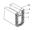
図1に本発明の一実施例で製造されたオープニングトリムの要部拡大図を示す。このオープニングトリムは、インサート1と、インサート1が埋設された発泡体層2と、発泡体層2の表面に被覆された表皮層3とからなり、断面略U字形状の一定形状をなしている。そして表皮層3には、内側の両表面から突出して互いに対向する一対のリップ部30が長手方向に延びて形成されている。
【0021】
インサート1は板金から形成され、図2に示すように略U字形状の複数の補強部10が長手方向にそれぞれ間隔を隔てて列設され、隣接する補強部10はそれぞれ橋部11によって接続されている。これにより隣接する補強部10どうしの間には、それぞれ間隙部12が形成されている。そして橋部11は変形可能であり、また間隙部12の存在により、インサート1は曲げ変形可能となっている。
【0022】
図3に本実施例に用いた押出成形装置の先端部分の断面図を示し、この押出成形装置を用いた本実施例の押出成形品の製造方法を以下に説明する。
【0023】
押出成形装置は、主孔40をもつ第1ダイ4と、第1ダイ4の先端に固定された第2ダイ5とからなり、主孔40内にトーピード6が進退するように構成されている。第1ダイ4には、主孔40の後端に開口し発泡TPO7を供給する第1供給通路41が設けられている。また第1通路41の前方には第1ダイ4の前端及び第2ダイ5の後端に開口しTPO8を供給する第2供給通路42が設けられている。そしてトーピード6の中心には、トーピード6の前端に開口しインサート1を供給する第3供給通路60が形成されている。
【0024】
そしてこの製造方法では、第3供給通路60から主孔40内にインサート1を供給するとともに、第1供給通路41から発泡TPO7を供給し、その表面にさらに第2供給通路42からTPO8を供給しながら押出成形を行う。このようにして積層された3層の積層体は、第2ダイ5の断面略U字形状の開口50から出て所定速度で引き取られる。発泡TPO7は主孔40内である程度発泡し、第2ダイ5内で発泡がほぼ完了するが、第2ダイ5から出た後もある程度発泡するように構成されている。
【0025】
ここで第2ダイ5内における発泡TPO7の厚さ方向の発泡は、図4に示すようにインサート1の補強部10の位置では第2ダイ5の一方の型面とインサート1とで規制され、間隙部12の位置では第2ダイ5の両側の型面で規制される。したがって補強部10の位置における発泡容積は間隙部12の位置における発泡容積より小さくなり、補強部10の位置における発泡倍率は間隙部12の位置における発泡倍率より小さくなる。
【0026】
本実施例では、インサート1の肉厚は0.4mmであり、発泡体層2の肉厚は2.0mmであって、補強部10の位置における発泡倍率が1.5、間隙部12の位置における発泡倍率が3.0となるように構成されている。なお表皮層3の肉厚は1.0mmであり、そのHS硬度は65である。
【0027】
(従来例)
第1供給通路41から供給される材料を第2供給通路42から供給されるTPOと同じ材料とし、発泡体層2を中実層としたこと以外は実施例と同様にして押出成形品を製造した。
【0028】
<試験・評価>
得られたそれぞれのオープニングトリムの表面の凹凸を測定したところ、実施例品の凹部と凸部の高低差は5〜30μmであり、従来例品の高低差である50〜150μmと比べて格段に平滑化されて高い外観品質を有していた。これは発泡体層2を形成し、しかも補強部10の位置と間隙部12の位置における発泡倍率を異ならせた効果であることが明らかである。
【0029】
(試験例)
インサート1に種々の肉厚のものを用い、補強部10の位置の発泡倍率と間隙部12の位置の発泡倍率を表1に示すように種々変化させたこと以外は実施例と同様にして、種々の押出成形品を製造した。それぞれの押出成形品の表面の凹凸を測定し、凹凸差が30μm以下のものを○、30〜50μmのものを△、50μm以上のものを×として結果を表1に示す。なお表1において、補強部10の位置の発泡倍率と間隙部12の位置の発泡倍率が同一のものは、成形品が第2ダイ5を出てから規制がない状態で自然発泡させたものである。
【0030】
表1より、補強部10の位置の発泡倍率bと間隙部12の位置の発泡倍率aとの関係がa≦bでは表面の凹凸差が大きく、発泡倍率が低い範囲では特に凹凸差が大きいことがわかる。そしてa≧b+0.15の範囲が特に好ましいことがわかる。
【0031】
なお両発泡倍率の差が大きい範囲であれば凹凸差は小さいが、表1の右上部分のように間隙部12の位置の発泡倍率aと補強部10の位置の発泡倍率bとの差があまり大きくなると、逆に間隙部12の部分が凸となり補強部10の部分が凹となって凹凸が目立つようになるので好ましくない。
【0032】
【表1】

【発明の効果】
すなわち本発明のインサートをもつ押出成形品の製造方法によれば、表面が平滑で外観品質及び触感に優れた押出成形品を容易かつ確実に製造することができる。そして本発明のインサートをもつ押出成形品によれば、表面が平滑であるために外観品質及び触感に優れ、オープニングトリムなどに適用すれば自動車の意匠性及び高級感が向上する。
【図面の簡単な説明】
【図1】本発明の一実施例の押出成形品の一部断面で示す斜視図である。
【図2】本発明の一実施例の押出成形品に用いたインサートの要部斜視図である。
【図3】本発明の一実施例の押出成形品の製造方法に用いた押出成形装置の要部断面図である。
【図4】本発明の一実施例の押出成形品の製造方法に用いた押出成形装置内における押出成形品の要部断面図である。
【図5】従来の押出成形品の一部断面で示す斜視図である。
【符号の説明】
1:インサート 2:発泡体層 3:表皮層
10:補強部 11:橋部 12:間隙部[0001]
BACKGROUND OF THE INVENTION
The present invention relates to an extruded product having a hard insert in which reinforcing portions and space portions are alternately formed in the longitudinal direction, such as an opening trim of an automobile, and a manufacturing method thereof.
[0002]
[Prior art]
As shown in FIG. 5, the opening trim of an automobile includes a long base 100 having a substantially U-shaped cross section and an
[0003]
Therefore, when the opening trim configured as described above is assembled to the vehicle, the opening trim is assembled with the attached portion sandwiched between the pair of
[0004]
This opening trim is manufactured by extrusion molding in which the molten resin constituting the base portion 100 is supplied and extruded while the
[0005]
[Problems to be solved by the invention]
However, the conventional opening trim has a problem that the surface of the base portion 100 is uneven at the portion where the reinforcing
[0006]
The present invention has been made in view of such circumstances, and an object thereof is to improve the appearance quality by smoothing the surface shape of an extruded product reinforced by a hard insert having a reinforcing portion and a gap portion. To do.
[0007]
[Means for Solving the Problems]
The feature of the extrusion-molded article having the insert of the present invention that solves the above-mentioned problems is that a hard insert that is arranged so as to have a gap at least partially and can be bent and deformed at a position of the gap, and the gap is formed by embedding the insert. A foam layer made of a thermoplastic resin that fills the surface of the foam and a skin layer made of a thermoplastic resin that covers the surface of the foam layer, and the foam layer has an expansion ratio (b) at a portion that contacts the surface of the insert. The expansion ratio (a) is smaller than the expansion ratio (a) in the portion filling the gap, satisfies the relationship of a ≧ b + 0.15 , the expansion ratio (a) is in the range of 1.2 to 6.0, and the expansion ratio (b) is 1. It exists in the range of 05-5.0 .
[0008]
The manufacturing method of the present invention for manufacturing the extruded product is characterized in that a thermoplastic resin in which the insert and the insert are embedded by simultaneously extruding a hard insert having a gap in at least a part, a foamed resin and a skin resin. A method for producing an extruded product comprising a foam layer made of a thermoplastic resin and a skin layer made of a thermoplastic resin covering the surface of the foam layer,
A first die for supplying foamed resin to the surface of the insert, and a laminate comprising an insert, a foam layer, and a skin layer while being disposed downstream of the first die in the extrusion direction and supplying the resin for the skin to the surface of the foamed resin A foaming resin is foamed to some extent in the first die before the insert enters the second die, and the foaming is almost completed in the second die. When foaming resin is foamed, extrusion molding is performed while regulating from the skin layer side so that the foaming volume of the part facing the surface of the insert is smaller than the foaming volume of the part filling the gap, and the surface of the skin layer is made smooth There is to do.
[0009]
DETAILED DESCRIPTION OF THE INVENTION
In the case of extrusion molding, if the extrusion speed is constant, the supply amount of the molding material per unit time is also constant. However, in the conventional opening trim, the cross-sectional area of the base is the same at both the position of the reinforcing
[0010]
Therefore, in the method for producing an extruded product of the present invention, when the foamed resin is foamed, the foam layer is restricted from the skin layer side so that the foam volume of the portion facing the surface of the insert is smaller than the foam volume of the portion filling the gap. While extruding. By doing so, the foaming ratio of the foamed resin is low at the portion facing the surface of the insert, and is high at the portion filling the gap. Therefore, the difference in volume shrinkage due to cooling after molding and the difference in volume expansion due to foaming are offset, and the surface of the skin layer can be smoothed.
[0011]
In the extruded product of the present invention, the foam layer has a lower foaming ratio in the part contacting the surface of the insert than the foaming ratio in the part filling the gap. The difference in volume expansion amount is canceled out, and the surface of the skin layer becomes smoother than in the conventional case. Accordingly, the appearance quality is improved, and the appearance and tactile feel are improved.
[0012]
The insert is made of a hard material made of resin or metal, and has a gap at least partially. Due to the presence of the gap, the extruded product can be bent and deformed. The gap may be formed between a plurality of inserts, or the gap may be formed in the insert itself such as a net-like or ladder-like insert.
[0013]
The foam layer can be formed from foamed TPO, foamed PVC, or the like. In the foam layer, the expansion ratio in the portion that abuts on the surface of the insert is smaller than the expansion ratio in the portion that fills the gap. In extrusion molding, the surface shape can be regulated by an extrusion mold, so by setting the distance between the insert surface and the mold surface to a predetermined value, the foam is formed between the insert surface and the gap portion. The expansion ratio of the layer can be easily adjusted to a predetermined range.
[0014]
The skin layer can be formed from soft PVC or TPO. The surface quality of the skin layer can be further improved by applying texture or flocking. Since the unevenness of the surface is reduced by the foam layer, the thickness of the skin layer can be made substantially uniform throughout and can be easily formed by extrusion.
[0015]
In order to produce the extruded product of the present invention, while supplying the insert into the extrusion mold, the foamed resin and the skin layer resin are extruded in this order on the surface, and the foamed resin is foamed in the extrusion mold. To form a foam layer. In the present invention, the foam volume between the mold surface of the extrusion mold and the insert is configured to be smaller than the foam volume in the gap. Therefore, the expansion ratio in the portion that contacts the surface of the insert is smaller than the expansion ratio in the portion that fills the gap, the portion that contacts the surface of the insert is smaller, and the portion that fills the gap expands more greatly. And
[0016]
And when this extruded product comes out of the extrusion mold and is cooled, both the foam layer and the skin layer shrink. The amount of shrinkage varies depending on the volume difference of the molding material, the amount of shrinkage at the portion in contact with the surface of the insert is small, and the amount of shrinkage at the portion filling the gap is large. Therefore, the volume expansion amount due to foaming and the volume shrinkage amount due to cooling are offset, and as a result, the surface of the foam layer becomes a smooth surface with few irregularities. In addition, since the volume shrinkage of the skin layer is almost the same in all parts, the surface of the obtained extrusion-molded product can be a smooth surface with few irregularities.
[0017]
In the obtained extruded product, the expansion ratio of the foamed resin in the portion where the insert is present is preferably in the range of 1.05 to 5.0, and the expansion ratio of the foamed resin in the gap is in the range of 1.2 to 6.0. desirable. When both the foaming ratios are smaller than the respective lower limits, the surface irregularities of the obtained foamed molded product become conspicuous, and even when the respective upper limits are exceeded, the surface irregularities become conspicuous. The foaming ratio a of the foamed resin in the gap may be a> b with respect to the foaming ratio b of the foamed resin in the portion where the insert exists, but it is more desirable to satisfy the relationship of the following formula. By satisfy | filling the relationship of following Formula, the surface of the foam-molded article obtained can be smoothed further.
[0018]
a ≧ b + 0.15
The shape of the extruded product of the present invention may be a structure in which the entire surface of the insert is covered with a foam layer and a skin layer, or one surface of the insert is exposed on one surface and the foam layer on the opposite surface. It can also be set as the structure where the skin layer was laminated | stacked. Moreover, there is no restriction | limiting in particular in an extrusion method except performing foaming of a foam layer mainly in an extrusion die, It can carry out similarly to the past.
[0019]
【Example】
Hereinafter, the present invention will be specifically described with reference to examples, conventional examples, and test examples.
[0020]
(Example)
FIG. 1 shows an enlarged view of a main part of an opening trim manufactured in one embodiment of the present invention. The opening trim includes an
[0021]
The
[0022]
FIG. 3 shows a cross-sectional view of the tip portion of the extrusion molding apparatus used in this embodiment, and a method for manufacturing an extrusion molded article of this embodiment using this extrusion molding apparatus will be described below.
[0023]
The extrusion molding apparatus includes a
[0024]
In this manufacturing method, the
[0025]
Here, foaming in the thickness direction of the foamed
[0026]
In the present embodiment, the thickness of the
[0027]
(Conventional example)
Extruded product is manufactured in the same manner as in Example except that the material supplied from the
[0028]
<Test and evaluation>
When the unevenness of the surface of each of the obtained opening trims was measured, the height difference between the concave portion and the convex portion of the example product was 5 to 30 μm, which is markedly higher than the height difference of 50 to 150 μm of the conventional product. It was smooth and had high appearance quality. This is clearly the effect of forming the
[0029]
(Test example)
Using inserts of various thicknesses, the same as in the embodiment, except that the expansion ratio at the position of the reinforcing
[0030]
From Table 1, the relationship between the expansion ratio b at the position of the reinforcing
[0031]
If the difference between the two expansion ratios is large, the unevenness difference is small, but the difference between the expansion ratio a at the position of the
[0032]
[Table 1]
【The invention's effect】
That is, according to the method for producing an extruded product having the insert of the present invention, an extruded product having a smooth surface and excellent appearance quality and touch can be produced easily and reliably. And according to the extrusion molded product having the insert of the present invention, the surface is smooth, so that it has excellent appearance quality and touch, and when applied to an opening trim, the design and quality of an automobile are improved.
[Brief description of the drawings]
FIG. 1 is a perspective view showing a partial cross section of an extruded product according to an embodiment of the present invention.
FIG. 2 is a perspective view of an essential part of an insert used for an extruded product according to an embodiment of the present invention.
FIG. 3 is a cross-sectional view of an essential part of an extrusion molding apparatus used in a method for producing an extrusion molded product according to an embodiment of the present invention.
FIG. 4 is a cross-sectional view of an essential part of the extrusion molded product in the extrusion molding apparatus used in the method of manufacturing an extrusion molded product according to one embodiment of the present invention.
FIG. 5 is a perspective view showing a partial cross section of a conventional extruded product.
[Explanation of symbols]
1: Insert 2: Foam layer 3: Skin layer
10: Reinforcement part 11: Bridge part 12: Gap part
Claims (3)
該インサートの表面に該発泡樹脂を供給する第1ダイと、該第1ダイより押出方向で下流側に配置され該発泡樹脂の表面に該表皮用樹脂を供給するとともに該インサート、該発泡体層、該表皮層からなる積層体を押出成形する第2ダイと、を備えた押出成形装置を用い、 A first die for supplying the foamed resin to the surface of the insert; and an insert and the foam layer that are disposed downstream of the first die in the extrusion direction and supply the skin resin to the surface of the foamed resin A second die for extruding the laminate comprising the skin layer, and an extrusion molding apparatus comprising:
該発泡樹脂は該インサートが該第2ダイに入る前に該第1ダイ内である程度発泡して該第2ダイ内で発泡がほぼ完了し、The foamed resin foams to some extent in the first die before the insert enters the second die, and the foaming is almost completed in the second die;
該発泡樹脂が発泡する際に該インサートの表面に対向する部分の発泡容積が該間隙部を充填する部分の発泡容積より小さくなるように該表皮層側から規制しながら押出成形し、該表皮層の表面を平滑とすることを特徴とするインサートをもつ押出成形品の製造方法。Extruding while regulating from the skin layer side so that the foam volume of the portion facing the surface of the insert is smaller than the foam volume of the portion filling the gap when the foamed resin is foamed, and the skin layer A method for producing an extrusion-molded article having an insert characterized in that the surface of the molded article is smooth.
少なくとも一部に間隙部をもつように配置され該間隙部の部位で曲げ変形可能な硬質のインサートと、該インサートを埋設し該間隙部を充填する熱可塑性樹脂製の発泡体層と、該発泡体層の表面を被覆する熱可塑性樹脂製の表皮層とよりなり、該発泡体層は該インサートの表面に当接する部分における発泡倍率(b)が該間隙部を充填する部分における発泡倍率(a)より小さく、a≧b+0.15の関係を満たし、該発泡倍率(a)は1.2〜6.0の範囲にあり該発泡倍率(b)は1.05〜5.0の範囲にあることを特徴とするインサートをもつ押出成形品。A hard insert that is arranged so as to have a gap at least partially and can be bent and deformed at a portion of the gap, a foam layer made of a thermoplastic resin that embeds the insert and fills the gap, and the foam A foam layer made of a thermoplastic resin covering the surface of the body layer, and the foam layer has a foaming ratio (b) in a part contacting the surface of the insert, and a foaming ratio (a) in a part filling the gap ) Smaller, satisfying the relationship of a ≧ b + 0.15, the expansion ratio (a) is in the range of 1.2 to 6.0, and the expansion ratio (b) is in the range of 1.05 to 5.0. Extrusion product with an insert characterized by this.
Priority Applications (2)
| Application Number | Priority Date | Filing Date | Title |
|---|---|---|---|
| JP18736399A JP4161473B2 (en) | 1999-07-01 | 1999-07-01 | Extruded product with insert and method for producing the same |
| US10/154,969 US6676865B2 (en) | 1999-07-01 | 2002-05-28 | Extrusion molding provided with insert and method of producing the same |
Applications Claiming Priority (1)
| Application Number | Priority Date | Filing Date | Title |
|---|---|---|---|
| JP18736399A JP4161473B2 (en) | 1999-07-01 | 1999-07-01 | Extruded product with insert and method for producing the same |
Publications (3)
| Publication Number | Publication Date |
|---|---|
| JP2001009889A JP2001009889A (en) | 2001-01-16 |
| JP2001009889A5 JP2001009889A5 (en) | 2007-10-04 |
| JP4161473B2 true JP4161473B2 (en) | 2008-10-08 |
Family
ID=16204695
Family Applications (1)
| Application Number | Title | Priority Date | Filing Date |
|---|---|---|---|
| JP18736399A Expired - Fee Related JP4161473B2 (en) | 1999-07-01 | 1999-07-01 | Extruded product with insert and method for producing the same |
Country Status (2)
| Country | Link |
|---|---|
| US (1) | US6676865B2 (en) |
| JP (1) | JP4161473B2 (en) |
Families Citing this family (12)
| Publication number | Priority date | Publication date | Assignee | Title |
|---|---|---|---|---|
| EP1568090B1 (en) * | 2002-12-02 | 2010-10-13 | Bathium Canada Inc. | Co-extrusion manufacturing process of thin film electrochemical cell for lithium polymer batteries |
| JP4223446B2 (en) | 2003-10-06 | 2009-02-12 | 西川ゴム工業株式会社 | Automotive weatherstrip |
| WO2008111331A1 (en) | 2007-03-14 | 2008-09-18 | Tokai Kogyo Co., Ltd. | Trim member, core member thereof, process for producing them, and apparatus therefor |
| JP5105913B2 (en) * | 2007-03-14 | 2012-12-26 | 東海興業株式会社 | Trim core material, core material manufacturing method, and core material manufacturing apparatus |
| JP2008254533A (en) * | 2007-04-03 | 2008-10-23 | Tokai Kogyo Co Ltd | Trim material and manufacturing method for the same |
| JP2008265068A (en) * | 2007-04-18 | 2008-11-06 | Tokai Kogyo Co Ltd | Manufacturing method and manufacturing equipment for trim material |
| US20100015456A1 (en) | 2008-07-16 | 2010-01-21 | Eastman Chemical Company | Thermoplastic formulations for enhanced paintability toughness and melt process ability |
| US8734909B2 (en) * | 2010-03-10 | 2014-05-27 | Eastman Chemical Company | Methods and apparatus for coating substrates |
| US8865261B2 (en) | 2012-12-06 | 2014-10-21 | Eastman Chemical Company | Extrusion coating of elongated substrates |
| US9340232B2 (en) | 2013-05-03 | 2016-05-17 | Tesla Motors, Inc. | Extrusion piece with insert of dissimilar material |
| US9920526B2 (en) | 2013-10-18 | 2018-03-20 | Eastman Chemical Company | Coated structural members having improved resistance to cracking |
| US9744707B2 (en) | 2013-10-18 | 2017-08-29 | Eastman Chemical Company | Extrusion-coated structural members having extruded profile members |
Family Cites Families (19)
| Publication number | Priority date | Publication date | Assignee | Title |
|---|---|---|---|---|
| US3367851A (en) * | 1964-04-09 | 1968-02-06 | Minnesota Mining & Mfg | Non-woven conductive paper mat |
| US3960601A (en) * | 1974-09-27 | 1976-06-01 | Union Carbide Corporation | Fuel cell electrode |
| DE3012007A1 (en) | 1980-03-28 | 1981-10-08 | Gebr. Happich Gmbh, 5600 Wuppertal | FOAM BODY, IN PARTICULAR DASHBOARD FOR MOTOR VEHICLES |
| US4505797A (en) * | 1983-03-24 | 1985-03-19 | Ionics, Incorporated | Ion-exchange membranes reinforced with non-woven carbon fibers |
| US5649982A (en) * | 1987-05-21 | 1997-07-22 | Yardney Technical Products, Inc. | Process for manufacturing super capacitor |
| GB8827180D0 (en) * | 1988-11-21 | 1988-12-29 | Schlegel Uk Holdings | Composite extrusion |
| US5474841A (en) | 1992-04-23 | 1995-12-12 | Kanegafuchi Kagaku Kogyo Kabushiki Kaisha | Polypropylene resin cellular molded article having a skin and production method therefor |
| GB9223781D0 (en) * | 1992-11-13 | 1993-01-06 | Woodhams Raymond T | Cellulose reinforced oriented thermoplastic composites |
| US5945048A (en) * | 1995-03-25 | 1999-08-31 | Ensinger; Wilfried | Process and device for extruding polymer melts to form hollow chamber sections |
| DE19517911A1 (en) * | 1995-05-16 | 1996-11-21 | Sgl Technik Gmbh | Process for converting multi-dimensional sheet-like structures consisting of polyacrylonitrile fibers into the thermally stabilized state |
| US5651217A (en) | 1996-01-25 | 1997-07-29 | The Standard Products Company | Flexible glass run with rigid molded support |
| US6497919B1 (en) * | 1996-04-17 | 2002-12-24 | Industrial Thermo Polymers Limited | Two-part coated foam structure |
| AU719275B2 (en) * | 1996-11-21 | 2000-05-04 | Marley Mouldings Inc. | Weatherstrip product formed by sequential extrusion of cellular and non-cellular plastic resins |
| AU739888B2 (en) * | 1997-09-10 | 2001-10-25 | Wella Aktiengesellschaft | Method of producing foamed plastics-material hollow bodies |
| US6214267B1 (en) * | 1998-05-07 | 2001-04-10 | The Standard Products Company | Extrusion with variable neutral axis wire core |
| CA2287114A1 (en) * | 1998-11-23 | 2000-05-23 | Kenneth W. Rood | Motor vehicle seal assembly and method of manufacture |
| US6189198B1 (en) * | 1999-08-26 | 2001-02-20 | Kingston-Warren Corporation | Method of making a vanishing warp carrier seal |
| US6601802B1 (en) * | 1999-12-30 | 2003-08-05 | Lsp Products Group Inc | Method for making extruded acoustic pipe support |
| US6514604B2 (en) * | 2001-02-02 | 2003-02-04 | Schlegel Corporation | Migration inhibiting layer for a weatherstrip |
-
1999
- 1999-07-01 JP JP18736399A patent/JP4161473B2/en not_active Expired - Fee Related
-
2002
- 2002-05-28 US US10/154,969 patent/US6676865B2/en not_active Expired - Fee Related
Also Published As
| Publication number | Publication date |
|---|---|
| JP2001009889A (en) | 2001-01-16 |
| US20020192451A1 (en) | 2002-12-19 |
| US6676865B2 (en) | 2004-01-13 |
Similar Documents
| Publication | Publication Date | Title |
|---|---|---|
| JP4161473B2 (en) | Extruded product with insert and method for producing the same | |
| EP1566302B1 (en) | Extruded product | |
| KR0170081B1 (en) | Method for molding laminated assembly | |
| EP1741543A1 (en) | Interior finishing panel for vehicle and method of manufacturing the same | |
| US20050072052A1 (en) | Weather strip for automobile | |
| US5419863A (en) | Method of making a seamless backfilled molding | |
| US20080315621A1 (en) | Trim Panel for the Interior of a Motor Vehicle and a Manufacturing Process for Such a Trim Panel | |
| JP2001009889A5 (en) | ||
| JP2001038796A (en) | Blow molded article and blow molding method | |
| JP2004142716A (en) | Extrusion-molded article for automobile and its manufacturing method | |
| JP2003040042A (en) | Vehicular roof molding | |
| JP3343955B2 (en) | Extrusion method of cored trim | |
| JPH0216920Y2 (en) | ||
| JP3128047B2 (en) | Laminate molded product and its manufacturing device | |
| JP4482326B2 (en) | Interior parts for vehicles | |
| US7226106B2 (en) | Molding and method of manufacturing the same | |
| JP5259208B2 (en) | Vehicle interior panel and method of forming the same | |
| JP5405868B2 (en) | Glass run and method for producing the same | |
| JP2006103234A (en) | Manufacturing method of vehicle interior trim member with foamed skin | |
| JP2004231163A (en) | Vehicular extrusion molding | |
| JP2580890B2 (en) | Patterned connection method for extruded bodies with different stiffness | |
| JP2005305917A (en) | Expansion molded part and its manufacturing method | |
| JP3050509B2 (en) | Molding apparatus and molding method for two-color laminated molded article | |
| JP3326938B2 (en) | Long decorative material and manufacturing method | |
| JP4697590B2 (en) | Molding method for extrusion molding of synthetic resin core material |
Legal Events
| Date | Code | Title | Description |
|---|---|---|---|
| A621 | Written request for application examination |
Free format text: JAPANESE INTERMEDIATE CODE: A621 Effective date: 20060228 |
|
| A521 | Request for written amendment filed |
Free format text: JAPANESE INTERMEDIATE CODE: A523 Effective date: 20070822 |
|
| A977 | Report on retrieval |
Free format text: JAPANESE INTERMEDIATE CODE: A971007 Effective date: 20071128 |
|
| A131 | Notification of reasons for refusal |
Free format text: JAPANESE INTERMEDIATE CODE: A131 Effective date: 20071204 |
|
| A521 | Request for written amendment filed |
Free format text: JAPANESE INTERMEDIATE CODE: A523 Effective date: 20080118 |
|
| A521 | Request for written amendment filed |
Free format text: JAPANESE INTERMEDIATE CODE: A523 Effective date: 20080129 |
|
| A131 | Notification of reasons for refusal |
Free format text: JAPANESE INTERMEDIATE CODE: A131 Effective date: 20080304 |
|
| A521 | Request for written amendment filed |
Free format text: JAPANESE INTERMEDIATE CODE: A523 Effective date: 20080417 |
|
| A131 | Notification of reasons for refusal |
Free format text: JAPANESE INTERMEDIATE CODE: A131 Effective date: 20080515 |
|
| A521 | Request for written amendment filed |
Free format text: JAPANESE INTERMEDIATE CODE: A523 Effective date: 20080609 |
|
| TRDD | Decision of grant or rejection written | ||
| A01 | Written decision to grant a patent or to grant a registration (utility model) |
Free format text: JAPANESE INTERMEDIATE CODE: A01 Effective date: 20080701 |
|
| A01 | Written decision to grant a patent or to grant a registration (utility model) |
Free format text: JAPANESE INTERMEDIATE CODE: A01 |
|
| A61 | First payment of annual fees (during grant procedure) |
Free format text: JAPANESE INTERMEDIATE CODE: A61 Effective date: 20080714 |
|
| FPAY | Renewal fee payment (event date is renewal date of database) |
Free format text: PAYMENT UNTIL: 20110801 Year of fee payment: 3 |
|
| R150 | Certificate of patent or registration of utility model |
Free format text: JAPANESE INTERMEDIATE CODE: R150 |
|
| FPAY | Renewal fee payment (event date is renewal date of database) |
Free format text: PAYMENT UNTIL: 20110801 Year of fee payment: 3 |
|
| FPAY | Renewal fee payment (event date is renewal date of database) |
Free format text: PAYMENT UNTIL: 20120801 Year of fee payment: 4 |
|
| FPAY | Renewal fee payment (event date is renewal date of database) |
Free format text: PAYMENT UNTIL: 20130801 Year of fee payment: 5 |
|
| LAPS | Cancellation because of no payment of annual fees |