EP0954397B1 - Process and tool for manufacturing flat bearing shells - Google Patents
Process and tool for manufacturing flat bearing shells Download PDFInfo
- Publication number
- EP0954397B1 EP0954397B1 EP98906884A EP98906884A EP0954397B1 EP 0954397 B1 EP0954397 B1 EP 0954397B1 EP 98906884 A EP98906884 A EP 98906884A EP 98906884 A EP98906884 A EP 98906884A EP 0954397 B1 EP0954397 B1 EP 0954397B1
- Authority
- EP
- European Patent Office
- Prior art keywords
- bearing shell
- tool
- pressing
- strip material
- bearing
- Prior art date
- Legal status (The legal status is an assumption and is not a legal conclusion. Google has not performed a legal analysis and makes no representation as to the accuracy of the status listed.)
- Expired - Lifetime
Links
- 238000000034 method Methods 0.000 title claims abstract description 39
- 238000004519 manufacturing process Methods 0.000 title claims abstract description 8
- 239000000463 material Substances 0.000 claims abstract description 31
- 238000003825 pressing Methods 0.000 claims description 46
- 238000004080 punching Methods 0.000 claims description 17
- 238000005520 cutting process Methods 0.000 claims description 15
- 230000007704 transition Effects 0.000 claims description 12
- 238000005452 bending Methods 0.000 claims description 10
- 230000000295 complement effect Effects 0.000 claims description 5
- 238000003801 milling Methods 0.000 claims description 3
- 238000010008 shearing Methods 0.000 claims 2
- 238000000748 compression moulding Methods 0.000 abstract 2
- 239000011257 shell material Substances 0.000 description 90
- 210000001331 nose Anatomy 0.000 description 13
- 238000005192 partition Methods 0.000 description 7
- 238000012545 processing Methods 0.000 description 5
- 238000003754 machining Methods 0.000 description 4
- 239000002699 waste material Substances 0.000 description 4
- 238000011161 development Methods 0.000 description 3
- 238000013461 design Methods 0.000 description 2
- 238000000926 separation method Methods 0.000 description 2
- 230000015572 biosynthetic process Effects 0.000 description 1
- 238000005422 blasting Methods 0.000 description 1
- 230000006835 compression Effects 0.000 description 1
- 238000007906 compression Methods 0.000 description 1
- 230000006378 damage Effects 0.000 description 1
- 230000000694 effects Effects 0.000 description 1
- 238000005516 engineering process Methods 0.000 description 1
- 239000008384 inner phase Substances 0.000 description 1
- 230000002028 premature Effects 0.000 description 1
- 238000010079 rubber tapping Methods 0.000 description 1
- 238000003860 storage Methods 0.000 description 1
- 238000012549 training Methods 0.000 description 1
Images

Classifications
-
- F—MECHANICAL ENGINEERING; LIGHTING; HEATING; WEAPONS; BLASTING
- F16—ENGINEERING ELEMENTS AND UNITS; GENERAL MEASURES FOR PRODUCING AND MAINTAINING EFFECTIVE FUNCTIONING OF MACHINES OR INSTALLATIONS; THERMAL INSULATION IN GENERAL
- F16C—SHAFTS; FLEXIBLE SHAFTS; ELEMENTS OR CRANKSHAFT MECHANISMS; ROTARY BODIES OTHER THAN GEARING ELEMENTS; BEARINGS
- F16C33/00—Parts of bearings; Special methods for making bearings or parts thereof
- F16C33/02—Parts of sliding-contact bearings
- F16C33/04—Brasses; Bushes; Linings
- F16C33/06—Sliding surface mainly made of metal
- F16C33/14—Special methods of manufacture; Running-in
-
- B—PERFORMING OPERATIONS; TRANSPORTING
- B23—MACHINE TOOLS; METAL-WORKING NOT OTHERWISE PROVIDED FOR
- B23P—METAL-WORKING NOT OTHERWISE PROVIDED FOR; COMBINED OPERATIONS; UNIVERSAL MACHINE TOOLS
- B23P15/00—Making specific metal objects by operations not covered by a single other subclass or a group in this subclass
- B23P15/003—Making specific metal objects by operations not covered by a single other subclass or a group in this subclass bearings
-
- F—MECHANICAL ENGINEERING; LIGHTING; HEATING; WEAPONS; BLASTING
- F16—ENGINEERING ELEMENTS AND UNITS; GENERAL MEASURES FOR PRODUCING AND MAINTAINING EFFECTIVE FUNCTIONING OF MACHINES OR INSTALLATIONS; THERMAL INSULATION IN GENERAL
- F16C—SHAFTS; FLEXIBLE SHAFTS; ELEMENTS OR CRANKSHAFT MECHANISMS; ROTARY BODIES OTHER THAN GEARING ELEMENTS; BEARINGS
- F16C17/00—Sliding-contact bearings for exclusively rotary movement
- F16C17/02—Sliding-contact bearings for exclusively rotary movement for radial load only
-
- F—MECHANICAL ENGINEERING; LIGHTING; HEATING; WEAPONS; BLASTING
- F16—ENGINEERING ELEMENTS AND UNITS; GENERAL MEASURES FOR PRODUCING AND MAINTAINING EFFECTIVE FUNCTIONING OF MACHINES OR INSTALLATIONS; THERMAL INSULATION IN GENERAL
- F16C—SHAFTS; FLEXIBLE SHAFTS; ELEMENTS OR CRANKSHAFT MECHANISMS; ROTARY BODIES OTHER THAN GEARING ELEMENTS; BEARINGS
- F16C9/00—Bearings for crankshafts or connecting-rods; Attachment of connecting-rods
- F16C9/04—Connecting-rod bearings; Attachments thereof
-
- F—MECHANICAL ENGINEERING; LIGHTING; HEATING; WEAPONS; BLASTING
- F16—ENGINEERING ELEMENTS AND UNITS; GENERAL MEASURES FOR PRODUCING AND MAINTAINING EFFECTIVE FUNCTIONING OF MACHINES OR INSTALLATIONS; THERMAL INSULATION IN GENERAL
- F16C—SHAFTS; FLEXIBLE SHAFTS; ELEMENTS OR CRANKSHAFT MECHANISMS; ROTARY BODIES OTHER THAN GEARING ELEMENTS; BEARINGS
- F16C2220/00—Shaping
- F16C2220/60—Shaping by removing material, e.g. machining
- F16C2220/66—Shaping by removing material, e.g. machining by milling
-
- F—MECHANICAL ENGINEERING; LIGHTING; HEATING; WEAPONS; BLASTING
- F16—ENGINEERING ELEMENTS AND UNITS; GENERAL MEASURES FOR PRODUCING AND MAINTAINING EFFECTIVE FUNCTIONING OF MACHINES OR INSTALLATIONS; THERMAL INSULATION IN GENERAL
- F16C—SHAFTS; FLEXIBLE SHAFTS; ELEMENTS OR CRANKSHAFT MECHANISMS; ROTARY BODIES OTHER THAN GEARING ELEMENTS; BEARINGS
- F16C2220/00—Shaping
- F16C2220/80—Shaping by separating parts, e.g. by severing, cracking
- F16C2220/82—Shaping by separating parts, e.g. by severing, cracking by cutting
-
- F—MECHANICAL ENGINEERING; LIGHTING; HEATING; WEAPONS; BLASTING
- F16—ENGINEERING ELEMENTS AND UNITS; GENERAL MEASURES FOR PRODUCING AND MAINTAINING EFFECTIVE FUNCTIONING OF MACHINES OR INSTALLATIONS; THERMAL INSULATION IN GENERAL
- F16C—SHAFTS; FLEXIBLE SHAFTS; ELEMENTS OR CRANKSHAFT MECHANISMS; ROTARY BODIES OTHER THAN GEARING ELEMENTS; BEARINGS
- F16C2220/00—Shaping
- F16C2220/80—Shaping by separating parts, e.g. by severing, cracking
- F16C2220/84—Shaping by separating parts, e.g. by severing, cracking by perforating; by punching; by stamping-out
-
- F—MECHANICAL ENGINEERING; LIGHTING; HEATING; WEAPONS; BLASTING
- F16—ENGINEERING ELEMENTS AND UNITS; GENERAL MEASURES FOR PRODUCING AND MAINTAINING EFFECTIVE FUNCTIONING OF MACHINES OR INSTALLATIONS; THERMAL INSULATION IN GENERAL
- F16C—SHAFTS; FLEXIBLE SHAFTS; ELEMENTS OR CRANKSHAFT MECHANISMS; ROTARY BODIES OTHER THAN GEARING ELEMENTS; BEARINGS
- F16C2223/00—Surface treatments; Hardening; Coating
- F16C2223/02—Mechanical treatment, e.g. finishing
- F16C2223/04—Mechanical treatment, e.g. finishing by sizing, by shaping to final size by small plastic deformation, e.g. by calibrating or coining
Definitions
- the invention relates to a method and a tool according to the preamble of claim 1 or claim 10
- Manufacture of flat bearing shells one of Band material bearing shell sections are separated, these sections are bent essentially semicircular, if necessary, the transition areas from the parting surfaces chamfered to the inside facing the sliding partner as well as outside and inside and the parting surfaces of the so formed bearing shell are calibrated.
- US-A-5 199 170 The closest prior art is US-A-5 199 170.
- Calibrating the outside of the bearing shell Circumferential length and the calibration of the parting surfaces takes place so far by clearing the dividing surfaces.
- the parting surfaces are machined so that the Desired circumferential length on the outside of the bearing shell is achieved. For this, a facility for machining required.
- Calibrating the Inside of the bearing shell is usually done just before the final dimension of the finished bearing shell is checked by a broach towards the Rotation axis of the later sliding partner on the inside the bearing shell is moved past.
- the present invention is therefore based on the object is based on a method of the type mentioned at the beginning to improve that the calibration of the Outside and the parting surfaces of the flat bearing shells simpler in terms of process technology and inexpensive is feasible than has been the case so far.
- the tool to be used for this points to Compression of the dividing surfaces or the transition area from the separating surfaces to the inside of the bearing shells and lowerable press bridge, which the bearing shell from Interface to interface spanned and only for Development of the transition area from the parting surfaces to The inside of the bearing shell engages in it.
- the semi-circular pre-bent bearing shell sections during of the pressing process at their limit the storage width End faces supported in the press workpiece. So there will be support stops within the press tool brought the mentioned end faces, directly before or at the same time as the press bridge is lowered against the parting surfaces of the bearing shell, so that during the Pressing process does not increase the width of the bearing shell becomes.
- a radial nose in a pressing process Notch of the press tool released serves the bearing shells within a bearing keep immovable or non-rotatable and are in themselves known. However, they are usually in a separate one Process step punched out or notched.
- the shell is released after the Nose by pressing or tapping on the nose opposite separating surface within the Pressing tool rotated that they from the recess of the Press tool is released and after opening the Longitudinal pressing tool, i.e. in the direction of rotation a later sliding partner of the bearing shell from the Press tool can be pushed out.
- a later sliding partner of the bearing shell from the Press tool can be pushed out.
- the separation of the bearing shell sections from the strip material is preferably carried out in such a way that Shear off on the lower side of the Band material no over the bottom, i.e. the later Outside of the bearing shell, protruding ridge formed becomes.
- a punching tool is used used, the lower knife towards the Stamp has cutting edges striving upwards.
- the present invention also has the object underlying a tool for performing the To provide the inventive method.
- the pressing tool in the circumferential length of the Calibrate the bearing shell and the separating surfaces, whereby at the same time the respective inner chamfer in the transition area the dividing surfaces to the inside of the bearing shell in is shaped as desired.
- the pressing tool according to the invention is advantageously characterized by a preliminary stage with a semicircular bending punch for bending the from Band material separated bearing shell sections Semicircle shape
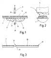
- Figures 1 to 3 show the process of separating one Bearing shell section of the band material and a related used punching tool.
- the reference number 2 is a from a roll of tape, not shown, continuously developed 2-component tape material called, by that by means of the punch 4 bearing shell sections are continuously separated.
- the punching tool 4 comprises an upper knife Stamp 6 and two lower blades 8, 10, between them the punch 6 to separate one Bearing shell section is passed.
- the Punch 6 is complementary to the cross-sectional contour of the Tape material 2 on the punch 6 facing Side trained. Before the tape is cut in Bearing shell sections is fed to the punching tool, will face the future sliding partner Top 12 an oil groove 14 extending in the longitudinal direction, introduced by milling, blasting or broaching.
- the oil groove 14 has a flat and parallel to the top extending groove bottom 16 and inclined to the top 12 extending groove flanks 18.
- the Stamp 6 thus has a complementary to Cross-sectional contour of the oil groove 14 formed projection 20 on.
- the two lower knives 8, 10 each have a transverse to the longitudinal or transport direction of the strip material 2 extending Cutting edge 22 or 24 on. These cutting edges 22, 24 are striving towards the punch 6 upwards educated.
- the punch 2 is down driven and between the cutting edges 22, 24 of the Lower knife 8, 10 moved through, so that when cutting the bearing shell section 26 a the width of the Stamp stamp corresponding waste piece 28 is generated.
- each Bearing shell section 26 is in the direction of movement Stamp 6 pulled down.
- 10 is achieved that none of the Top side 12 of the respective bearing shell section 26 opposite bottom 34 protruding cutting burr is formed, which would have to be removed or itself when inserting the bearing shell into a bearing can have a disastrous effect.
- the Stamp 6 is the waste piece 28 early sheared off, so that a formed in this case too Cutting burr does not protrude beyond the bottom 34.
- the Bearing shell sections 26 substantially semicircular bent. This takes place in a not shown Pre-bending stage shown in Figures 4 to 6 Press tool 40 instead. After bending to semicircular shape the bearing shell sections 26 in the in the figures 4 and 5 shown working position of the pressing tool preferably moved, in which the outside as well the dividing surfaces of the semicircular curved Bearing shell sections 26 are calibrated.
- the pressing tool 40 comprises a basic receiving body 42, which one of the outer shape of the bearing shell to be produced corresponding die 44 for the Bearing shell sections 26 carries.
- a hint Press upper part 46 shown is a press bridge 48 in Can be raised and lowered with respect to the die 44.
- the lower one End position is over to the base body 42 abutting stop blocks 50 defined or set.
- the press bridge 48 points against separating surfaces 52 Bearing shell sections 26 press bearing surfaces 54 that can be created on.
- the press bearing surfaces 54 go into one in the Bearing shell 26 engaging material guide section 56.
- the exact shape of the press bearing surfaces 54 in Transition area to the material guide section 56 corresponds the inner phase to be produced in the transition from the Partitions 52 to the inside 58 of the bearing shell 26.
- the respective Feed slope 66 is ramped outward current projection 74 of the tool flanks 60, 62 is formed, whose vertically returning ramp flank 76 is an axial one Stop surface 76 for the side tool flanks 60, 68 forms when closing the pressing tool.
- the axial Stop surface 76 partially abuts against it indicated depth stop 78, the base body is to be assigned.
- FIG. 8 On the left side of the press bridge 48 in FIG additional pressing tool stamp 80 is provided, which over the press bearing surface 54 in the form of a wedge-shaped Pressing or punching projection 82 protrudes.
- the Press tool stamp 80 or the wedge-shaped projection 82 serve to notch one shown in Figure 6 radial nose 84.
- a bearing shell section 26 is from the pre-bending stage to that in FIGS. 4 and 5 Machining position of the pressing tool 40 shown postponed.
- the upper press part 46 is in the direction lowered on the die 44. This strikes first the axial stop surface 76 against the depth stop 78 and thereby limits the movement of the side Tool flanks 60, 62 (see Figure 5).
- the upper press part 46 slides the adjusting means 68 via the respective delivery slope 66 of the side Tool flanks 60, 62 and move them across Lift direction towards each other until they reach the side Flanks 70, 72 of the bearing shell 26 with their contact section 86 and thus the width of the manufactured Define bearing shell.
- the final fixing of the width of the bearing shell 26 sets the press bridge 48 with its two press bearing surfaces 54 on the two separating surfaces 52 of the bearing shell 26 and compresses these separating surfaces 52 or the bearing shell 26.
- the outer side 88 of the bearing shell 26 Circumferential length calibrated and at the same time Partitions 52 brought to their final shape without that further parting surface processing, for example, by broaching the parting surfaces becomes necessary.
- the movement of the Press bridge 48 is countered by abutting the stops 50 the basic receiving body 42 of the pressing tool 40 stopped.
- the bearing shell 26 now has its final circumferential length on.
- the bearing shell material is used 26 displaced in the circumferential direction of the bearing shell. That this is not done in an uncontrolled manner by the Material guide section in the transition area of the Press bearing surfaces 54 to the inside of the bearing shell achieved and in that during the upsetting of the Partitions 52 the side tool flanks 60, 62 the Support bearing shell 26 and the ultimately desired Define bearing shell width precisely.
- the radial nose 84 When calibrating the outside 88 or the separating surfaces 52 through the upsetting process described above furthermore by the wedge-shaped punching projection 82 of the additional press die 80 the radial nose 84 into a radial recess 90 provided for this purpose notched in the die 44. If the radial nose 84 in this preferred way when calibrating the outside 88 and the separating surfaces 52 of the bearing shell 26, This means that the notched nose can be milled from the inside to be dispensed with, as this shape is already at Notching can be formed by the pressing tool.
Landscapes
- Engineering & Computer Science (AREA)
- General Engineering & Computer Science (AREA)
- Mechanical Engineering (AREA)
- Sliding-Contact Bearings (AREA)
- Forging (AREA)
- Polishing Bodies And Polishing Tools (AREA)
Abstract
Description
Die Erfindung betrifft ein Verfahren sowie ein Werkzeug nach dem Oberbegriff von Anspruch 1 bzw. Anspruch 10 zum Herstellen von Flachlagerschalen, wobei von einem Bandmaterial Lagerschalenabschnitte abgetrennt werden, diese Abschnitte im wesentlichen halbkreisförmig gebogen, gegebenenfalls die Übergangsbereiche von den Trennflächen zu der dem Gleitpartner zugewandten Innenseite angefast sowie Außen- und Innenseite und die Trennflächen der so gebildeten Lagerschale kalibriert werden. Nächsthommender Stand der Technik ist US-A-5 199 170.The invention relates to a method and a tool according to the preamble of claim 1 or claim 10 Manufacture of flat bearing shells, one of Band material bearing shell sections are separated, these sections are bent essentially semicircular, if necessary, the transition areas from the parting surfaces chamfered to the inside facing the sliding partner as well as outside and inside and the parting surfaces of the so formed bearing shell are calibrated. The closest prior art is US-A-5 199 170.
Das Kalibrieren der Außenseite der Lagerschale auf Umfangslänge und das Kalibrieren der Trennflächen erfolgt bislang durch Räumen der Trennflächen. Die Trennflächen werden also derart spanabhebend bearbeitet, dass die erwünschte Umfangslänge auf der Außenseite der Lagerschale erreicht wird. Hierfür wird eine Einrichtung für spanabhebende Bearbeitung benötigt. Das Kalibrieren der Innenseite der Lagerschale erfolgt üblicherweise kurz bevor die schlussendliche Abmessung der fertigen Lagerschale geprüft wird, indem eine Räumnadel in Richtung der Rotationsachse des späteren Gleitpartners an der Innenseite der Lagerschale vorbeibewegt wird.Calibrating the outside of the bearing shell Circumferential length and the calibration of the parting surfaces takes place so far by clearing the dividing surfaces. The parting surfaces are machined so that the Desired circumferential length on the outside of the bearing shell is achieved. For this, a facility for machining required. Calibrating the Inside of the bearing shell is usually done just before the final dimension of the finished bearing shell is checked by a broach towards the Rotation axis of the later sliding partner on the inside the bearing shell is moved past.
Der vorliegenden Erfindung liegt daher die Aufgabe zugrunde, ein Verfahren der eingangs erwähnten Art dahingehend zu verbessern, dass das Kalibrieren der Außenseite und der Trennflächen der Flachlagerschalen prozesstechnisch einfacherer Weise und kostengünstige durchführbar ist als dies bislang der Fall ist.The present invention is therefore based on the object is based on a method of the type mentioned at the beginning to improve that the calibration of the Outside and the parting surfaces of the flat bearing shells simpler in terms of process technology and inexpensive is feasible than has been the case so far.
Diese Aufgabe wird erfindungsgemäß durch ein Verfahren nach Anspruch 1 gelöst.This object is achieved according to the invention by a method according to claim 1 solved.
Bei der Anwendung des erfindungsgemäßen Verfahrens wird also auf ein Räumen der Trennflächen verzichtet, und es wird stattdessen zum Kalibrieren der Außenseite der Lagerschale auf Umfangslänge und zum Kalibrieren der Trennflächen der Lagerschale ein Pressvorgang durchgeführt. Hierbei wird die betreffende Lagerschale durch Stauchen der Trennflächen gegen eine Presslagerfläche deformiert, deren Innenfläche genau die herzustellende Außenkontur der Lagerschale aufweist. Die Trennflächen werden also derart gestaucht, dass die herzustellende Lagerschale die erwünschte Umfangslänge aufweist. Das Kalibrieren der Innenseite der Lagerschale erfolgt in einem späteren Verfahrensschritt durch einen Räumprozess.When using the method according to the invention So there is no clearing of the dividing surfaces, and it is used instead to calibrate the outside of the Bearing shell on circumferential length and for calibrating the Parting surfaces of the bearing shell performed a pressing process. Here, the bearing shell in question by upsetting the Partitions deformed against a press bearing surface, the Inner surface exactly the outer contour of the Bearing shell. The dividing surfaces become like this compressed that the bearing shell to be manufactured has the desired circumferential length. Calibrating the Inside of the bearing shell takes place in a later one Process step through a clearing process.
Um die Trennflächen einer bekannten Lagerschale im Übergangsbereich zur Innenseite anzufasen und die Lagerschale auf Umfangslänge zu kalibrieren, sind verschiedene Werkzeuge und demzufolge verschiedene Bearbeitungsschritte und -positionen erforderlich. In Weiterbildung der Erfindung von besonderer Bedeutung wird vorgeschlagen, gleichzeitig mit dem Stauchen der Trennflächen im Bereich des Übergangs von den Trennflächen zur Innenseite der Lagerschale Fasen zu prägen. Das Kalibrieren der Lagerschale auf Umfangslänge sowie das Kalibrieren der Trennflächen und vorzugsweise auch die Formgebung des Übergangsbereichs von den Trennflächen zur Innenseite der Lagerschale wird also in ein- und demselben Pressvorgang in einem einzigen Verfahrensschritt ausgeführt. Das hierfür zu verwendende Werkzeug weist zum Stauchen der Trennflächen bzw des Übergangsbereichs von den Trennflächen zur Innenseite der Lagerschalen eine heb- und senkbare Pressbrücke auf, welche die Lagerschale von Trennfläche zu Trennfläche überspannt und nur zur Ausbildung des Übergangsbereichs von den Trennflächen zur Innenseite der Lagerschale in diese eingreift.To the parting surfaces of a known bearing shell in Chamfer the transition area to the inside and the Bearing shell to be calibrated to the circumferential length different tools and therefore different Processing steps and positions required. In Further development of the invention is of particular importance proposed to coincide with the upsetting of the Partitions in the area of the transition from the partitions Emboss bevels on the inside of the bearing shell. The Calibrate the bearing shell to the circumferential length as well Calibrate the parting surfaces and preferably also the Shape of the transition area from the parting surfaces to Inside of the bearing shell is therefore in one and the same Pressing process in a single process step executed. The tool to be used for this points to Compression of the dividing surfaces or the transition area from the separating surfaces to the inside of the bearing shells and lowerable press bridge, which the bearing shell from Interface to interface spanned and only for Development of the transition area from the parting surfaces to The inside of the bearing shell engages in it.
Um ein unkontrolliertes Fließen der Lagerschale während des Press- bzw. Stauchvorgangs zu verhindern, werden die halbkreisförmig vorgebogenen Lagerschalenabschnitte während des Pressvorgangs an ihren die Lagerbreite begrenzenden Stirnseiten in dem Presswerkstück gestützt. Es werden also innerhalb des Presswerkzeugs Stützanschläge in Anlage an die genannten Stirnseiten gebracht, und zwar unmittelbar vor oder gleichzeitig mit dem Niederfahren der Pressbrücke gegen die Trennflächen der Lagerschale, so dass während des Pressvorgangs die Breite der Lagerschale nicht vergrößert wird.To prevent an uncontrolled flow of the bearing shell during the To prevent pressing or upsetting, the semi-circular pre-bent bearing shell sections during of the pressing process at their limit the storage width End faces supported in the press workpiece. So there will be support stops within the press tool brought the mentioned end faces, directly before or at the same time as the press bridge is lowered against the parting surfaces of the bearing shell, so that during the Pressing process does not increase the width of the bearing shell becomes.
Nach einer besonders vorteilhaften Ausführungsform der Erfindung wird beim Pressvorgang eine radiale Nase in eine Ausnehmung des Presswerkzeugs ausgeklinkt. Diese Nasen dienen dazu, die Lagerschalen innerhalb einer Lagerstelle unverschieblich bzw. unverdrehbar zu halten und sind ansich bekannt. Sie werden jedoch üblicherweise in einem separaten Verfahrensschritt ausgestanzt bzw. ausgeklinkt.According to a particularly advantageous embodiment of the Invention is a radial nose in a pressing process Notch of the press tool released. These noses serve the bearing shells within a bearing keep immovable or non-rotatable and are in themselves known. However, they are usually in a separate one Process step punched out or notched.
In Weiterbildung des vorstehend beschriebenen Erfindungsgedankens wird die Schale nach dem Ausklinken der Nase durch Drücken oder Tippen auf die der Nase gegenüberliegende Trennfläche derart innerhalb des Presswerkzeugs gedreht, dass sie aus der Ausnehmung des Presswerkzeugs freikommt und nach dem Öffnen des Presswerkzeugs in Längsrichtung, d.h. in Rotationsrichtung eines späteren Gleitpartners der Lagerschale aus dem Presswerkzeug ausgeschoben werden kann. Würde auf das Drehen der Lagerschale in Umfangsrichtung verzichtet, so könnte die Lagerschale nicht in Längsrichtung aus dem Presswerkzeug ausgeschoben werden, da sie solchenfalls mit ihrer Nase gegen die Begrenzung der Ausnehmung des Presswerkzeugs stoßen würde. Die Lagerschale müsste dann in geeigneter Weise angehoben und sodann aus dem Presswerkzeug entnommen werden, was ansich ebenfalls denkbar wäre.In training of the above According to the invention, the shell is released after the Nose by pressing or tapping on the nose opposite separating surface within the Pressing tool rotated that they from the recess of the Press tool is released and after opening the Longitudinal pressing tool, i.e. in the direction of rotation a later sliding partner of the bearing shell from the Press tool can be pushed out. Would on that Rotating the bearing shell in the circumferential direction is dispensed with, see above could the bearing shell not in the longitudinal direction from the Pressing tool can be pushed out, since in such a case with her nose against the limitation of the recess of the Would encounter press tool. The bearing shell should then be in appropriately raised and then out of the die are taken, which would also be conceivable.
Im Anschluss an das Ausklinken einer radialen Nase in einem bekannten Herstellungsverfahren müssen die Flanken zwischen dem ausgeklinkten Nasenabschnitt und der Innenseite der Lagerschale freigefräst werden, um zu verhindern, dass störende Grate zu einer vorzeitigen Zerstörung des Lagers führen. - Im Zuge der Anwendung des erfindungsgemäßen Verfahrens ist es hingegen möglich, beim Press- bzw. Stauchvorgang die erwünschte erweiterte Formgebung im Bereich der Nasenausklinkung auf der Innenseite der Lagerschale zu formen, so dass auf einen weiteren spanabhebenden Bearbeitungsschritt verzichtet werden kann.Following the release of a radial nose in one Known manufacturing processes must flanks between the notched nose section and the inside of the Bearing shell are milled to prevent disruptive ridges for premature destruction of the camp to lead. - In the course of the application of the invention On the other hand, it is possible to use Upsetting the desired extended shape in the Area of the nasal notch on the inside of the Shape bearing shell so that on another machining step can be dispensed with.
Bei der Herstellung gattungsgemäßer Flachlagerschalen wird die Ölnut bislang nach dem Abtrennen der Lagerschalenabschnitte vom Bandmaterial, und nachdem die Lagerschalenabschnitte auf Halbkreisform gebogen wurden, gefräst. Es hat sich nun gezeigt, dass die Ölnut entgegen seitheriger Vorstellung und Praxis vor dem Trennen des Bandmaterials eingefräst werden kann. Man war seither davon ausgegangen, dass ein Abtrennen der Lagerschalenabschnitte von einem Bandmaterial, in welches bereits die Ölnut in Längsrichtung eingefräst wurde, nicht möglich sei, da es solchenfalls zu einer Verquetschung der Flanken der Ölnut komme, wenn mittels eines Stanzwerkzeugs der Lagerschalenabschnitt vom Band abgeschert wird. Es hat sich jedoch als problemlos und vorteilhaft erwiesen, wenn die Lagerschalenabschnitte unter Verwendung eines komplementär zur Querschnittskontur des Bandmaterials nach dem Fräsen der Ölnut ausgebildeten Stanzstempels abgetrennt werden. Hierbei wird ein der Dicke des Stanzstempels entsprechender Schnittabfall in Kauf genommen, um zu verhindern, dass bei den abgetrennten Lagerschalenabschnitten ein Wechselgrat entsteht. Hierfür wird ein zwei Schneidkanten aufweisendes Untermesser verwendet und der Stanzstempel zwischen diesen Schneidkanten hindurchgeführt, so dass ein der Dicke des Stanzstempels entsprechender Schnittabfall erzeugt wird.In the production of generic flat bearing shells the oil groove so far after separating the Bearing shell sections from the strip material, and after that Bearing shell sections have been bent into a semicircular shape, milled. It has now been shown that the oil groove counter ever since conception and practice before separating the Band material can be milled. You've been away ever since assumed that a separation of the bearing shell sections of a strip material in which the oil groove is already in Was milled in the longitudinal direction, is not possible because it in such a case to squeeze the flanks of the oil groove come when using a punch Bearing shell section is sheared off the belt. It has however, proved to be easy and advantageous if the Bearing shell sections using a complementary for the cross-sectional contour of the strip material after milling the oil groove formed punch are separated. This is one of the thickness of the punch appropriate cut waste accepted to prevent the severed Bearing shell sections a changeable ridge arises. Therefor becomes a bottom knife with two cutting edges used and the punch between them Cutting edges passed so that the thickness of the Punch stamp corresponding cut waste is generated.
Das Abtrennen der Lagerschalenabschnitte vom Bandmaterial wird in bevorzugter Weise so durchgeführt, dass beim Abscheren an der in Stanzrichtung unteren Seite des Bandmaterials kein über die Unterseite, d.h. die spätere Außenseite der Lagerschale, überstehender Grat gebildet wird. Um dies zu erreichen, wird ein Stanzwerkzeug verwendet, dessen Untermesser in Richtung auf den Stanzstempel nach oben strebende Schneidkanten aufweist.The separation of the bearing shell sections from the strip material is preferably carried out in such a way that Shear off on the lower side of the Band material no over the bottom, i.e. the later Outside of the bearing shell, protruding ridge formed becomes. To achieve this, a punching tool is used used, the lower knife towards the Stamp has cutting edges striving upwards.
Im Hinblick auf eine vorteilhafte Abfolge der verschiedenen Herstellungsschritte wird ein gegebenenfalls vorzusehendes Ölloch in einem späteren Verfahrensschritt nach dem Kalibrieren von Außenseite und Trennflächen und vor dem Kalibrieren der Innenseite gestanzt.With regard to an advantageous sequence of different Manufacturing steps will be provided if necessary Oil hole in a later step after the Calibrate the outside and partitions and before Calibrate the inside punched.
Der vorliegenden Erfindung liegt desweiteren die Aufgabe zugrunde, ein Werkzeug zum Durchführen des erfindungsgemäßen Verfahrens bereitzustellen.The present invention also has the object underlying a tool for performing the To provide the inventive method.
Diese weitere Aufgabe wird erfindungsgemäß gelöst durch ein
Presswerkzeug nach Anspruch 10.According to the invention, this further object is achieved by a
Press tool according to
Mit dem erfindungsgemäßen Presswerkzeug lassen sich in einem einzigen Verfahrensschritt die Umfangslänge der Lagerschale sowie die Trennflächen kalibrieren, wobei gleichzeitig die jeweilige Innenfase im Übergangsbereich der Trennflächen zu der Innenseite der Lagerschale in gewünschter Weise geformt wird. Durch Positionieren oder Anlegen der seitlichen Werkzeugflanken an die beiden in entgegengesetzte Richtungen weisenden Stirnseiten der herzustellenden Lagerschale lässt sich ein unkontrolliertes Fließen des Lagerschalenmaterials während des Pressvorgangs verhindern. Hierdurch kann also die Lagerschalenbreite definiert werden. Hierfür ist wenigstens eine der seitlichen Werkzeugflanken in Anlage an eine die Lagerschalenbreite begrenzende Stirnseite der Lagerschale bringbar.With the pressing tool according to the invention, in the circumferential length of the Calibrate the bearing shell and the separating surfaces, whereby at the same time the respective inner chamfer in the transition area the dividing surfaces to the inside of the bearing shell in is shaped as desired. By positioning or Apply the side tool flanks to the two in opposite sides of the front of the bearing shell to be manufactured can be an uncontrolled Flow of the bearing shell material during the pressing process prevent. In this way, the bearing shell width can To be defined. For this, at least one of the side tool flanks in contact with a die End face of the bearing shell that limits the width of the bearing shell bringable.
Vorteilhafterweise ist das erfindungsgemäße Presswerkzeug gekennzeichnet durch eine Vorstufe mit einem halbkreisförmigen Biegestempel zum Biegen der vom Bandmaterial abgetrennten Lagerschalenabschnitte auf Halbkreis form.The pressing tool according to the invention is advantageously characterized by a preliminary stage with a semicircular bending punch for bending the from Band material separated bearing shell sections Semicircle shape
In Weiterbildung dieses Erfindungsgedankens ist eine Verschiebeeinrichtung zum Verbringen des gebogenen Lagerschalenabschnitts von der Biege-Vorstufe zur Kalibrier-Stufe vorgesehen.In further development of this inventive idea is one Sliding device for moving the curved Bearing shell section from the bending preliminary stage to Calibration level provided.
Weitere Merkmale, Einzelheiten und Vorteile der Erfindung ergeben sich aus der zeichnerischen Darstellung und nachfolgenden Beschreibung einer vorteilhaften Ausführungsform des erfindungsgemäßen Presswerkzeugs sowie der Abfolge der Verfahrensschritte zum Herstellen einer Flachlagerschale aus einem Bandmaterial. In der Zeichnung zeigt:
- Figur 1
- ein Stanzwerkzeug zum Trennen eines Bandmaterials in Lagerschalenabschnitte in einer längsgeschnittenen Ansicht;
Figur 2- das Stanzwerkzeug nach Figur 1 in einer quergeschnittenen Ansicht;
- Figur 3
- eine Ansicht eines des Bandmaterials und eines abgetrennten Lagerschalenabschnitts;
- Figur 4
- eine Ansicht eines Preßwerkzeugs zum Bearbeiten der gebogenen Lagerschalenabschnitte;
- Figur 5
- eine Ansicht des Preßwerkzeugs nach Fig. 4 gesehen in Richtung der Pfeile V-V in Fig. 4; und
Figur 6- ein vergrößertes Detail aus Fig. 4.
- Figure 1
- a punching tool for separating a strip material into bearing shell sections in a longitudinal section;
- Figure 2
- the punching tool of Figure 1 in a cross-sectional view;
- Figure 3
- a view of one of the band material and a separated bearing shell section;
- Figure 4
- a view of a pressing tool for processing the curved bearing shell sections;
- Figure 5
- a view of the pressing tool of Figure 4 seen in the direction of arrows VV in Fig. 4. and
- Figure 6
- 4 shows an enlarged detail from FIG. 4.
Die Figuren 1 bis 3 zeigen den Vorgang des Abtrennens eines
Lagerschalenabschnitts vom Bandmaterial sowie ein hierzu
verwendetes Stanzwerkzeug. Mit dem Bezugszeichen 2 ist ein
von einer nicht dargestellten Bandrolle kontinuierlich
abgewickeltes 2-komponentiges Bandmaterial bezeichnet, von
dem mittels des dargestellten Stanzwerkzeugs 4
kontinuierlich Lagerschalenabschnitte abgetrennt werden.
Das Stanzwerkzeug 4 umfasst einen ein Obermesser bildenden
Stanzstempel 6 sowie zwei Untermesser 8, 10, zwischen denen
der Stanzstempel 6 zum Abtrennen eines
Lagerschalenabschnitts hindurchgeführt wird. Der
Stanzstempel 6 ist komplementär zur Querschnittskontur des
Bandmaterials 2 auf seiner dem Stanzstempel 6 zugewandten
Seite ausgebildet. Bevor das Band zum Trennen in
Lagerschalenabschnitte dem Stanzwerkzeug zugeführt wird,
wird auf der dem späteren Gleitpartner zugewandten
Oberseite 12 eine in Längsrichtung erstreckte Ölnut 14,
durch Fräsen, Strählen oder Räumen eingebracht. Die Ölnut
14 weist einen ebenen und parallel zur Oberseite
verlaufenden Nutboden 16 und zur Oberseite 12 geneigt
verlaufende Nutflanken 18 auf. Die Struktur des
Stanzstempels 6, d.h. des Obermessers, entspricht nun genau
der Formgebung bzw. Ausbildung dieser Nut 14. Der
Stanzstempel 6 weist also einen komplementär zur
Querschnittskontur der Ölnut 14 ausgebildeten Vorsprung 20
auf. Durch eine derartige Ausbildung des Obermessers ist es
möglich geworden, die Ölnut 14 kontinuierlich in das
Bandmaterial 2 einzubringen, bevor die
Lagerschalenabschnitte vom Bandmaterial abgetrennt werden.Figures 1 to 3 show the process of separating one
Bearing shell section of the band material and a related
used punching tool. The
Die beiden Untermesser 8, 10 weisen je eine quer zur Längs-
bzw. Transportrichtung des Bandmaterials 2 verlaufende
Schneidkante 22 bzw. 24 auf. Diese Schneidkanten 22, 24
sind in Richtung auf den Stanzstempel 6 nach oben strebend
ausgebildet. Beim Abtrennen eines Lagerschalenabschnitts 26
vom Bandmaterial 2 wird der Stanzstempel 2 nach unten
gefahren und zwischen den Schneidkanten 22, 24 der
Untermesser 8, 10 hindurchbewegt, so dass beim Abtrennen
des Lagerschalenabschnitts 26 ein der Breite des
Stanzstempels entsprechendes Abfallstück 28 erzeugt wird.
Hierdurch wird das Entstehen eines Wechselgrats bei den
abgetrennten Lagerabschnitten 26 verhindert, d.h. es
entsteht an der Oberseite 12 des Lagerschalenabschnitts
kein am vorderen Ende nach unten und am hinteren Ende nach
oben strebender Schneidgrat, sondern die vordere und
hintere Trennkante 30 bzw. 32 eines jeweiligen
Lagerschalenabschnitts 26 ist in Bewegungsrichtung des
Stanzstempels 6 nach unten gezogen. Durch die vorstehend
beschriebene Ausbildung der Schneidkanten 22, 24 der
Untermesser 8, 10 wird erreicht, dass kein über die der
Oberseite 12 des jeweiligen Lagerschalenabschnitts 26
gegenüberliegende Unterseite 34 vorstehender Schneidgrat
gebildet wird, der aufwendig entfernt werden müsste oder
sich beim Einsetzen der Lagerschale in eine Lagerstelle
verhängnisvoll auswirken kann. Beim Niedergehen des
Stanzstempels 6 wird das Abfallstück 28 also frühzeitig
abgeschert, so dass ein auch in diesem Fall gebildeter
Schneidgrat nicht über die Unterseite 34 vorsteht.The two
In einem nachfolgenden Verfahrensschritt werden die
Lagerschalenabschnitte 26 im Wesentlichen halbkreisförmig
gebogen. Dies findet in einer nicht dargestellten
Biegevorstufe eines in den Figuren 4 bis 6 dargestellten
Presswerkzeugs 40 statt. Nach dem Biegen auf Halbkreisform
werden die Lagerschalenabschnitte 26 in die in den Figuren
4 und 5 dargestellte Arbeitsposition des Presswerkzeugs
vorzugsweise verschoben, in der dann die Außenseite sowie
die Trennflächen der halbkreisförmig gebogenen
Lagerschalenabschnitte 26 kalibriert werden.In a subsequent process step, the
Das Presswerkzeug 40 umfasst einen Grundaufnahmekörper 42,
welcher ein der herzustellenden Außenform der Lagerschale
entsprechendes Pressgesenk 44 für die
Lagerschalenabschnitte 26 trägt. Über ein andeutungsweise
dargestelltes Pressenoberteil 46 ist eine Pressbrücke 48 im
Bezug auf das Pressgesenk 44 heb- und senkbar. Die untere
Endposition wird über an den Grundaufnahmekörper 42
anstoßende Anschlagblöcke 50 definiert bzw. eingestellt.The
Die Pressbrücke 48 weist gegen Trennflächen 52 der
Lagerschalenabschnitte 26 anlegbare Presslagerflächen 54
auf. Die Presslagerflächen 54 gehen in einen in die
Lagerschale 26 eingreifenden Materialleitabschnitt 56 über.
Die genaue Formgebung der Presslagerflächen 54 im
Übergangsbereich zum Materialleitabschnitt 56 entspricht
der herzustellenden Innenphase im Übergang von den
Trennflächen 52 zur Innenseite 58 der Lagerschale 26.The
Wie aus der Figur 5 ersichtlich sind beidseits der
Pressbrücke 48 seitliche Werkzeugflanken 60 und 62
vorgesehen, die zusammen mit dem Werkzeugoberteil 46 heb-
und senkbar sind. Die Werkzeugflanken 60, 62 sind über
Federmittel an dem Pressenoberteil 46 gehalten und in
Stellrichtung der Pressbrücke 48 bewegbar. Die
Werkzeugflanken 60, 62 weisen nachfolgend zu erläuternde
Zustellschrägen 66 auf, welche beim Betrieb des
Presswerkzeugs 40 mit Stellmitteln 68 derart
zusammenwirken, dass sie quer zur Schließbewegung des
Werkzeugs gegen seitliche Flanken 70, 72 der
Lagerschalenabschnitte 26 anlegbar sind. Die jeweilige
Zuführschräge 66 ist von einem rampenförmig nach außen
laufenden Vorsprung 74 der Werkzeugflanken 60, 62 gebildet,
dessen senkrecht zurückführende Rampenflanke 76 eine axiale
Anschlagfläche 76 für die seitlichen Werkzeugflanken 60, 68
beim Schließen des Presswerkzeugs bildet. Die axiale
Anschlagfläche 76 stößt dabei gegen einen teilweise
angedeuteten Tiefenanschlag 78, der dem Grundaufnahmekörper
zuzuordnen ist.As can be seen from Figure 5 on both sides of the
An der in Figur 4 linken Seite der Pressbrücke 48 ist ein
zusätzlicher Presswerkzeugstempel 80 vorgesehen, welcher
über die Presslagerfläche 54 in der Form eines keilförmigen
Press- bzw. Stanzvorsprungs 82 vorsteht. Der
Presswerkzeugstempel 80 bzw. der keilförmige Vorsprung 82
dienen zum Ausklinken einer in der Figur 6 dargestellten
radialen Nase 84.On the left side of the
Die Bearbeitung der halbkreisförmig gebogenen
Lagerschalenabschnitte 26 in dem Presswerkzeug 40
funktioniert folgendermaßen: ein Lagerschalenabschnitt 26
wird von der Biegevorstufe in die in den Figuren 4 und 5
dargestellte Bearbeitungsposition des Presswerkzeugs 40
verschoben. Sodann wird das Pressenoberteil 46 in Richtung
auf das Pressgesenk 44 abgesenkt. Hierbei schlägt zuerst
die axiale Anschlagfläche 76 gegen den Tiefenanschlag 78 an
und begrenzt hierdurch die Bewegung der seitlichen
Werkzeugflanken 60, 62 (siehe Figur 5). Bei weiterem
Absenken des Pressenoberteils 46 gleiten die Stellmittel 68
über die jeweilige Zustellschräge 66 der seitlichen
Werkzeugflanken 60, 62 und bewegen diese quer zur
Hubrichtung aufeinander zu, bis sie an die seitlichen
Flanken 70, 72 der Lagerschale 26 mit ihrem Anlageabschnitt
86 anliegen und somit die Breite der herzustellenden
Lagerschale definieren. Gleichzeitig oder wenig später mit
dem endgültigen Fixieren der Breite der Lagerschale 26
setzt die Pressbrücke 48 mit ihren beiden Presslagerflächen
54 auf die beiden Trennflächen 52 der Lagerschale 26 auf
und staucht diese Trennflächen 52 bzw die Lagerschale 26.
Über diesen Stauchvorgang beim Niedergehen der Pressbrücke
48 wird die Außenseite 88 der Lagerschale 26 auf
Umfangslänge kalibriert und es werden gleichzeitig die
Trennflächen 52 auf ihre endgültige Form gebracht, ohne
dass eine weitere Trennflächenbearbeitung etwa durch Räumen
der Trennflächen erforderlich wird. Die Bewegung der
Pressbrücke 48 wird durch Anstoßen der Anschläge 50 gegen
den Grundaufnahmekörper 42 des Presswerkzeugs 40 gestoppt.
Die Lagerschale 26 weist nun ihre endgültige Umfangslänge
auf. Bei diesem Stauchprozess wird Material der Lagerschale
26 in Umfangsrichtung der Lagerschale verdrängt. Dass dies
nicht in unkontrollierter Weise geschieht wird durch den
Materialleitabschnitt im Übergangsbereich der
Presslagerflächen 54 zur Innenseite der Lagerschale
erreicht und dadurch, dass während des Stauchens der
Trennflächen 52 die seitlichen Werkzeugflanken 60, 62 die
Lagerschale 26 stützen und die schlussendlich erwünschte
Lagerschalenbreite genau definieren.Machining the semicircular curved
Beim Kalibrieren der Außenseite 88 bzw. der Trennflächen 52
durch den vorstehend beschriebenen Stauchprozess wird
desweiteren durch den keilförmigen Stanzvorsprung 82 des
zusätzlichen Presswerkzeugstempels 80 die radiale Nase 84
in eine zu diesem Zweck vorgesehene radiale Ausnehmung 90
in dem Pressgesenk 44 ausgeklinkt. Wird die radiale Nase 84
in dieser bevorzugten Weise beim Kalibrieren der Außenseite
88 und der Trennflächen 52 der Lagerschale 26 ausgeklinkt,
so kann auf ein Freifräsen der ausgeklinkten Nase von innen
verzichtet werden, da diese Formgebung bereits beim
Ausklinken durch das Presswerkzeug ausgebildet werden kann.When calibrating the outside 88 or the separating surfaces 52
through the upsetting process described above
furthermore by the wedge-shaped
Zum Ausschieben der Gleitlagerschale 26 aus der
dargstellten Bearbeitungsposition innerhalb des
Presswerkzeugs 40 wird auf diejenige Trennfläche 52, welche
der Nase 84 gegenüberliegt mittels eines
schwenkhebelartigen Drückers o.dgl. in Umfangsrichtung 92
ein geringfügiger Stellimpuls ausgeübt, so dass sich die
Lagerschale 26 in Umfangsrichtung 92 gegenüber dem
Pressgesenk 44 derart verdreht, dass die radiale Nase 84
aus der Ausnehmung 90 freikommt, so dass die Lagerschale 26
aus dem Pressgesenk 44 von einem Schieber ausgeschoben
werden kann.To slide the
In nachfolgenden Bearbeitungsschritten wird nun ggf. noch ein Ölloch eingebracht. Schließlich braucht lediglich noch die Innenseite in an sich bekannter Weise unter Verwendung einer in axialer Richtung hindurchbewegten Räumnadel kalibriert zu werden.In subsequent processing steps, you may now still need to introduced an oil hole. After all, just needs using the inside in a manner known per se a broach moved in the axial direction to be calibrated.
Claims (16)
- Process for the production of flat bearing shells, in which bearing shell sections (26) are cut from a strip material (2), these sections are bent into a substantially semi-circular shape, and the outer and inner faces (88, 58) and the parting surfaces (52) of the bearing shell formed in this manner are calibrated, the outer face (88) and the parting surfaces (52) of the bearing shell sections (26) bent into a semi-circular shape being calibrated by upsetting the parting surfaces (52) in a pressing tool (40), characterised in that the bearing shell sections (26) are cut from the strip material (2) using a lower blade (8, 10) having two cutting edges (22, 24) between which the punch (6) is passed.
- Process according to claim 1, characterised in that the cutting edges (22, 24) of the lower blade (8, 10) used tend upwards in the direction of the punch (6) so that no burrs projecting beyond the underside (34) of the strip material (2) are formed on the lower side (34) of the strip material as viewed in the punching direction during shearing.
- Process according to claim 1 or claim 2, characterised in that, during the upsetting of the parting surfaces (52), bevels are simultaneously formed in the region of the transition from the parting surfaces (52) to the inner faces of the bearing shells.
- Process according to one of the preceding claims, characterised in that the bent bearing shell sections (26) are supported on both sides of their longitudinal direction in the bending press tool during the pressing process.
- Process according to one of the preceding claims, characterised in that a radial lug (84) is notched into a recess (90) in the pressing tool (40) during upsetting.
- Process according to claim 5, characterised in that, after the notching of the lug (84), the shell is rotated in such a manner by pressing on the parting surface (52) opposite the lug (84) that it comes out of the recess (90) in the pressing tool (40) and can be pushed out after opening of the pressing tool.
- Process according to one of the preceding claims, characterised in that the oil groove (14) is milled before the strip material (2) is cut.
- Process according to claim 7, characterised in that the bearing shell sections (26) are cut using a punch (6) having a shape complementary to the cross-sectional contour of the strip material (2) after the milling of the oil groove (14).
- Process according to one of the preceding claims, characterised in that the oil hole is punched in a subsequent process step after the calibration of the outer face (88) and the parting surfaces (52) and before the calibration of the inner face (58).
- Punching tool (4) and pressing tool (40) for the production of flat bearing shells for carrying out the process according to one or more of the preceding claims, comprising a pressing die (44) having the circumferential shape of the bearing shell to be produced and a pressing bridge (48) which can be raised and lowered relative to the pressing die (44) and has a bearing surface (54) which has a shape complementary to the respective shape of the parting surface (52) to be produced in the respective transition region from the parting surface (52) to the inner face (58) of the bearing shell and can be pressed against the parting surfaces (52) of a bearing shell (26) inserted into the pressing die (44), and comprising lateral tool flanks (60, 62) for supporting and defining the width of the bearing shell during the pressing process and comprising a punch (6) and a lower blade, characterised in that the lower blade has two cutting edges (22, 24) between which the punch (6) is passed.
- Punching tool and pressing tool according to claim 10, characterised in that the cutting edges (22, 24) of the lower blade (8, 10) tend upwards in the direction of the punch (6) so that no burrs projecting beyond the underside (34) of the strip material (2) are formed on the lower side (34) of the strip material as viewed in the punching direction during shearing.
- Punching tool and pressing tool according to claim 11, characterised in that at least one of the lateral tool flanks (60, 62) can be brought to bear against a lateral end face (70, 72) of the bearing shell.
- Punching tool and pressing tool according to claim 10, 11 or 12, characterised by a feed slope (66) by means of which at least one of the lateral tool flanks (60, 62) can be brought to bear against a lateral end face (70, 72) of the bearing shell transversely to the adjusting direction of the pressing bridge (48).
- Punching tool and pressing tool according to claim 13, characterised in that the lateral tool flanks (60, 62) are spring-loaded relative to an upper part (46) of the press raising and lowering the pressing bridge (48) in the adjusting direction of the pressing bridge.
- Punching tool and pressing tool according to one of claims 10 to 14, characterised by a preliminary stage with a semi-circular bending punch for bending the bearing shell sections (26) cut from the strip material (2) into a semi-circular shape.
- Punching tool and pressing tool according to claim 15, characterised by a shifting device for transferring the bent bearing shell section from the preliminary bending stage to the calibrating stage.
Applications Claiming Priority (3)
| Application Number | Priority Date | Filing Date | Title |
|---|---|---|---|
| DE19702445 | 1997-01-24 | ||
| DE19702445A DE19702445A1 (en) | 1997-01-24 | 1997-01-24 | Process and tool for manufacturing flat bearing shells |
| PCT/EP1998/000347 WO1998032554A1 (en) | 1997-01-24 | 1998-01-23 | Process and tool for manufacturing flat bearing shells |
Publications (2)
| Publication Number | Publication Date |
|---|---|
| EP0954397A1 EP0954397A1 (en) | 1999-11-10 |
| EP0954397B1 true EP0954397B1 (en) | 2001-05-30 |
Family
ID=7818228
Family Applications (1)
| Application Number | Title | Priority Date | Filing Date |
|---|---|---|---|
| EP98906884A Expired - Lifetime EP0954397B1 (en) | 1997-01-24 | 1998-01-23 | Process and tool for manufacturing flat bearing shells |
Country Status (5)
| Country | Link |
|---|---|
| EP (1) | EP0954397B1 (en) |
| AT (1) | ATE201619T1 (en) |
| AU (1) | AU6293398A (en) |
| DE (2) | DE19702445A1 (en) |
| WO (1) | WO1998032554A1 (en) |
Cited By (1)
| Publication number | Priority date | Publication date | Assignee | Title |
|---|---|---|---|---|
| CN109807567A (en) * | 2019-03-19 | 2019-05-28 | 南昌航空大学 | A method for increasing the length of straight end of pipe elbow with small bending radius of 1D and below |
Families Citing this family (5)
| Publication number | Priority date | Publication date | Assignee | Title |
|---|---|---|---|---|
| JP3634277B2 (en) * | 2001-03-07 | 2005-03-30 | 大同メタル工業株式会社 | Sliding bearing processing method and processing apparatus |
| AT412812B (en) * | 2002-08-27 | 2005-07-25 | Miba Gleitlager Gmbh | BEARING CUP |
| DE102005036689A1 (en) * | 2005-08-04 | 2007-02-08 | Federal-Mogul Wiesbaden Gmbh & Co. Kg | Bearing shell for an engine comprises two partial surfaces provided on the inner edge with a bevel having a triangular sealing protrusion at both axial ends |
| DE102015116004A1 (en) * | 2015-09-22 | 2017-03-23 | Alfing Kessler Sondermaschinen Gmbh | Calibration method and calibration device |
| CN120460569B (en) * | 2025-06-16 | 2025-11-14 | 上海祥生贝克轴瓦有限公司 | Positioning tool for bearing bush machining |
Family Cites Families (11)
| Publication number | Priority date | Publication date | Assignee | Title |
|---|---|---|---|---|
| US2037838A (en) * | 1935-05-14 | 1936-04-21 | John H Van Uum | Method of making split tapered formed collars |
| US2648260A (en) * | 1948-08-21 | 1953-08-11 | Clevite Corp | Apparatus for manufacturing thin wall precision bearings |
| US3503109A (en) * | 1967-06-15 | 1970-03-31 | Clevite Corp | Method and apparatus for forming flange bearings |
| GB1394828A (en) * | 1971-07-21 | 1975-05-21 | Glacier Metal Co Ltd | Apparatus for manufacturing thin-walled half bearings |
| AT344486B (en) * | 1976-09-28 | 1978-07-25 | Miba Gleitlager Ag | DEVICE FOR FORMING BEARING HALF-SHELLS FROM SOCKETS |
| GB1594625A (en) * | 1977-07-27 | 1981-08-05 | Glacier Metal Co Ltd | Bearings |
| JPS5645239A (en) * | 1979-09-22 | 1981-04-24 | Taiho Kogyo Co Ltd | Method and device of arc-shaped forming |
| DE3805036C1 (en) * | 1988-02-18 | 1989-07-06 | Glyco-Metall-Werke Daelen & Loos Gmbh, 6200 Wiesbaden, De | |
| US5199170A (en) * | 1988-04-07 | 1993-04-06 | Daido Metal Company Ltd. | Manufacturing method of half-split bearings |
| US4845817A (en) * | 1988-06-29 | 1989-07-11 | J. P. Industries, Inc. | Method of forming a half-round bearing |
| DE3908026C2 (en) * | 1989-03-11 | 1993-11-04 | Glyco Metall Werke | METHOD FOR PRODUCING A PROFILED SLIDING BEARING ELEMENT AND DEVICE FOR CARRYING OUT THE METHOD |
-
1997
- 1997-01-24 DE DE19702445A patent/DE19702445A1/en not_active Withdrawn
-
1998
- 1998-01-23 WO PCT/EP1998/000347 patent/WO1998032554A1/en not_active Ceased
- 1998-01-23 EP EP98906884A patent/EP0954397B1/en not_active Expired - Lifetime
- 1998-01-23 AU AU62933/98A patent/AU6293398A/en not_active Abandoned
- 1998-01-23 DE DE59800790T patent/DE59800790D1/en not_active Expired - Fee Related
- 1998-01-23 AT AT98906884T patent/ATE201619T1/en not_active IP Right Cessation
Cited By (1)
| Publication number | Priority date | Publication date | Assignee | Title |
|---|---|---|---|---|
| CN109807567A (en) * | 2019-03-19 | 2019-05-28 | 南昌航空大学 | A method for increasing the length of straight end of pipe elbow with small bending radius of 1D and below |
Also Published As
| Publication number | Publication date |
|---|---|
| EP0954397A1 (en) | 1999-11-10 |
| ATE201619T1 (en) | 2001-06-15 |
| AU6293398A (en) | 1998-08-18 |
| WO1998032554A1 (en) | 1998-07-30 |
| DE59800790D1 (en) | 2001-07-05 |
| DE19702445A1 (en) | 1998-07-30 |
Similar Documents
| Publication | Publication Date | Title |
|---|---|---|
| DE102005021408B4 (en) | Slot manufacturing tool and a method for producing a cylindrical bearing element | |
| EP1202825B1 (en) | Method and device for forming a corner limited on three sides, from a plate-shaped material with an even surface | |
| DE2235933A1 (en) | METHOD AND DEVICE FOR PRODUCING BEARINGS FROM A STRIP OF MATERIAL | |
| EP1171259B1 (en) | Method and device for fracture-separating a workpiece | |
| EP1317974B1 (en) | Method and machine for multiple travel slitting of plate-shaped workpieces, in particular of metal sheets | |
| DE102011089682B4 (en) | Die for a punching device, punching tool for a punching device with such a die and method for cutting out workpiece parts from workpieces with a corresponding die | |
| DE69711696T2 (en) | METHOD FOR CROSS-PRESSING A CYLINDRICAL PART INTO A TUBULAR PART AND CORRESPONDING UNIT OF TWO PARTS | |
| EP3366947B1 (en) | Method for producing of low-waste chain plates | |
| CH665367A5 (en) | Eliminating material burr at edges of press-cut component - by at least one corrective cutting step on step-wise moving metal strip | |
| EP0275561A2 (en) | Method and apparatus for making bevel gears | |
| EP2370214A2 (en) | Method and device for producing a cage of a rolling bearing | |
| EP2357048A1 (en) | Method and device for influencing the cutting and functional areas on fine-cut finished parts | |
| DE3403668C2 (en) | ||
| EP0954707B1 (en) | Process for manufacturing flat bearing shells | |
| DE102008009856B4 (en) | Method for producing thrust washer half rings | |
| DE19702445A1 (en) | Process and tool for manufacturing flat bearing shells | |
| DE3112453C2 (en) | Process for the production of bimetal contact rivets | |
| WO2006072289A1 (en) | Cams for constructed camshafts | |
| DE4130521C2 (en) | Saw band ring and process for its manufacture | |
| DE4444857C1 (en) | Method for forming opening in wall of esp. exhaust pipe | |
| CH709263B1 (en) | Tool for making a thread. | |
| DE3911441A1 (en) | METHOD FOR PRODUCING A SEMI-DIVIDED BEARING | |
| DE3435424A1 (en) | PRESS STAMP AND METHOD FOR THE PRODUCTION THEREOF | |
| EP1470873B1 (en) | Method for manufacturing shift forks and shift fork for gearboxes of motor vehicles | |
| DE60112120T2 (en) | DEVICE FOR CONNECTING DUCTILE MATERIAL |
Legal Events
| Date | Code | Title | Description |
|---|---|---|---|
| PUAI | Public reference made under article 153(3) epc to a published international application that has entered the european phase |
Free format text: ORIGINAL CODE: 0009012 |
|
| 17P | Request for examination filed |
Effective date: 19990713 |
|
| AK | Designated contracting states |
Kind code of ref document: A1 Designated state(s): AT DE FR GB IT |
|
| GRAG | Despatch of communication of intention to grant |
Free format text: ORIGINAL CODE: EPIDOS AGRA |
|
| 17Q | First examination report despatched |
Effective date: 20001005 |
|
| GRAG | Despatch of communication of intention to grant |
Free format text: ORIGINAL CODE: EPIDOS AGRA |
|
| GRAH | Despatch of communication of intention to grant a patent |
Free format text: ORIGINAL CODE: EPIDOS IGRA |
|
| GRAH | Despatch of communication of intention to grant a patent |
Free format text: ORIGINAL CODE: EPIDOS IGRA |
|
| GRAA | (expected) grant |
Free format text: ORIGINAL CODE: 0009210 |
|
| AK | Designated contracting states |
Kind code of ref document: B1 Designated state(s): AT DE FR GB IT |
|
| REF | Corresponds to: |
Ref document number: 201619 Country of ref document: AT Date of ref document: 20010615 Kind code of ref document: T |
|
| GBT | Gb: translation of ep patent filed (gb section 77(6)(a)/1977) |
Effective date: 20010530 |
|
| REF | Corresponds to: |
Ref document number: 59800790 Country of ref document: DE Date of ref document: 20010705 |
|
| ITF | It: translation for a ep patent filed | ||
| ET | Fr: translation filed | ||
| REG | Reference to a national code |
Ref country code: GB Ref legal event code: IF02 |
|
| PLBQ | Unpublished change to opponent data |
Free format text: ORIGINAL CODE: EPIDOS OPPO |
|
| PLBI | Opposition filed |
Free format text: ORIGINAL CODE: 0009260 |
|
| PLBF | Reply of patent proprietor to notice(s) of opposition |
Free format text: ORIGINAL CODE: EPIDOS OBSO |
|
| 26 | Opposition filed |
Opponent name: FEDERAL-MOGUL WIESBADEN GMBH & CO. KG Effective date: 20020228 Opponent name: WIELAND-WERKE AG Effective date: 20020228 |
|
| PLBF | Reply of patent proprietor to notice(s) of opposition |
Free format text: ORIGINAL CODE: EPIDOS OBSO |
|
| PLAY | Examination report in opposition despatched + time limit |
Free format text: ORIGINAL CODE: EPIDOSNORE2 |
|
| PLBC | Reply to examination report in opposition received |
Free format text: ORIGINAL CODE: EPIDOSNORE3 |
|
| PGFP | Annual fee paid to national office [announced via postgrant information from national office to epo] |
Ref country code: AT Payment date: 20050125 Year of fee payment: 8 |
|
| PGFP | Annual fee paid to national office [announced via postgrant information from national office to epo] |
Ref country code: GB Payment date: 20051219 Year of fee payment: 9 |
|
| PGFP | Annual fee paid to national office [announced via postgrant information from national office to epo] |
Ref country code: FR Payment date: 20060119 Year of fee payment: 9 |
|
| PG25 | Lapsed in a contracting state [announced via postgrant information from national office to epo] |
Ref country code: AT Free format text: LAPSE BECAUSE OF NON-PAYMENT OF DUE FEES Effective date: 20060123 |
|
| PGFP | Annual fee paid to national office [announced via postgrant information from national office to epo] |
Ref country code: IT Payment date: 20060131 Year of fee payment: 9 |
|
| PGFP | Annual fee paid to national office [announced via postgrant information from national office to epo] |
Ref country code: DE Payment date: 20060320 Year of fee payment: 9 |
|
| PLCK | Communication despatched that opposition was rejected |
Free format text: ORIGINAL CODE: EPIDOSNREJ1 |
|
| PLBN | Opposition rejected |
Free format text: ORIGINAL CODE: 0009273 |
|
| STAA | Information on the status of an ep patent application or granted ep patent |
Free format text: STATUS: OPPOSITION REJECTED |
|
| 27O | Opposition rejected |
Effective date: 20060330 |
|
| PG25 | Lapsed in a contracting state [announced via postgrant information from national office to epo] |
Ref country code: DE Free format text: LAPSE BECAUSE OF NON-PAYMENT OF DUE FEES Effective date: 20070801 |
|
| GBPC | Gb: european patent ceased through non-payment of renewal fee |
Effective date: 20070123 |
|
| REG | Reference to a national code |
Ref country code: FR Ref legal event code: ST Effective date: 20070930 |
|
| PG25 | Lapsed in a contracting state [announced via postgrant information from national office to epo] |
Ref country code: GB Free format text: LAPSE BECAUSE OF NON-PAYMENT OF DUE FEES Effective date: 20070123 |
|
| PG25 | Lapsed in a contracting state [announced via postgrant information from national office to epo] |
Ref country code: FR Free format text: LAPSE BECAUSE OF NON-PAYMENT OF DUE FEES Effective date: 20070131 |
|
| PLAB | Opposition data, opponent's data or that of the opponent's representative modified |
Free format text: ORIGINAL CODE: 0009299OPPO |
|
| PG25 | Lapsed in a contracting state [announced via postgrant information from national office to epo] |
Ref country code: IT Free format text: LAPSE BECAUSE OF NON-PAYMENT OF DUE FEES Effective date: 20070123 |