EP2357048A1 - Method and device for influencing the cutting and functional areas on fine-cut finished parts - Google Patents
Method and device for influencing the cutting and functional areas on fine-cut finished parts Download PDFInfo
- Publication number
- EP2357048A1 EP2357048A1 EP20100001351 EP10001351A EP2357048A1 EP 2357048 A1 EP2357048 A1 EP 2357048A1 EP 20100001351 EP20100001351 EP 20100001351 EP 10001351 A EP10001351 A EP 10001351A EP 2357048 A1 EP2357048 A1 EP 2357048A1
- Authority
- EP
- European Patent Office
- Prior art keywords
- cutting
- contour
- blank
- punch
- stage
- Prior art date
- Legal status (The legal status is an assumption and is not a legal conclusion. Google has not performed a legal analysis and makes no representation as to the accuracy of the status listed.)
- Granted
Links
Images


Classifications
-
- B—PERFORMING OPERATIONS; TRANSPORTING
- B21—MECHANICAL METAL-WORKING WITHOUT ESSENTIALLY REMOVING MATERIAL; PUNCHING METAL
- B21D—WORKING OR PROCESSING OF SHEET METAL OR METAL TUBES, RODS OR PROFILES WITHOUT ESSENTIALLY REMOVING MATERIAL; PUNCHING METAL
- B21D28/00—Shaping by press-cutting; Perforating
- B21D28/02—Punching blanks or articles with or without obtaining scrap; Notching
- B21D28/16—Shoulder or burr prevention, e.g. fine-blanking
-
- B—PERFORMING OPERATIONS; TRANSPORTING
- B21—MECHANICAL METAL-WORKING WITHOUT ESSENTIALLY REMOVING MATERIAL; PUNCHING METAL
- B21D—WORKING OR PROCESSING OF SHEET METAL OR METAL TUBES, RODS OR PROFILES WITHOUT ESSENTIALLY REMOVING MATERIAL; PUNCHING METAL
- B21D53/00—Making other particular articles
- B21D53/26—Making other particular articles wheels or the like
- B21D53/28—Making other particular articles wheels or the like gear wheels
-
- B—PERFORMING OPERATIONS; TRANSPORTING
- B23—MACHINE TOOLS; METAL-WORKING NOT OTHERWISE PROVIDED FOR
- B23P—METAL-WORKING NOT OTHERWISE PROVIDED FOR; COMBINED OPERATIONS; UNIVERSAL MACHINE TOOLS
- B23P17/00—Metal-working operations, not covered by a single other subclass or another group in this subclass
-
- B—PERFORMING OPERATIONS; TRANSPORTING
- B23—MACHINE TOOLS; METAL-WORKING NOT OTHERWISE PROVIDED FOR
- B23Q—DETAILS, COMPONENTS, OR ACCESSORIES FOR MACHINE TOOLS, e.g. ARRANGEMENTS FOR COPYING OR CONTROLLING; MACHINE TOOLS IN GENERAL CHARACTERISED BY THE CONSTRUCTION OF PARTICULAR DETAILS OR COMPONENTS; COMBINATIONS OR ASSOCIATIONS OF METAL-WORKING MACHINES, NOT DIRECTED TO A PARTICULAR RESULT
- B23Q15/00—Automatic control or regulation of feed movement, cutting velocity or position of tool or work
-
- Y—GENERAL TAGGING OF NEW TECHNOLOGICAL DEVELOPMENTS; GENERAL TAGGING OF CROSS-SECTIONAL TECHNOLOGIES SPANNING OVER SEVERAL SECTIONS OF THE IPC; TECHNICAL SUBJECTS COVERED BY FORMER USPC CROSS-REFERENCE ART COLLECTIONS [XRACs] AND DIGESTS
- Y10—TECHNICAL SUBJECTS COVERED BY FORMER USPC
- Y10T—TECHNICAL SUBJECTS COVERED BY FORMER US CLASSIFICATION
- Y10T29/00—Metal working
- Y10T29/49—Method of mechanical manufacture
- Y10T29/49462—Gear making
- Y10T29/49467—Gear shaping
- Y10T29/49472—Punching or stamping
-
- Y—GENERAL TAGGING OF NEW TECHNOLOGICAL DEVELOPMENTS; GENERAL TAGGING OF CROSS-SECTIONAL TECHNOLOGIES SPANNING OVER SEVERAL SECTIONS OF THE IPC; TECHNICAL SUBJECTS COVERED BY FORMER USPC CROSS-REFERENCE ART COLLECTIONS [XRACs] AND DIGESTS
- Y10—TECHNICAL SUBJECTS COVERED BY FORMER USPC
- Y10T—TECHNICAL SUBJECTS COVERED BY FORMER US CLASSIFICATION
- Y10T29/00—Metal working
- Y10T29/49—Method of mechanical manufacture
- Y10T29/49462—Gear making
- Y10T29/49467—Gear shaping
- Y10T29/49474—Die-press shaping
-
- Y—GENERAL TAGGING OF NEW TECHNOLOGICAL DEVELOPMENTS; GENERAL TAGGING OF CROSS-SECTIONAL TECHNOLOGIES SPANNING OVER SEVERAL SECTIONS OF THE IPC; TECHNICAL SUBJECTS COVERED BY FORMER USPC CROSS-REFERENCE ART COLLECTIONS [XRACs] AND DIGESTS
- Y10—TECHNICAL SUBJECTS COVERED BY FORMER USPC
- Y10T—TECHNICAL SUBJECTS COVERED BY FORMER US CLASSIFICATION
- Y10T29/00—Metal working
- Y10T29/49—Method of mechanical manufacture
- Y10T29/49462—Gear making
- Y10T29/49467—Gear shaping
- Y10T29/49476—Gear tooth cutting
-
- Y—GENERAL TAGGING OF NEW TECHNOLOGICAL DEVELOPMENTS; GENERAL TAGGING OF CROSS-SECTIONAL TECHNOLOGIES SPANNING OVER SEVERAL SECTIONS OF THE IPC; TECHNICAL SUBJECTS COVERED BY FORMER USPC CROSS-REFERENCE ART COLLECTIONS [XRACs] AND DIGESTS
- Y10—TECHNICAL SUBJECTS COVERED BY FORMER USPC
- Y10T—TECHNICAL SUBJECTS COVERED BY FORMER US CLASSIFICATION
- Y10T83/00—Cutting
- Y10T83/04—Processes
- Y10T83/06—Blanking
-
- Y—GENERAL TAGGING OF NEW TECHNOLOGICAL DEVELOPMENTS; GENERAL TAGGING OF CROSS-SECTIONAL TECHNOLOGIES SPANNING OVER SEVERAL SECTIONS OF THE IPC; TECHNICAL SUBJECTS COVERED BY FORMER USPC CROSS-REFERENCE ART COLLECTIONS [XRACs] AND DIGESTS
- Y10—TECHNICAL SUBJECTS COVERED BY FORMER USPC
- Y10T—TECHNICAL SUBJECTS COVERED BY FORMER US CLASSIFICATION
- Y10T83/00—Cutting
- Y10T83/748—With work immobilizer
- Y10T83/7487—Means to clamp work
- Y10T83/7493—Combined with, peculiarly related to, other element
- Y10T83/75—With or to tool guide
Definitions
- the invention relates to a method for influencing the cutting and functional surface, in particular of the feeder, on finely cut finished parts, such as a gear O.
- a method for influencing the cutting and functional surface, in particular of the feeder on finely cut finished parts, such as a gear O.
- a tape strip wherein the tape strip between a comprehensive at least from cutting punch, guide plate for the cutting punch top and a lower part containing at least cutting plate and ejector clamped when closing and in a first stage of work, a blank is cut out of the tape strip with indentation:
- the invention further relates to a device for influencing the cutting and functional surface, in particular the collection of finely cut finished parts, such as a gear o.
- a device for influencing the cutting and functional surface in particular the collection of finely cut finished parts, such as a gear o.
- the like From a tape strip, comprising a two-part tool, which comprises in the first stage at least one cutting punch, a guide plate for the cutting punch, an ejector and a cutting plate, wherein the tape strip between the guide plate and cutting plate is clamped during fine blanking of a blank.
- a typical feature of fineblanking parts is the edge feed.
- the feeder which increases with decreasing the corner radius and increasing sheet thickness.
- the insertion depth can be approx. 20% and the feed width about 30% of the sheet thickness or more (see DIN 3345, fineblanking, Aug. 1980 ).
- the feeder is thus dependent on material thickness and quality, so that its control is limited and often a limitation of the parts function, for example, by a lack of sharp edges of the corners of teeth or by the caused change in the functional length of the parts, entails.
- the punch pull therefore reduces the parting function and forces the manufacturer to use a thicker stock.
- the workpiece is machined in a single-stage arrangement in at least two sequential sequences in different cutting directions, cut in a first cutting in the vertical direction a tailored to the workpiece geometry semi-finished product with a small indentation and cut in at least one other cutting operation in the opposite direction the part becomes.
- the entry of the first step is to be replenished at least in the corner area.
- the present invention seeks to provide a method and apparatus for selectively influencing the cutting and functional surface, in particular of the feeder during the manufacture of finished parts such as gears, in which the edge feed while maintaining the functional surfaces while saving Material is specifically influenced or completely eliminated.
- the solution according to the invention is based on the knowledge to specifically influence the indentation by adding material to the contour of a blank already before the fineblanking operation and to adjust its size to a desired level
- the blank is cut out, at least in the region of the feeder in a defined relative to the finished part material allowance to the contour whose size is set to a volume of material within the first stage, which complements the volume defect caused by the feeder to a predetermined extent , compensates or exceeds, and that then in a second stage of this material volume is moved by a forming operation counter to the cutting direction of the first stage on the cutting line of the blank to fill the resulting intake.
- the size of the material addition to the contour is determined by a virtual reshaping simulation before the fine blanking depending on the geometry of the finished part, the strength and type of material, the thickness of the finished part by a virtual fine blanking simulation and the size of the material to be moved ,
- the method according to the invention can be used variably. So it can be used anywhere where the feeder is to be compensated, for example for the production of sprockets, gears, Zahnpumpenzier, toothed segments or parts with functional corners.
- the object is further achieved by a device solved in that the tool in a second working stage a punch and a provided with a punch facing angled, having a final contour die and an ejector, wherein the clamped between the punch and ejector, with a material addition cut blank is pushed back into the die, so that the material addition is moved along the cutting surface of the finely cut blank for targeted filling of the feeder.
- the die has an angling of about 8 to 15 °, preferably 10 °, which is provided with a sharp transition to the vertical end contour.
- the inventive device is simple and robust in construction and has the great advantage that the first stage (fine blanking) and the second stage (forming) can be performed within a tool.
- Fig. 1 a conventionally fine-cut sprocket on the intake side
- Fig. 2 a representation of the geometric relationships on a tooth of a sprocket with a desired punching indentation
- Fig. 3 a schematic representation of the end and target contour on a tooth of the sprocket
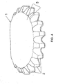
- Fig. 4 a schematic representation of a virtually finely cut sprocket with the expected indentation
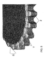
- Fig. 5 a schematic representation of the topography of the determined indentation
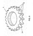
- Fig. 6 a finely cut sprocket with sharp-edged teeth according to the method of the invention
- Fig. 7 a sectional view of the first working stage
- Fig. 8 a sectional view of the second stage
- Fig. 9 a detail X from the Fig. 7 with enlarged representation of the die in the second working stage.
- the Fig. 1 shows a sprocket 1 from the feed side A, which was prepared by conventional fine blanking. At the individual teeth 2 of the sprocket 1 of the feeder 3 can be seen, which increases with decreasing corner radius and increasing sheet thickness.
- the insertion depth t can be about 20% and the insertion width b about 30% of the sheet thickness (see Fig. 2 ), so that the functional surface on the teeth of the sprocket be significantly reduced and a thicker starting material must be used to ensure the parts function, such as torque transmission.
- this feeder 3 is variably controlled in a wide range, ie a functionally predetermined for a finished part feeder can be achieved.
- the collection of finished parts in the range between normal values and zero (without indentation) should be adjustable.
- the sequence of the method according to the invention is explained in more detail below using the example of the sprocket 1 made of a cold extrusion steel of steel grade 16MnCr5 / 1.7131 with a material thickness s of 7 mm.
- the Fig. 2 shows on a tooth 2 of the sprocket 1, the geometric conditions for a desired indentation 4.
- the insertion depth t should be 0.8 mm and the feed width b should be 2.3 mm at both tooth flanks.
- the functional width FB on the tooth should reach 5.4 mm.
- the inventive method initially takes place in several steps, which are arranged upstream of the actual two-stage manufacturing process of the sprocket.
- a first step the expected indentation 5 by a normal fine cutting of those Areas of the sprocket 1 virtually determined that are to be influenced.
- the result of this simulation shows Fig. 4 ,
- the indentation can be thought of as a volume defect on the finished part, i. at the sprocket 1, define.
- the missing volume can be determined, which is necessary to achieve a desired final contour on the sprocket.
- the topography T is determined on the expected indentation 5 and the topography of the desired indentation 4 on the finished part (see Fig. 5 ) and from this in the fourth step in the corresponding area of the sprocket 1, a desired contour SK determined by a material addition, which complements the missing volume in the region of the collection (see Fig. 3 ). This results in a blank 6 with the desired contour SK.
- the virgin fineblanking of the corrected contour prepares the blank for the virtual forming in the fifth work step.
- the blank is then virtually transformed and checked the adjusting indentation. This is repeated until the desired indentation is achieved.
- the actual manufacturing process of the sprocket 1 is carried out in two stages, which are summarized in a tool, in a fine blanking stage and a subsequent forming stage.
- This fine blanking differs from conventional fine blanking in that the blank 6 is cut out to the final contour at least in the area of the feeder in a defined material addition to the finished part, the size of which is set to a volume of material which reduces the volume defect caused by the feeder to a predetermined dimension complements, compensates or exceeds.
- this volume of material is displaced by a forming process counter to the cutting direction of the first stage on the cutting line of the blank for targeted filling of the resulting intake, so that the desired indentation is obtained on the finished part.
- Fig. 6 this condition is shown on the finished part. It can be seen that the teeth are sharp-edged.
- the Fig. 7 shows the basic structure of the first stage, which includes an upper part 7 and a lower part 8.
- the upper part 7 essentially includes a cutting punch 9, which is guided on a guide plate 10 and a pressure plate 11 for the cutting punch 9.
- the lower part 8 is formed from a cutting plate 12, a punch 13 and an ejector 14.
- the strip of tape, not shown, of application steel with a thickness of 7 mm, from which according to the inventive method sprockets 1 are to be produced, is shown in FIG Setting condition of the tool between the guide plate 10 and cutting plate 12 is clamped.
- Fig. 8 the second working stage is shown, which also divides into a top and bottom.
- the upper part contains as main assemblies a guide plate 15, a punch 16 and a pressure plate 17 for the punch 16.
- the lower part essentially includes a die 18 and an ejector 19. The cut in the first stage blank 6 is clamped between the punch 16 and ejector 19th ,
- the cutting punch 9 and the cutting plate 12 are designed so that the blank 6 is cut with the previously determined target contour SK, which is slightly larger compared to the final contour EK on the sprocket 1. This is especially true for those areas that can be expected a large move. The more the indentation is to be reduced, the larger must be the difference between the nominal contour SK and the final contour EK.
- the die 18 has the final contour EK of the sprocket 1 (finished part).
- the die inlet 20 has an angled portion 21 of about 10 °, which merges with a sharp transition 22 in the vertical end contour EK.
- Fig. 9 shown. It can be seen that the material protruding from the blank 6 due to the addition of material is shifted in height and thus partially or completely fills the area of the feeder, or in extreme cases also an elevation in this Range can be generated. This depends on the size of the material addition, so that the collection of precast parts with corners, sharp transitions, teeth o. The like. According to their function as desired adjustable or even completely compensated.
Abstract
Description
Die Erfindung betrifft ein Verfahren zum Beeinflussen der Schnitt- und Funktionsfläche, insbesondere des Einzugs, an feingeschnittenen Fertigteilen, beispielsweise eines Zahnrades O. dgl., aus einem Bandstreifen, bei dem der Bandstreifen zwischen einem zumindest aus Schneidstempel, Führungsplatte für den Schneidstempel umfassenden Oberteil und einem zumindest Schneidplatte und Auswerfer enthaltenden Unterteil beim Schließen geklemmt und in einer ersten Arbeitsstufe ein Rohteil aus dem Bandstreifen mit Einzug ausgeschnitten wird:The invention relates to a method for influencing the cutting and functional surface, in particular of the feeder, on finely cut finished parts, such as a gear O. The like., From a tape strip, wherein the tape strip between a comprehensive at least from cutting punch, guide plate for the cutting punch top and a lower part containing at least cutting plate and ejector clamped when closing and in a first stage of work, a blank is cut out of the tape strip with indentation:
Die Erfindung betrifft ferner eine Vorrichtung zum Beeinflussen der Schnitt- und Funktionsfläche, insbesondere des Einzugs an feingeschnittenen Fertigteilen, beispielsweise eines Zahnrades o. dgl., aus einem Bandstreifen, mit einem zweiteiligen Werkzeug, das in der ersten Arbeitsstufe mindestens einen Schneidstempel, eine Führungsplatte für den Schneidstempel, einen Auswerfer und eine Schneidplatte umfasst, wobei der Bandstreifen zwischen Führungsplatte und Schneidplatte beim Feinschneiden eines Rohteiles eingeklemmt ist.The invention further relates to a device for influencing the cutting and functional surface, in particular the collection of finely cut finished parts, such as a gear o. The like., From a tape strip, comprising a two-part tool, which comprises in the first stage at least one cutting punch, a guide plate for the cutting punch, an ejector and a cutting plate, wherein the tape strip between the guide plate and cutting plate is clamped during fine blanking of a blank.
In der Feinschneid- und Umformtechnik werden vorwiegend Stähle verarbeitet. Dabei erstreckt sich die Vielfalt verwendeter Werkstoffe von einfachen Baustählen bis hin zu hochfesten Feinkornstählen. Die Ressource "Werkstoff" hat in den letzten Jahren stark an Bedeutung gewonnen. Mit einer optimalen Werkstoffausnutzung lassen sich die Herstellkosten eines Bauteiles wesentlich beeinflussen. Die hochfesten Stähle ermöglichen dünnwandigere Bauteile bei gleichem Festigkeitsverhalten.In fineblanking and forming technology, mainly steels are processed. The variety of materials used extends from simple structural steels to high-strength fine-grained steels. The resource "material" has gained in importance in recent years. With optimal material utilization, the production costs of a component can be significantly influenced. The high-strength steels enable thinner-walled components with the same strength behavior.
Typisches Merkmal von Feinschneidteilen ist der Kanteneinzug. Insbesondere in Eckenpartien stellt sich der Einzug ein, der mit kleiner werdendem Eckenradius und steigender Blechdicke zunimmt. Die Einzugstiefe kann rd. 20% und die Einzugsbreite etwa 30% der Blechdicke oder mehr betragen (siehe
Der Stanzeinzug reduziert deshalb die Teilefunktion, und zwingt den Hersteller zur Verwendung eines dickeren Ausgangsmaterials.A typical feature of fineblanking parts is the edge feed. In particular, in corner parts, the feeder, which increases with decreasing the corner radius and increasing sheet thickness. The insertion depth can be approx. 20% and the feed width about 30% of the sheet thickness or more (see
The punch pull therefore reduces the parting function and forces the manufacturer to use a thicker stock.
Es sind eine ganze Reihe von Lösungen bekannt, die versuchen, den Kanteneinzug entweder durch Nachschneiden (
Die bekannten Lösungen nach
Bei der bekannten Lösung gemäß
Des Weiteren ist aus der
Der Nachteil all dieser bekannten technischen Lösungen besteht, darin, dass der beim Feinschneiden entstehende Einzug lediglich vermindert, aber letztendlich nicht beseitigt und nicht gezielt beeinflusst werden kann.There is a whole series of solutions known which try to cut the edges either by trimming (
The known solutions
In the known solution according to
Furthermore, from the
The disadvantage of all these known technical solutions is that the resulting during fine cutting indentation only reduced, but ultimately not eliminated and can not be selectively influenced.
Bei diesem Stand der Technik liegt der Erfindung die Aufgabe zugrunde, ein Verfahren und eine Vorrichtung zum gezielten Beeinflussen der Schnitt- und Funktionsfläche, insbesondere des Einzugs beim Herstellen von Fertigteilen wie beispielsweise Zahnräder bereitzustellen, in dem der Kanteneinzug bei gleichzeitiger Beibehaltung der Funktionsflächen unter Einsparung von Material gezielt beeinflusst oder gänzlich beseitigbar ist.In this prior art, the present invention seeks to provide a method and apparatus for selectively influencing the cutting and functional surface, in particular of the feeder during the manufacture of finished parts such as gears, in which the edge feed while maintaining the functional surfaces while saving Material is specifically influenced or completely eliminated.
Diese Aufgabe wird durch ein Verfahren der eingangs genannten Gattung mit den Merkmalen des Anspruchs 1 und durch eine Vorrichtung mit den Merkmalen des Anspruchs 5 gelöst.This object is achieved by a method of the type mentioned with the features of
Vorteilhafte Ausgestaltungen des Verfahrens und der Vorrichtung sind den Unteransprüchen entnehmbar.Advantageous embodiments of the method and the device are the dependent claims.
Die erfindungsgemäße Lösung geht von der Erkenntnis aus, den Einzug durch eine Materialzugabe an der Kontur eines Rohteils bereits vor der Feinschneidoperation gezielt zu beeinflussen und dessen Größe auf ein gewünschtes Maß einzustellenThe solution according to the invention is based on the knowledge to specifically influence the indentation by adding material to the contour of a blank already before the fineblanking operation and to adjust its size to a desired level
Dies wird dadurch erreicht, dass das Rohteil zumindest im Bereich des Einzugs in einer gegenüber dem Fertigteil definiert gewählten Materialzugabe zur Kontur ausgeschnitten wird, deren Größe innerhalb der ersten Arbeitsstufe auf ein Materialvolumen eingestellt wird, das den durch den Einzug hervorgerufenen Volumendefekt in einen vorgegebenen Maß ergänzt, ausgleicht oder übertrifft, und dass anschließend in einer zweiten Arbeitsstufe dieses Materialvolumen durch einen Umformvorgang entgegen der Schneidrichtung der ersten Arbeitsstufe an der Schnittlinie des Rohteils zum Auffüllen des entstandenen Einzugs verschoben wird.This is achieved in that the blank is cut out, at least in the region of the feeder in a defined relative to the finished part material allowance to the contour whose size is set to a volume of material within the first stage, which complements the volume defect caused by the feeder to a predetermined extent , compensates or exceeds, and that then in a second stage of this material volume is moved by a forming operation counter to the cutting direction of the first stage on the cutting line of the blank to fill the resulting intake.
Von besonderem Vorteil ist, dass die Größe der Materialzugabe zur Kontur in Abhängigkeit der Geometrie des Fertigteiles, der Festigkeit und Art des Materials, der Dicke des Fertigteils durch eine virtuelle Feinschneidsimulation und die Größe des zu verschiebenden Materialvolumens durch eine virtuelle Umformsimulation vor dem Feinschneiden bestimmt wird.It is of particular advantage that the size of the material addition to the contour is determined by a virtual reshaping simulation before the fine blanking depending on the geometry of the finished part, the strength and type of material, the thickness of the finished part by a virtual fine blanking simulation and the size of the material to be moved ,
In einer bevorzugten Ausführungsvariante läuft das erfindungsgemäße Verfahren in folgenden Schritten ab:
- a) Durchführen einer Feinschneidsimulation in demjenigen Bereich am Fertigteil, welcher beeinflusst werden soll, und Ermitteln eines virtuellen Einzugs,
- b) Bestimmen der Topografie des zu erwartenden Einzugs aus Schritt a) und der Topografie eines gewünschten Einzugs am Fertigteil,
- c) Bestimmen des fehlenden Volumens aus Schritt b), um die gewünschte Endkontur beim Einzug am Fertigteil zu erreichen,
- d) Bestimmen einer korrigierten Kontur für den entsprechenden Bereich (Sollkontur) aus den Schritten a) bis c) durch Materialzugabe, um das fehlende b) Volumen im Bereich des Einzugs zu ergänzen,
- e) Durchführen eines erneuten virtuellen Feinschneidens der korrigierten Kontur (Sollkontur) und Bestimmen der Topografie des sich einstellenden Einzugs,
- f) Durchführen eines virtuellen Umformens der feingeschnittenen, korrigierten Kontur mit einer Umformmatrize, welche nach der Endkontur des Fertigteils ausgelegt ist und Bestimmen des sich einstellenden korrigierten Einzuges,
- g) Wiederholen der Schritte d) bis f) bis der gewünschte Einzug erreicht wird,
- h) Auslegen von Schneidplatte und Schneidstempel der ersten Arbeitsstufe auf die mit den Schritten a) bis g) gefundene korrigierte Kontur (Sollkontor) des Rohteils.
- a) performing a fine blanking simulation in the area on the finished part which is to be influenced and determining a virtual feed,
- b) determining the topography of the expected intake from step a) and the topography of a desired intake on the finished part,
- c) determining the missing volume from step b) in order to achieve the desired final contour when pulling in on the finished part,
- d) determining a corrected contour for the corresponding area (target contour) from the steps a) to c) by adding material to supplement the missing b) volume in the region of the intake,
- e) performing a new virtual fineblanking of the corrected contour (nominal contour) and determining the topography of the self-adjusting intake,
- f) carrying out a virtual reshaping of the finely cut, corrected contour with a forming die, which is designed according to the final contour of the finished part, and determining the resulting corrected retraction,
- g) repeating steps d) to f) until the desired intake is achieved,
- h) laying out of the cutting plate and cutting punch of the first working step on the with the steps a) to g) found corrected contour (Sollkontor) of the blank.
Das erfindungsgemäße Verfahren ist variabel einsetzbar. So kann es überall dort zum Einsatz gebracht werden, wo der Einzug kompensiert werden soll, beispielsweise zum Herstellen von Kettenrädern, Zahnrädern, Zahnpumpenräder, Zahnsegmente oder Teilen mit funktionalen Ecken.The method according to the invention can be used variably. So it can be used anywhere where the feeder is to be compensated, for example for the production of sprockets, gears, Zahnpumpenräder, toothed segments or parts with functional corners.
Die Aufgabe wird weiterhin durch eine Vorrichtung dadurch gelöst, dass das Werkzeug in einer zweiten Arbeitsstufe einen Stempel und eine mit einer dem Stempel zugewandten Anwinklung versehene, eine Endkontur aufweisende Matrize und einen Auswerfer enthält, wobei das zwischen Stempel und Auswerfer geklemmte, mit einer Materialzugabe ausgeschnittene Rohteil in die Matrize zurückgedrückt wird, so dass die Materialzugabe entlang der Schnittfläche des feingeschnittenen Rohteils zum gezielten Auffüllen des Einzugs verschoben wird.The object is further achieved by a device solved in that the tool in a second working stage a punch and a provided with a punch facing angled, having a final contour die and an ejector, wherein the clamped between the punch and ejector, with a material addition cut blank is pushed back into the die, so that the material addition is moved along the cutting surface of the finely cut blank for targeted filling of the feeder.
In weiterer Ausgestaltung der erfindungsgemäßen Vorrichtung hat die Matrize eine Anwinklung von etwa 8 bis 15°, vorzugsweise 10°, die mit einem scharfen Übergang zur senkrechten Endkontur versehen ist.In a further embodiment of the device according to the invention, the die has an angling of about 8 to 15 °, preferably 10 °, which is provided with a sharp transition to the vertical end contour.
Die erfindungsgemäße Vorrichtung ist einfach und robust im Aufbau und hat den großen Vorteil, dass die erste Arbeitsstufe (Feinschneiden) und die zweite Arbeitsstufe (Umformen) innerhalb eines Werkzeuges durchgeführt werden können.The inventive device is simple and robust in construction and has the great advantage that the first stage (fine blanking) and the second stage (forming) can be performed within a tool.
Weitere Vorteile und Einzelheiten ergeben sich aus der nachfolgenden Beschreibung unter Bezugnahme auf die beigefügten Zeichnungen.Further advantages and details will become apparent from the following description with reference to the accompanying drawings.
Die Erfindung soll nachstehend an einem Ausführungsbeispiel näher erläutert werden.The invention will be explained in more detail below using an exemplary embodiment.
Es zeigenShow it
Die
An den einzelnen Zähnen 2 des Kettenrades 1 ist der Einzug 3 zu erkennen, der mit kleiner werdenden Eckenradius und steigender Blechdicke zunimmt. Die Einzugstiefe t kann etwa 20% und die Einzugsbreite b ca. 30% der Blechdicke ausmachen (siehe
At the
Mit dem erfindungsgemäßen Verfahren soll dieser Einzug 3 in einem großen Bereich variabel gesteuert, d.h. ein für ein Fertigteil funktional vorgegebener Einzug erreicht werden. Mit anderen Worten soll der Einzug an Fertigteilen im Bereich zwischen normalen Werten und Null (ohne Einzug) einstellbar sein.
Der Ablauf des erfindungsgemäßen Verfahrens wird nachfolgend am Beispiel des Kettenrades 1 aus einem Kaltfließpressstahl der Stahlqualität 16MnCr5/1.7131 mit einer Materialdicke s vom 7 mm näher erläutert.With the method according to the invention this
The sequence of the method according to the invention is explained in more detail below using the example of the
Die
Das erfindungsgemäße Verfahren läuft zunächst in mehreren Arbeitsschritten ab, die dem eigentlichen zweistufigen Herstellungsvorgang des Kettenrades vorgeordnet sind. In einem ersten Arbeitsschritt wird der zu erwartende Einzug 5 durch ein normales Feinschneiden an denjenigen Bereichen des Kettenrades 1 virtuell ermittelt, die beeinflusst werden sollen. Das Ergebnis dieser Simulation zeigt
Der Einzug lässt sich als ein Volumendefekt am Fertigteil, d.h. am Kettenrad 1, definieren. Somit kann aus dem gewünschten Einzug 4 und dem erwarteten Einzug 5 im zweiten Arbeitsschritt das fehlende Volumen bestimmt werden, das nötig ist, um eine gewünschte Endkontur am Kettenrad zu erreichen.The indentation can be thought of as a volume defect on the finished part, i. at the
Im den sich anschließenden dritten Arbeitsschritt wird die Topographie T am zu erwartenden Einzug 5 und die Topographie des gewünschten Einzugs 4 am Fertigteil festgestellt (siehe
Durch das erneute virtuelle Feinschneiden der korrigierten Kontur (Sollkontur) wird das Rohteil im fünften Arbeitsschritt für die virtuelle Umformung vorbereitet.
Im sechsten Arbeitsschritt wird das Rohteil dann virtuell umgeformt und der sich einstellende Einzug überprüft. Dies wiederholt sich, bis der gewünschte Einzug erreicht ist.The virgin fineblanking of the corrected contour (target contour) prepares the blank for the virtual forming in the fifth work step.
In the sixth step, the blank is then virtually transformed and checked the adjusting indentation. This is repeated until the desired indentation is achieved.
Nach Ablauf dieser Arbeitsschritte können im letzten Arbeitsschritt der Schneidstempel und die Schneidplatte für eine erste Arbeitsstufe auf die ermittelte Sollkontur SK des Rohteils 6 und die Matrize auf die ermittelte Endkontur EK am Fertigteil ausgelegt werden.After the end of these steps can in the last step of the cutting punch and the cutting plate for a first stage on the determined target contour SK of the blank 6 and the die on the determined final contour EK are designed on the finished part.
Der eigentliche Herstellungsvorgang des Kettenrades 1 erfolgt in zwei Arbeitsstufen, die in einem Werkzeug zusammengefasst sind, und zwar in einer Feinschneidstufe und einer nachfolgenden Umformstufe. Dieses Feinschneiden unterscheidet gegenüber dem herkömmlichen Feinschneiden dadurch, dass das Rohteil 6 zumindest im Bereich des Einzugs in einer gegenüber dem Fertigteil definiert gewählten Materialzugabe zur Endkontur ausgeschnitten wird, deren Größe auf ein Materialvolumen eingestellt wird, das den durch den Einzug hervorgerufenen Volumendefekt in einen vorgegebenen Maß ergänzt, ausgleicht oder übertrifft.
In der zweiten Arbeitsstufe wird dieses Materialvolumen durch einen Umformvorgang entgegen der Schneidrichtung der ersten Arbeitsstufe an der Schnittlinie des Rohteils zum gezielten Auffüllen des entstandenen Einzugs verschoben, so dass der gewünschte Einzug am Fertigteil erhalten wird.
In
In the second stage, this volume of material is displaced by a forming process counter to the cutting direction of the first stage on the cutting line of the blank for targeted filling of the resulting intake, so that the desired indentation is obtained on the finished part.
In
Die
In
Der Schneidstempel 9 und die Schneidplatte 12 sind so ausgelegt, dass das Rohteil 6 mit der zuvor bestimmten Sollkontur SK ausgeschnitten wird, die gegenüber der Endkontur EK am Kettenrad 1 etwas größer ist. Dies gilt insbesondere für diejenigen Bereiche, die einen großen Einzug erwarten lassen. Je mehr der Einzug reduziert werden soll, desto größer muss die Differenz zwischen der Sollkontur SK und der Endkontur EK sein.The cutting punch 9 and the cutting
In der zweiten Arbeitsstufe wird das gegenüber der Endkontur EK etwas größere ausgeschnittene Rohteil 6 durch den Stempel 16 in die Matrize 18 gedrückt. Die Matrize 18 weist die Endkontur EK des Kettenrades 1 (Fertigteil) auf. Der Matrizeneinlauf 20 besitzt eine Anwinklung 21 von etwa 10°, die mit einem scharfen Übergang 22 in die vertikale Endkontur EK übergeht. Diese Verhältnisse sind in der
Bezugszeichenliste
- Kettenrad
- 1
Zähne von 1- 2
Einzug bei 2- 3
- Gewünschter Einzug
- 4
- Erwarteter Einzug
- 5
- Rohteil
- 6
- Oberteil
- 7
- Unterteil
- 8
- Schneidstempel
- 9
- Führungsplatte für 9
- 10
- Druckplatte für 9
- 11
- Schneidplatte
- 12
- Lochstempel
- 13
- Auswerfer
- 14
Führungsplatte für 16- 15
- Stempel
- 16
Druckplatte für 16- 17
- Matrize
- 18
- Auswerfer
- 19
- Matrizeneinlauf
- 20
Anwinklung von 20- 21
- Übergang
- 22
- Einzugsbreite
- b
- Endkontur
- EK
- Funktionsbreite
- FB
- Sollkontur
- SK
- Materialdicke
- s
- Einzugstiefe
- t
- Topographie
- T
- Sprocket
- 1
- Teeth of 1
- 2
- Moving in at 2
- 3
- Desired move-in
- 4
- Expected move-in
- 5
- blank
- 6
- top
- 7
- lower part
- 8th
- cutting punch
- 9
- Guide plate for 9
- 10
- Pressure plate for 9
- 11
- cutting board
- 12
- punch
- 13
- ejector
- 14
- Guide plate for 16
- 15
- stamp
- 16
- Pressure plate for 16
- 17
- die
- 18
- ejector
- 19
- Matrizeneinlauf
- 20
- Angling of 20
- 21
- crossing
- 22
- throat width
- b
- final contour
- EK
- width function
- FB
- target contour
- SK
- material thickness
- s
- retraction depth
- t
- topography
- T
Claims (6)
Priority Applications (5)
| Application Number | Priority Date | Filing Date | Title |
|---|---|---|---|
| EP20100001351 EP2357048B1 (en) | 2010-02-10 | 2010-02-10 | Method and device for influencing the cutting and functional areas on fine-cut finished parts |
| US13/024,114 US8826540B2 (en) | 2010-02-10 | 2011-02-09 | Method and device for influencing the cut and functional face on fine-blanked finished parts |
| JP2011025592A JP5902392B2 (en) | 2010-02-10 | 2011-02-09 | Apparatus and method for influencing the sheared functional end of a precision shear finished member |
| KR1020110012013A KR101823568B1 (en) | 2010-02-10 | 2011-02-10 | Method and device for influencing the sheared and functional edge at fine blanked finished parts |
| CN201110081562.XA CN102189168B (en) | 2010-02-10 | 2011-02-10 | Method and device for influencing the cut and functional face on fine-blanked finished parts |
Applications Claiming Priority (1)
| Application Number | Priority Date | Filing Date | Title |
|---|---|---|---|
| EP20100001351 EP2357048B1 (en) | 2010-02-10 | 2010-02-10 | Method and device for influencing the cutting and functional areas on fine-cut finished parts |
Publications (2)
| Publication Number | Publication Date |
|---|---|
| EP2357048A1 true EP2357048A1 (en) | 2011-08-17 |
| EP2357048B1 EP2357048B1 (en) | 2013-06-05 |
Family
ID=42272351
Family Applications (1)
| Application Number | Title | Priority Date | Filing Date |
|---|---|---|---|
| EP20100001351 Active EP2357048B1 (en) | 2010-02-10 | 2010-02-10 | Method and device for influencing the cutting and functional areas on fine-cut finished parts |
Country Status (5)
| Country | Link |
|---|---|
| US (1) | US8826540B2 (en) |
| EP (1) | EP2357048B1 (en) |
| JP (1) | JP5902392B2 (en) |
| KR (1) | KR101823568B1 (en) |
| CN (1) | CN102189168B (en) |
Cited By (1)
| Publication number | Priority date | Publication date | Assignee | Title |
|---|---|---|---|---|
| EP2926921A3 (en) * | 2014-03-17 | 2015-12-30 | Toa Forging Co., Ltd. | Method of manufacturing metal plate having hole, metal plate with hole, external gear with peripheral hole, external gear, metal plate for cam, method of manufacturing metal plate, and metal plate |
Families Citing this family (5)
| Publication number | Priority date | Publication date | Assignee | Title |
|---|---|---|---|---|
| CN103521592B (en) * | 2013-02-27 | 2015-10-28 | 上海汇众汽车制造有限公司 | Improve the method for quality of fracture of blank of high-strength steel |
| CN103223536A (en) * | 2013-05-09 | 2013-07-31 | 天津市中环三峰电子有限公司 | Device for preventing die core from corner collapse |
| DE102014000299B3 (en) * | 2014-01-15 | 2015-07-16 | Rixen Wolfgang | Method for producing passages in a metallic body by means of high-speed shear cutting and its use |
| CN109033512B (en) * | 2018-06-15 | 2023-07-18 | 华中科技大学鄂州工业技术研究院 | Determination method for optimal cutting edge shape of fine blanking die |
| CN113560418A (en) * | 2021-07-26 | 2021-10-29 | 苏州东风精冲工程有限公司 | Small-collapse-angle fine blanking forming method |
Citations (6)
| Publication number | Priority date | Publication date | Assignee | Title |
|---|---|---|---|---|
| US3724305A (en) * | 1969-11-15 | 1973-04-03 | K Kondo | Precision shearing method |
| CH665367A5 (en) * | 1984-09-17 | 1988-05-13 | Feintool Ag | Eliminating material burr at edges of press-cut component - by at least one corrective cutting step on step-wise moving metal strip |
| US4876876A (en) * | 1987-10-27 | 1989-10-31 | Mazda Motor Corporation | Dies for forging gear-shaped part made of sheet metal |
| DE19707753A1 (en) * | 1996-02-26 | 1997-08-28 | Mitsubishi Motors Corp | Metal workpiece smoothed by pressure ram |
| DE19738635A1 (en) * | 1997-09-04 | 1999-03-18 | Feintool Int Holding | Process for the production of exact cut surfaces |
| DE102007005847A1 (en) * | 2006-02-20 | 2007-08-30 | Tsubakimoto Chain Co. | Chain wheel e.g. drive chain wheel, manufacturing method for use in internal combustion engine, involves designing tooth points of chain wheel with rounded rear sides, and designing rounded front sides at points by pressing points |
Family Cites Families (22)
| Publication number | Priority date | Publication date | Assignee | Title |
|---|---|---|---|---|
| JPS56134026A (en) * | 1980-03-25 | 1981-10-20 | Tsubakimoto Chain Co | Blanking method |
| DE3324680A1 (en) * | 1983-07-08 | 1985-01-24 | DAKO-Werkzeugfabriken David Kotthaus GmbH & Co KG, 5630 Remscheid | METHOD FOR FINE CUTTING WORKPIECES AND FINE CUTTING TOOL FOR EXERCISING THE METHOD |
| DE3931320C1 (en) * | 1989-09-20 | 1991-08-08 | Feintool International Holding, Lyss, Ch | |
| US5320013A (en) * | 1991-06-20 | 1994-06-14 | Fuji Electric Co., Ltd. | Method of blanking metal foil on piezoelectric actuator operated press, and die sets for practicing the method |
| US5263353A (en) * | 1992-06-29 | 1993-11-23 | The Whitaker Corporation | Punch and die apparatus for producing flat stamped contact devices having improved contact edge surfaces |
| CN1102144A (en) * | 1993-10-26 | 1995-05-03 | 青岛建筑工程学院 | Spur gear precision die stamping-push-press forming process and its equipment |
| JP2640638B2 (en) * | 1995-04-07 | 1997-08-13 | 小川工業株式会社 | Ring gear manufacturing method by precision die forging |
| DE19608551A1 (en) * | 1996-03-06 | 1997-09-11 | Zahnradfabrik Friedrichshafen | Method and device for producing stamped parts |
| DE19629984A1 (en) | 1996-07-25 | 1998-01-29 | Zoltan Berger | Process for the production of a consumable |
| US6353768B1 (en) * | 1998-02-02 | 2002-03-05 | General Electric Company | Method and apparatus for designing a manufacturing process for sheet metal parts |
| JP2975926B1 (en) * | 1998-06-04 | 1999-11-10 | 株式会社メタルアート | Forming device for annular internal gear with chamfer |
| US7194388B2 (en) * | 2002-03-25 | 2007-03-20 | Alcoa Inc. | Method for determining a die profile for forming a metal part having a desired shape and associated methods |
| CN100333852C (en) * | 2002-06-06 | 2007-08-29 | 武汉华夏精冲技术有限公司 | Precise punch technology for manufacturing circular or sectorial gear |
| US7415400B2 (en) * | 2002-10-15 | 2008-08-19 | Livermore Software Technology Corporation | System, method, and device for designing a die to stamp metal parts to an exact final dimension |
| ITPD20020274A1 (en) * | 2002-10-22 | 2004-04-23 | Pegasus Srl | METHOD FOR THE SHEARING OF METAL PARTS. |
| US7627389B2 (en) * | 2005-06-16 | 2009-12-01 | Klingelnberg Gmbh | Method and apparatus for the free-form optimization of bevel and hypoid gears |
| ATE420741T1 (en) * | 2006-02-03 | 2009-01-15 | Feintool Ip Ag | METHOD AND TOOL FOR FINE BLANKING OF WORKPIECES WITH SMALL CORNER RADII AND MASSIVELY REDUCED FEED IN A ONE-STAGE ARRANGEMENT |
| ATE427798T1 (en) * | 2006-09-01 | 2009-04-15 | Feintool Ip Ag | METHOD AND TOOL FOR PRODUCING THREE-DIMENSIONAL FITTINGS PRODUCED BY FORMING AND FINE BLANKING PROCESSES |
| ATE489181T1 (en) | 2007-09-14 | 2010-12-15 | Feintool Ip Ag | METHOD AND DEVICE FOR PRODUCING STAMPED PARTS WITH ENLARGED FUNCTIONAL AREA |
| DE502007004202D1 (en) * | 2007-09-14 | 2010-08-05 | Feintool Ip Ag | Method and device for fine cutting and forming a workpiece |
| PT2042249E (en) * | 2007-09-26 | 2010-06-07 | Feintool Ip Ag | Method and device for manufacturing stamping parts with a largely smooth cutting plane and larger functional area |
| CN101214510B (en) * | 2008-01-08 | 2010-10-13 | 江苏森威集团有限责任公司 | Blind hole internal gear precision forming method and internal tooth forming mold |
-
2010
- 2010-02-10 EP EP20100001351 patent/EP2357048B1/en active Active
-
2011
- 2011-02-09 JP JP2011025592A patent/JP5902392B2/en active Active
- 2011-02-09 US US13/024,114 patent/US8826540B2/en active Active
- 2011-02-10 CN CN201110081562.XA patent/CN102189168B/en active Active
- 2011-02-10 KR KR1020110012013A patent/KR101823568B1/en active IP Right Grant
Patent Citations (6)
| Publication number | Priority date | Publication date | Assignee | Title |
|---|---|---|---|---|
| US3724305A (en) * | 1969-11-15 | 1973-04-03 | K Kondo | Precision shearing method |
| CH665367A5 (en) * | 1984-09-17 | 1988-05-13 | Feintool Ag | Eliminating material burr at edges of press-cut component - by at least one corrective cutting step on step-wise moving metal strip |
| US4876876A (en) * | 1987-10-27 | 1989-10-31 | Mazda Motor Corporation | Dies for forging gear-shaped part made of sheet metal |
| DE19707753A1 (en) * | 1996-02-26 | 1997-08-28 | Mitsubishi Motors Corp | Metal workpiece smoothed by pressure ram |
| DE19738635A1 (en) * | 1997-09-04 | 1999-03-18 | Feintool Int Holding | Process for the production of exact cut surfaces |
| DE102007005847A1 (en) * | 2006-02-20 | 2007-08-30 | Tsubakimoto Chain Co. | Chain wheel e.g. drive chain wheel, manufacturing method for use in internal combustion engine, involves designing tooth points of chain wheel with rounded rear sides, and designing rounded front sides at points by pressing points |
Cited By (2)
| Publication number | Priority date | Publication date | Assignee | Title |
|---|---|---|---|---|
| EP2926921A3 (en) * | 2014-03-17 | 2015-12-30 | Toa Forging Co., Ltd. | Method of manufacturing metal plate having hole, metal plate with hole, external gear with peripheral hole, external gear, metal plate for cam, method of manufacturing metal plate, and metal plate |
| TWI641433B (en) * | 2014-03-17 | 2018-11-21 | 日商東亞鍛工所股份有限公司 | Method of manufacturing metal plate having hole, metal plate with hole, external gear with peripheral hole and method for producing the same, external gear, metal plate for cam, method of manufacturing metal plate, and metal plate |
Also Published As
| Publication number | Publication date |
|---|---|
| JP5902392B2 (en) | 2016-04-13 |
| EP2357048B1 (en) | 2013-06-05 |
| KR101823568B1 (en) | 2018-01-30 |
| CN102189168B (en) | 2015-04-01 |
| KR20110093706A (en) | 2011-08-18 |
| US8826540B2 (en) | 2014-09-09 |
| JP2011161517A (en) | 2011-08-25 |
| US20110192028A1 (en) | 2011-08-11 |
| CN102189168A (en) | 2011-09-21 |
Similar Documents
| Publication | Publication Date | Title |
|---|---|---|
| EP2036631B1 (en) | Method and device for manufacturing stamping parts with a larger functional area | |
| EP1815922B1 (en) | Method of and tool for fine-cutting pieces with small edge radius and strongly reduced depth in a single step arrangement | |
| EP2512702B1 (en) | Method and device for producing a half-shell part | |
| EP2701861B1 (en) | Method and device for producing flangeless drawn parts | |
| EP2508274B1 (en) | Method and device for increasing the bearing area of a fine blanked workpiece with a tooth, a tooth section or the like | |
| EP2357048B1 (en) | Method and device for influencing the cutting and functional areas on fine-cut finished parts | |
| EP2259883B1 (en) | Method for controlling the flow of material when deep-drawing a workpiece, and deep-drawing device | |
| EP2042249A1 (en) | Method and device for manufacturing stamping parts with a largely smooth cutting plane and larger functional area | |
| EP2701862B1 (en) | Method and device for producing flanged drawn parts with simultaneous trimming | |
| DE102010048104B3 (en) | Method for manufacturing tool i.e. deep-drawing tool, to e.g. cut metal sheet material, involves adjusting die contour by linear displacement of die contour, forming stamper with stamper contour, and forming die with adjusted die contour | |
| EP2861368B1 (en) | Method for generating a gear tooth system, and a gear cutting machine that is operated using said method | |
| DE102013112123B4 (en) | Metal sleeve and method for its production | |
| EP2542363B1 (en) | Method and device for drawing and trimming metal sheets | |
| DE102011003252A1 (en) | rolling die | |
| DE3839800C2 (en) | ||
| DE102013001919B4 (en) | Process for producing a through hole in a metallic body and use of such a process | |
| DE102011102288B4 (en) | Device and method for producing a spur gear with a helical toothing | |
| EP1741497B9 (en) | Method and tool for producing without cutting a notch in a workpiece and workpiece with such notch | |
| DE3435424A1 (en) | PRESS STAMP AND METHOD FOR THE PRODUCTION THEREOF | |
| EP1459820B1 (en) | Method and machine arrangement for producing a threaded projection on a flat workpiece, in particular on a metal sheet | |
| EP0954397B1 (en) | Process and tool for manufacturing flat bearing shells | |
| DE102005015542A1 (en) | Cutting tool for burr-free creation of slot or other opening at metal object, comprising two cutting edges located opposite each other | |
| EP1870665A2 (en) | Method and kit for gauging a thread in at least two production steps | |
| DE1946151A1 (en) | Drawing tool made of hexagonal bars with lubrication system | |
| EP1321202B1 (en) | Manufacturing method and internal high pression forming tool for carrying out the manufacturing method |
Legal Events
| Date | Code | Title | Description |
|---|---|---|---|
| PUAI | Public reference made under article 153(3) epc to a published international application that has entered the european phase |
Free format text: ORIGINAL CODE: 0009012 |
|
| AK | Designated contracting states |
Kind code of ref document: A1 Designated state(s): AT BE BG CH CY CZ DE DK EE ES FI FR GB GR HR HU IE IS IT LI LT LU LV MC MK MT NL NO PL PT RO SE SI SK SM TR |
|
| AX | Request for extension of the european patent |
Extension state: AL BA RS |
|
| 17P | Request for examination filed |
Effective date: 20120208 |
|
| 17Q | First examination report despatched |
Effective date: 20120423 |
|
| GRAP | Despatch of communication of intention to grant a patent |
Free format text: ORIGINAL CODE: EPIDOSNIGR1 |
|
| GRAS | Grant fee paid |
Free format text: ORIGINAL CODE: EPIDOSNIGR3 |
|
| GRAA | (expected) grant |
Free format text: ORIGINAL CODE: 0009210 |
|
| AK | Designated contracting states |
Kind code of ref document: B1 Designated state(s): AT BE BG CH CY CZ DE DK EE ES FI FR GB GR HR HU IE IS IT LI LT LU LV MC MK MT NL NO PL PT RO SE SI SK SM TR |
|
| REG | Reference to a national code |
Ref country code: GB Ref legal event code: FG4D Free format text: NOT ENGLISH |
|
| REG | Reference to a national code |
Ref country code: CH Ref legal event code: EP |
|
| REG | Reference to a national code |
Ref country code: AT Ref legal event code: REF Ref document number: 615341 Country of ref document: AT Kind code of ref document: T Effective date: 20130615 |
|
| REG | Reference to a national code |
Ref country code: IE Ref legal event code: FG4D Free format text: LANGUAGE OF EP DOCUMENT: GERMAN |
|
| REG | Reference to a national code |
Ref country code: DE Ref legal event code: R096 Ref document number: 502010003495 Country of ref document: DE Effective date: 20130801 |
|
| PG25 | Lapsed in a contracting state [announced via postgrant information from national office to epo] |
Ref country code: GR Free format text: LAPSE BECAUSE OF FAILURE TO SUBMIT A TRANSLATION OF THE DESCRIPTION OR TO PAY THE FEE WITHIN THE PRESCRIBED TIME-LIMIT Effective date: 20130906 Ref country code: SE Free format text: LAPSE BECAUSE OF FAILURE TO SUBMIT A TRANSLATION OF THE DESCRIPTION OR TO PAY THE FEE WITHIN THE PRESCRIBED TIME-LIMIT Effective date: 20130605 Ref country code: ES Free format text: LAPSE BECAUSE OF FAILURE TO SUBMIT A TRANSLATION OF THE DESCRIPTION OR TO PAY THE FEE WITHIN THE PRESCRIBED TIME-LIMIT Effective date: 20130916 Ref country code: LT Free format text: LAPSE BECAUSE OF FAILURE TO SUBMIT A TRANSLATION OF THE DESCRIPTION OR TO PAY THE FEE WITHIN THE PRESCRIBED TIME-LIMIT Effective date: 20130605 Ref country code: NO Free format text: LAPSE BECAUSE OF FAILURE TO SUBMIT A TRANSLATION OF THE DESCRIPTION OR TO PAY THE FEE WITHIN THE PRESCRIBED TIME-LIMIT Effective date: 20130905 Ref country code: SI Free format text: LAPSE BECAUSE OF FAILURE TO SUBMIT A TRANSLATION OF THE DESCRIPTION OR TO PAY THE FEE WITHIN THE PRESCRIBED TIME-LIMIT Effective date: 20130605 Ref country code: FI Free format text: LAPSE BECAUSE OF FAILURE TO SUBMIT A TRANSLATION OF THE DESCRIPTION OR TO PAY THE FEE WITHIN THE PRESCRIBED TIME-LIMIT Effective date: 20130605 |
|
| REG | Reference to a national code |
Ref country code: CH Ref legal event code: NV Representative=s name: BOVARD AG, CH Ref country code: CH Ref legal event code: PUE Owner name: FEINTOOL INTERNATIONAL HOLDING AG, CH Free format text: FORMER OWNER: FEINTOOL INTELLECTUAL PROPERTY AG, CH |
|
| REG | Reference to a national code |
Ref country code: NL Ref legal event code: VDEP Effective date: 20130605 |
|
| REG | Reference to a national code |
Ref country code: LT Ref legal event code: MG4D |
|
| PG25 | Lapsed in a contracting state [announced via postgrant information from national office to epo] |
Ref country code: BG Free format text: LAPSE BECAUSE OF FAILURE TO SUBMIT A TRANSLATION OF THE DESCRIPTION OR TO PAY THE FEE WITHIN THE PRESCRIBED TIME-LIMIT Effective date: 20130905 Ref country code: HR Free format text: LAPSE BECAUSE OF FAILURE TO SUBMIT A TRANSLATION OF THE DESCRIPTION OR TO PAY THE FEE WITHIN THE PRESCRIBED TIME-LIMIT Effective date: 20130605 Ref country code: PL Free format text: LAPSE BECAUSE OF FAILURE TO SUBMIT A TRANSLATION OF THE DESCRIPTION OR TO PAY THE FEE WITHIN THE PRESCRIBED TIME-LIMIT Effective date: 20130605 |
|
| PG25 | Lapsed in a contracting state [announced via postgrant information from national office to epo] |
Ref country code: LV Free format text: LAPSE BECAUSE OF FAILURE TO SUBMIT A TRANSLATION OF THE DESCRIPTION OR TO PAY THE FEE WITHIN THE PRESCRIBED TIME-LIMIT Effective date: 20130605 |
|
| PG25 | Lapsed in a contracting state [announced via postgrant information from national office to epo] |
Ref country code: SK Free format text: LAPSE BECAUSE OF FAILURE TO SUBMIT A TRANSLATION OF THE DESCRIPTION OR TO PAY THE FEE WITHIN THE PRESCRIBED TIME-LIMIT Effective date: 20130605 Ref country code: IS Free format text: LAPSE BECAUSE OF FAILURE TO SUBMIT A TRANSLATION OF THE DESCRIPTION OR TO PAY THE FEE WITHIN THE PRESCRIBED TIME-LIMIT Effective date: 20131005 Ref country code: PT Free format text: LAPSE BECAUSE OF FAILURE TO SUBMIT A TRANSLATION OF THE DESCRIPTION OR TO PAY THE FEE WITHIN THE PRESCRIBED TIME-LIMIT Effective date: 20131007 Ref country code: CZ Free format text: LAPSE BECAUSE OF FAILURE TO SUBMIT A TRANSLATION OF THE DESCRIPTION OR TO PAY THE FEE WITHIN THE PRESCRIBED TIME-LIMIT Effective date: 20130605 Ref country code: EE Free format text: LAPSE BECAUSE OF FAILURE TO SUBMIT A TRANSLATION OF THE DESCRIPTION OR TO PAY THE FEE WITHIN THE PRESCRIBED TIME-LIMIT Effective date: 20130605 |
|
| REG | Reference to a national code |
Ref country code: DE Ref legal event code: R082 Ref document number: 502010003495 Country of ref document: DE Representative=s name: COHAUSZ HANNIG BORKOWSKI WISSGOTT, DE |
|
| PG25 | Lapsed in a contracting state [announced via postgrant information from national office to epo] |
Ref country code: RO Free format text: LAPSE BECAUSE OF FAILURE TO SUBMIT A TRANSLATION OF THE DESCRIPTION OR TO PAY THE FEE WITHIN THE PRESCRIBED TIME-LIMIT Effective date: 20130605 Ref country code: NL Free format text: LAPSE BECAUSE OF FAILURE TO SUBMIT A TRANSLATION OF THE DESCRIPTION OR TO PAY THE FEE WITHIN THE PRESCRIBED TIME-LIMIT Effective date: 20130605 |
|
| REG | Reference to a national code |
Ref country code: DE Ref legal event code: R081 Ref document number: 502010003495 Country of ref document: DE Owner name: FEINTOOL INTERNATIONAL HOLDING AG, CH Free format text: FORMER OWNER: FEINTOOL INTELLECTUAL PROPERTY AG, LYSS, CH Effective date: 20140212 Ref country code: DE Ref legal event code: R082 Ref document number: 502010003495 Country of ref document: DE Representative=s name: COHAUSZ HANNIG BORKOWSKI WISSGOTT, DE Effective date: 20140212 |
|
| PLBE | No opposition filed within time limit |
Free format text: ORIGINAL CODE: 0009261 |
|
| STAA | Information on the status of an ep patent application or granted ep patent |
Free format text: STATUS: NO OPPOSITION FILED WITHIN TIME LIMIT |
|
| PG25 | Lapsed in a contracting state [announced via postgrant information from national office to epo] |
Ref country code: DK Free format text: LAPSE BECAUSE OF FAILURE TO SUBMIT A TRANSLATION OF THE DESCRIPTION OR TO PAY THE FEE WITHIN THE PRESCRIBED TIME-LIMIT Effective date: 20130605 |
|
| 26N | No opposition filed |
Effective date: 20140306 |
|
| REG | Reference to a national code |
Ref country code: DE Ref legal event code: R097 Ref document number: 502010003495 Country of ref document: DE Effective date: 20140306 |
|
| BERE | Be: lapsed |
Owner name: FEINTOOL INTELLECTUAL PROPERTY A.G. Effective date: 20140228 |
|
| PG25 | Lapsed in a contracting state [announced via postgrant information from national office to epo] |
Ref country code: LU Free format text: LAPSE BECAUSE OF FAILURE TO SUBMIT A TRANSLATION OF THE DESCRIPTION OR TO PAY THE FEE WITHIN THE PRESCRIBED TIME-LIMIT Effective date: 20140210 Ref country code: MC Free format text: LAPSE BECAUSE OF FAILURE TO SUBMIT A TRANSLATION OF THE DESCRIPTION OR TO PAY THE FEE WITHIN THE PRESCRIBED TIME-LIMIT Effective date: 20130605 |
|
| GBPC | Gb: european patent ceased through non-payment of renewal fee |
Effective date: 20140210 |
|
| REG | Reference to a national code |
Ref country code: FR Ref legal event code: ST Effective date: 20141031 |
|
| REG | Reference to a national code |
Ref country code: IE Ref legal event code: MM4A |
|
| PG25 | Lapsed in a contracting state [announced via postgrant information from national office to epo] |
Ref country code: FR Free format text: LAPSE BECAUSE OF NON-PAYMENT OF DUE FEES Effective date: 20140228 Ref country code: IE Free format text: LAPSE BECAUSE OF NON-PAYMENT OF DUE FEES Effective date: 20140210 Ref country code: BE Free format text: LAPSE BECAUSE OF NON-PAYMENT OF DUE FEES Effective date: 20140228 Ref country code: GB Free format text: LAPSE BECAUSE OF NON-PAYMENT OF DUE FEES Effective date: 20140210 |
|
| PG25 | Lapsed in a contracting state [announced via postgrant information from national office to epo] |
Ref country code: MT Free format text: LAPSE BECAUSE OF FAILURE TO SUBMIT A TRANSLATION OF THE DESCRIPTION OR TO PAY THE FEE WITHIN THE PRESCRIBED TIME-LIMIT Effective date: 20130605 |
|
| REG | Reference to a national code |
Ref country code: AT Ref legal event code: MM01 Ref document number: 615341 Country of ref document: AT Kind code of ref document: T Effective date: 20150210 |
|
| PG25 | Lapsed in a contracting state [announced via postgrant information from national office to epo] |
Ref country code: SM Free format text: LAPSE BECAUSE OF FAILURE TO SUBMIT A TRANSLATION OF THE DESCRIPTION OR TO PAY THE FEE WITHIN THE PRESCRIBED TIME-LIMIT Effective date: 20130605 |
|
| PG25 | Lapsed in a contracting state [announced via postgrant information from national office to epo] |
Ref country code: AT Free format text: LAPSE BECAUSE OF NON-PAYMENT OF DUE FEES Effective date: 20150210 |
|
| PG25 | Lapsed in a contracting state [announced via postgrant information from national office to epo] |
Ref country code: CY Free format text: LAPSE BECAUSE OF FAILURE TO SUBMIT A TRANSLATION OF THE DESCRIPTION OR TO PAY THE FEE WITHIN THE PRESCRIBED TIME-LIMIT Effective date: 20130605 |
|
| PG25 | Lapsed in a contracting state [announced via postgrant information from national office to epo] |
Ref country code: HU Free format text: LAPSE BECAUSE OF FAILURE TO SUBMIT A TRANSLATION OF THE DESCRIPTION OR TO PAY THE FEE WITHIN THE PRESCRIBED TIME-LIMIT; INVALID AB INITIO Effective date: 20100210 Ref country code: TR Free format text: LAPSE BECAUSE OF FAILURE TO SUBMIT A TRANSLATION OF THE DESCRIPTION OR TO PAY THE FEE WITHIN THE PRESCRIBED TIME-LIMIT Effective date: 20130605 |
|
| PG25 | Lapsed in a contracting state [announced via postgrant information from national office to epo] |
Ref country code: MK Free format text: LAPSE BECAUSE OF FAILURE TO SUBMIT A TRANSLATION OF THE DESCRIPTION OR TO PAY THE FEE WITHIN THE PRESCRIBED TIME-LIMIT Effective date: 20130605 |
|
| PGFP | Annual fee paid to national office [announced via postgrant information from national office to epo] |
Ref country code: CH Payment date: 20230307 Year of fee payment: 14 |
|
| PGFP | Annual fee paid to national office [announced via postgrant information from national office to epo] |
Ref country code: IT Payment date: 20230228 Year of fee payment: 14 Ref country code: DE Payment date: 20230216 Year of fee payment: 14 |