EP0954043A1 - Bonding agent for cells and cell using the same - Google Patents
Bonding agent for cells and cell using the same Download PDFInfo
- Publication number
- EP0954043A1 EP0954043A1 EP97912503A EP97912503A EP0954043A1 EP 0954043 A1 EP0954043 A1 EP 0954043A1 EP 97912503 A EP97912503 A EP 97912503A EP 97912503 A EP97912503 A EP 97912503A EP 0954043 A1 EP0954043 A1 EP 0954043A1
- Authority
- EP
- European Patent Office
- Prior art keywords
- adhesive
- electrode
- battery
- negative electrode
- separator
- Prior art date
- Legal status (The legal status is an assumption and is not a legal conclusion. Google has not performed a legal analysis and makes no representation as to the accuracy of the status listed.)
- Withdrawn
Links
Images

Classifications
-
- C—CHEMISTRY; METALLURGY
- C09—DYES; PAINTS; POLISHES; NATURAL RESINS; ADHESIVES; COMPOSITIONS NOT OTHERWISE PROVIDED FOR; APPLICATIONS OF MATERIALS NOT OTHERWISE PROVIDED FOR
- C09J—ADHESIVES; NON-MECHANICAL ASPECTS OF ADHESIVE PROCESSES IN GENERAL; ADHESIVE PROCESSES NOT PROVIDED FOR ELSEWHERE; USE OF MATERIALS AS ADHESIVES
- C09J127/00—Adhesives based on homopolymers or copolymers of compounds having one or more unsaturated aliphatic radicals, each having only one carbon-to-carbon double bond, and at least one being terminated by a halogen; Adhesives based on derivatives of such polymers
- C09J127/02—Adhesives based on homopolymers or copolymers of compounds having one or more unsaturated aliphatic radicals, each having only one carbon-to-carbon double bond, and at least one being terminated by a halogen; Adhesives based on derivatives of such polymers not modified by chemical after-treatment
- C09J127/12—Adhesives based on homopolymers or copolymers of compounds having one or more unsaturated aliphatic radicals, each having only one carbon-to-carbon double bond, and at least one being terminated by a halogen; Adhesives based on derivatives of such polymers not modified by chemical after-treatment containing fluorine atoms
- C09J127/16—Homopolymers or copolymers of vinylidene fluoride
-
- C—CHEMISTRY; METALLURGY
- C09—DYES; PAINTS; POLISHES; NATURAL RESINS; ADHESIVES; COMPOSITIONS NOT OTHERWISE PROVIDED FOR; APPLICATIONS OF MATERIALS NOT OTHERWISE PROVIDED FOR
- C09J—ADHESIVES; NON-MECHANICAL ASPECTS OF ADHESIVE PROCESSES IN GENERAL; ADHESIVE PROCESSES NOT PROVIDED FOR ELSEWHERE; USE OF MATERIALS AS ADHESIVES
- C09J129/00—Adhesives based on homopolymers or copolymers of compounds having one or more unsaturated aliphatic radicals, each having only one carbon-to-carbon double bond, and at least one being terminated by an alcohol, ether, aldehydo, ketonic, acetal, or ketal radical; Adhesives based on hydrolysed polymers of esters of unsaturated alcohols with saturated carboxylic acids; Adhesives based on derivatives of such polymers
- C09J129/02—Homopolymers or copolymers of unsaturated alcohols
- C09J129/04—Polyvinyl alcohol; Partially hydrolysed homopolymers or copolymers of esters of unsaturated alcohols with saturated carboxylic acids
-
- H—ELECTRICITY
- H01—ELECTRIC ELEMENTS
- H01M—PROCESSES OR MEANS, e.g. BATTERIES, FOR THE DIRECT CONVERSION OF CHEMICAL ENERGY INTO ELECTRICAL ENERGY
- H01M10/00—Secondary cells; Manufacture thereof
- H01M10/04—Construction or manufacture in general
- H01M10/0431—Cells with wound or folded electrodes
-
- H—ELECTRICITY
- H01—ELECTRIC ELEMENTS
- H01M—PROCESSES OR MEANS, e.g. BATTERIES, FOR THE DIRECT CONVERSION OF CHEMICAL ENERGY INTO ELECTRICAL ENERGY
- H01M50/00—Constructional details or processes of manufacture of the non-active parts of electrochemical cells other than fuel cells, e.g. hybrid cells
- H01M50/40—Separators; Membranes; Diaphragms; Spacing elements inside cells
- H01M50/46—Separators, membranes or diaphragms characterised by their combination with electrodes
-
- H—ELECTRICITY
- H01—ELECTRIC ELEMENTS
- H01M—PROCESSES OR MEANS, e.g. BATTERIES, FOR THE DIRECT CONVERSION OF CHEMICAL ENERGY INTO ELECTRICAL ENERGY
- H01M10/00—Secondary cells; Manufacture thereof
- H01M10/05—Accumulators with non-aqueous electrolyte
- H01M10/052—Li-accumulators
-
- H—ELECTRICITY
- H01—ELECTRIC ELEMENTS
- H01M—PROCESSES OR MEANS, e.g. BATTERIES, FOR THE DIRECT CONVERSION OF CHEMICAL ENERGY INTO ELECTRICAL ENERGY
- H01M6/00—Primary cells; Manufacture thereof
- H01M6/04—Cells with aqueous electrolyte
- H01M6/06—Dry cells, i.e. cells wherein the electrolyte is rendered non-fluid
- H01M6/10—Dry cells, i.e. cells wherein the electrolyte is rendered non-fluid with wound or folded electrodes
-
- Y—GENERAL TAGGING OF NEW TECHNOLOGICAL DEVELOPMENTS; GENERAL TAGGING OF CROSS-SECTIONAL TECHNOLOGIES SPANNING OVER SEVERAL SECTIONS OF THE IPC; TECHNICAL SUBJECTS COVERED BY FORMER USPC CROSS-REFERENCE ART COLLECTIONS [XRACs] AND DIGESTS
- Y02—TECHNOLOGIES OR APPLICATIONS FOR MITIGATION OR ADAPTATION AGAINST CLIMATE CHANGE
- Y02E—REDUCTION OF GREENHOUSE GAS [GHG] EMISSIONS, RELATED TO ENERGY GENERATION, TRANSMISSION OR DISTRIBUTION
- Y02E60/00—Enabling technologies; Technologies with a potential or indirect contribution to GHG emissions mitigation
- Y02E60/10—Energy storage using batteries
-
- Y—GENERAL TAGGING OF NEW TECHNOLOGICAL DEVELOPMENTS; GENERAL TAGGING OF CROSS-SECTIONAL TECHNOLOGIES SPANNING OVER SEVERAL SECTIONS OF THE IPC; TECHNICAL SUBJECTS COVERED BY FORMER USPC CROSS-REFERENCE ART COLLECTIONS [XRACs] AND DIGESTS
- Y02—TECHNOLOGIES OR APPLICATIONS FOR MITIGATION OR ADAPTATION AGAINST CLIMATE CHANGE
- Y02P—CLIMATE CHANGE MITIGATION TECHNOLOGIES IN THE PRODUCTION OR PROCESSING OF GOODS
- Y02P70/00—Climate change mitigation technologies in the production process for final industrial or consumer products
- Y02P70/50—Manufacturing or production processes characterised by the final manufactured product
Definitions
- This invention relates to secondary batteries used in, for example, portable electronic equipment. More particularly, it relates to batteries that can take an arbitrary shape, such as a thin shape, and an adhesive used therein.
- a lithium ion secondary battery mainly comprises a positive electrode, a negative electrode, and an ion conducting layer interposed between the electrodes.
- the lithium ion secondary batteries that have been put to practical use employ a positive plate prepared by applying powder of lithium-cobalt oxide, etc. as an active material to a current collector and a negative plate similarly prepared by applying powder of a carbonaceous material as an active material to a current collector, with a separator, as an ion conducting layer, made of a porous film of polyethylene, polypropylene, etc. and filled with a nonaqueous electrolytic solution being interposed therebetween.
- JP-A-5-159802 discloses a solid secondary battery, in which an ion conducting solid electrolyte layer and an electrode material layer are heat bonded with a thermoplastic resin binder to make an integral battery body.
- the electrodes and the electrolyte layer are united into an integral body to maintain electrical contacts, the function as a battery is performed without external pressure application.
- thin type batteries those using polymer gel as an ion conductor are known as described in U.S. Patent 5,460,904.
- the disclosed thin type batteries are characterized in that polyvinylidene fluoride and a hexafluoropropene copolymer are used as polymer gel to join a positive electrode, a separator, and a negative electrode into an integral body.
- the electrode-electrolyte interface is covered with a solid binder, which is disadvantageous from the standpoint of electrical conductivity through the electrode-electrolyte interface as compared with, for example, the above-mentioned type of batteries in which a liquid electrolyte is used and external pressure is applied by means of a battery case.
- a binder is used, on the other hand, no binders equal to a liquid electrolyte in electrical conductivity has been developed as yet, failing to secure equality in electrical conductivity to a battery using a liquid electrolyte.
- the thin type batteries using polymer gel fail to have equality in charge and discharge characteristics to those using a liquid electrolyte because there is no gel electrolyte generally known to be equal or superior to a liquid electrolyte in electrical conductivity.
- an object of the invention is to provide an adhesive with which an electrode layer and an electrolyte layer are joined to establish a satisfactory electrical contact through the electrode-electrolyte layers without using a firm case for external pressure application; and to efficiently produce a thin, light and highly reliable battery with excellent charge and discharge characteristics by using the adhesive.
- a first adhesive for batteries according to the present invention is an adhesive for batteries used for adhering an active material layer joined to a current collector to a separator, which comprises a thermoplastic resin, a solvent capable of dissolving the thermoplastic resin, and a neutral and aprotic surface active agent.
- a solution of the adhesive exhibits improved wetting to bring improved adhesive strength so that deterioration in battery performance can be prevented, and productivity of batteries can be improved. Accordingly, secondary batteries which can take any arbitrary shape, such as a thin shape, secure reliability, and exhibit high charge and discharge efficiency can be produced.
- a second adhesive for batteries according to the invention is the above-described first adhesive for batteries, in which the surface-active agent has a polysiloxane skeleton in the molecule thereof.
- the battery performance is further improved, and the workability is improved.
- a first battery according to the invention has an electrode laminate composed of a couple of electrodes each having an active material layer bonded to a current collector and a separator sandwiched therebetween and adhered to the active material layer of each electrode with an adhesive comprising a thermoplastic resin, a solvent capable of dissolving the thermoplastic resin, and a neutral and aprotic surface active agent.
- an adhesive comprising a thermoplastic resin, a solvent capable of dissolving the thermoplastic resin, and a neutral and aprotic surface active agent.
- a second battery according to the invention is the above-described first battery which has a plurality of the electrode laminates.
- a battery having a multilayer structure and a so increased capacity can be obtained while being compact, securing reliability, and exhibiting high charge and discharge efficiency.
- a third battery according to the invention is the above-described second battery, wherein the plurality of electrode laminates are formed by interposing a positive electrode and a negative electrode alternately among a plurality of cut sheets of the separator.
- a fourth battery according to the invention is the above-described second battery, wherein the plurality of electrode laminates are formed by interposing a positive electrode and a negative electrode alternately between rolled separators.
- a fifth battery according to the invention is the above-described second battery, wherein the plurality of electrode laminates are formed by interposing a positive electrode and a negative electrode alternately between folded separators.
- the inventors have extensively investigated on a favorable method for adhering a separator to each active material layer of a couple of electrodes comprising an active material layer joined to a current collector and, as a result, reached the present invention.
- the present invention relates to an adhesive 8 used in manufacture of batteries which comprise, as shown in Fig. 1, a positive electrode 1 having a positive electrode active material layer 3 adhered to a positive electrode current collector 2, a negative electrode 4 having a negative electrode active material layer 6 adhered to a negative electrode current collector 5, an a separator 7 holding an electrolytic solution, the adhesive 8 being used to join the positive electrode 1 and the negative electrode 4 to the separator 7.
- the characteristic of the invention resides in the composition of the adhesive 8 adhering the electrodes 1 and 4 to the separator.
- the adhesive 8 is characterized by containing a thermoplastic resin, a solvent capable of dissolving the thermoplastic resin and a neutral and aprotic surface-active agent.
- the inventors have conducted extensive studies on how to reduce the thickness of a secondary battery while retaining reliability and increasing charge and discharge efficiency. As a result, they have found that a secondary battery that can take an arbitrary shape, such as a thin shape, and yet secures reliability and exhibits high charge and discharge efficiency can be obtained by using, as an adhesive 8, a composition comprising a thermoplastic resin, a solvent capable of dissolving the thermoplastic resin, and a neutral and aprotic surface active agent and completed the present invention.
- a solution comprising a thermoplastic resin and a solvent capable of dissolving the thermoplastic resin and having added thereto a surface active agent has improved wetting properties and can be smoothly and uniformly applied as an adhesive 8 on a separator. It is considered therefore that adhesive strength enough to produce an integral battery body is exerted even with a small content of the thermoplastic resin, which has smaller ion conductivity than a liquid electrolyte, in the adhesive.
- thermoplastic resins which can be used include polyvinylidene fluoride, polyvinyl alcohol, and mixtures thereof.
- Any solvent is useful for dissolving the thermoplastic resin as far as it is capable of dissolving the thermoplastic resin.
- Useful solvents include N-methyl-2-pyrrolidone, N,N-dimethylformamide, N,N-dimethylacetamide, ⁇ -butyrolactone, and mixed solvents containing one or more of these compounds.
- the surface-active agents which can be used are neutral and aprotic ones. Those having a polysiloxane structure in the molecular skeleton thereof are especially preferred for battery performance obtained and their availability and convenience of handling. In particular, those reactive with water, such as polymethoxypolysiloxane, not only act as a surface active agent but are expected to bring about improved battery characteristics and long-term reliability because they would react with moisture which may have been present in the members constituting the battery or may have entered the inside of the battery after assembly to remove the water content in the battery.
- fillers such as inorganic oxides
- the surface-active agent contained in the adhesive will facilitate uniform dispersion of the filler in the adhesive solution because of its general character.
- the filler added will make the adhesive layer porous, forming more voids through which ions are conducted, so that the battery performance will be improved further.
- any separator made of an electrically insulating material that has sufficient strength such as porous film, net, and nonwoven fabric, can be used. While not limiting, a single layer or multilayer porous film of polyethylene or polypropylene is preferred for battery performance obtained.
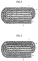
- Conceivable battery structures include not only the structure having a single electrode laminate shown in Fig. 1 which is composed of a couple of electrodes stuck to a separator but multilayer structures, such as a tabular laminate structure shown in Fig. 2 which is composed of a plurality of electrode laminates and tabular roll type structures shown in Figs. 3 and 4 in which an electrode laminate is rolled up into an oblong ellipsoid. Adhesive strength and high ion conductivity being thus secured, compact multilayer structure batteries having high performance and a large battery capacity can be obtained without requiring a firm battery case.
- Examples 1 to 5 and Comparative Examples 1 to 5 batteries basically having the structure illustrated in Fig. 1 were prepared, and the adhesive strength and charge and discharge characteristics of the resulting batteries were measured.
- the adhesive strength of the batteries was obtained in terms of 180° peel strength of a test specimen (20 mm x 100 mm x 0.2 mm) prepared by adhering a positive electrode 1 and a negative electrode 4 to a separator 7 with an adhesive 8. Measurement was made with UTMII-20 manufactured by Toyo Baldwin at a pulling speed of 10 mm/min at 25°C.
- Positive electrode active material paste consisting of 87 wt% of LiCoO 2 , 8 wt% of graphite powder, and 5 wt% of polyvinylidene fluoride was applied with a doctor blade to a coating thickness of 300 ⁇ m to form an active material film.
- a 30 ⁇ m thick aluminum net as a positive electrode current collector was placed thereon, and the positive electrode active material paste was again spread on the net with a doctor blade to a thickness of 300 ⁇ m.
- the double-coated aluminum net was allowed to stand in a drier kept at 60°C for 60 minutes to make the paste layers half-dried.
- the resulting laminate was lightly rolled to a thickness of 400 ⁇ m to prepare a positive electrode 1 having positive electrode active material layers 3 bonded to a positive electrode current collector 2.
- Negative electrode active material paste consisting of 95 wt% of Mesophase Microbead Carbon (a trade name, produced by Osaka Gas Co.,Ltd.) and 5 wt% of polyvinylidene fluoride was applied with a doctor blade to a thickness of 300 ⁇ m to make an active material film.
- a 20 ⁇ m thick copper net as a negative electrode current collector was placed thereon, and the negative electrode active material paste was again spread thereon with a doctor blade to a thickness of 300 ⁇ m.
- the laminate was allowed to stand in a drier at 60°C for 60 minutes to make the paste half-dried.
- the laminate was lightly rolled to a thickness of 400 ⁇ m to prepare a negative electrode 4 having negative electrode active material layers 6 bonded to a negative electrode current collector 5.
- PVDF polyvinylidene fluoride resin
- NMP N-methyl-2-pyrrolidone
- the above-prepared adhesive was applied to a porous polypropylene sheet (Cellgluard #2400, produced by Hoechest) used as a separator 7, and the above-prepared positive electrode and negative electrode were stuck thereto to give a prescribed total thickness.
- the laminate was hot pressed at 80°C for 1 hour and cut to a prescribed size.
- the above-prepared adhesive was applied to both sides of a porous polypropylene sheet (Cellgluard #2400, produced by Hoechest) used as a separator 7, and the positive electrode and the negative electrode were stuck thereto to give a prescribed total thickness.
- the laminate was hot pressed at 80°C in vacuo for 1 hour to obtain an electrode laminate.
- the electrode laminate was put into an aluminum laminate film pack and impregnated with an electrolytic solution consisting of 1 mol/l of lithium hexafluorophosphate in a 1:1 (by weight) mixed solvent of ethylene carbonate and diethyl carbonate under reduced pressure, and the pack was heat-sealed to complete a battery having a single layer structure.
- the peel adhesive strength of the adhesives as measured on adhesion test specimens prepared in Examples 1 to 5 and Comparative Examples 1 to 5 was evaluated according to the following standard.
- the batteries obtained in Examples 1 to 5 and Comparative Examples 1 to 5 were subjected to a charge and a discharge 100 times.
- the charge and discharge characteristics in the first and 100th cycles were evaluated according to the following standard. The results are also shown in Table 1.
- Examples 1 to 5 provide batteries showing great adhesive strength between the positive electrode 1 and the separator 7 and between the negative electrode 4 and the separator 7 and exhibiting excellent charge and discharge characteristics.
- Negative and positive electrodes and an adhesive were prepared in the same manner as in Example 1.
- the adhesive was applied to a side of two separators, and the negative electrode was inserted in between the coated sides of the two separators and joined together.
- the laminate was hot pressed at 80°C in vacuo for 1 hour to evaporate NMP from the adhesive thereby to bond the negative electrode between the two separators.
- the pair of the separators having the negative electrode bonded therebetween was punched to obtain a cut piece of a prescribed size.
- the adhesive was applied to one side of the cut piece, and the positive electrode, cut out to a prescribed size, was stuck thereto to form a laminate composed of the separator, the negative electrode, the separator, and the positive electrode in order.
- the adhesive was applied to a side of another laminate composed of a pair of separators and another sheet of the negative electrode sandwiched therebetween cut to a prescribed size, and the coated side was stuck to the positive electrode of the previously prepared laminate.
- the above-described steps were repeated to build up a battery body having a plurality of electrode laminates.
- the battery body was dried while applying pressure to prepare a tabular laminated battery body as shown in Fig. 2.
- a current collector tab was connected to every end of the positive electrode current collectors and the negative electrode current collectors of the resulting tabular laminated battery body, and the current collector tabs were spot welded to establish parallel electrical connections among the positive electrodes and among the negative electrodes.
- the tabular roll type laminated battery body was put into an aluminum laminate film pack and impregnated with an electrolytic solution in the same manner as in Example 1, and the pack was heat-sealed to complete a battery having a multilayer structure.
- Example 6 may be modified in such a manner that the steps of joining the positive electrode in two separators in the same manner as described above, applying the adhesive to a side of the paired separators having the positive electrode therebetween, sticking the negative electrode to the coated side of the paired separators, and sticking another paired separators having the positive electrode therebetween to the thus adhered negative electrode are repeated.
- Negative and positive electrodes and an adhesive were prepared in the same manner as in Example 1.
- the adhesive was applied to a side of two separators having a band form, and the positive electrode of band form was inserted in between the coated sides of the two separators and joined together.
- the resulting laminate was hot pressed at 80°C in vacuo for 1 hour to evaporate NMP from the adhesive thereby to bond the positive electrode between the two separators.
- the prepared adhesive was applied to one of the paired separators of band form having the positive electrode therebetween.
- One end of the paired separators was folded back at a prescribed length with the adhesive-coated side inward, the negative electrode cut to a prescribed size was inserted into the fold, and the folded laminate was passed through a laminator.
- the adhesive was applied to the other side of the paired separators of band form, and another cut piece of the negative electrode having a prescribed size was stuck thereto at the position facing the negative electrode having been inserted into the fold.
- the paired separators were rolled by a half turn in such a manner that the negative electrode thus stuck might be wrapped in, making an oblong ellipsoid.
- the separators were again rolled up with still another cut piece of the negative electrode inserted therein. These steps were repeated to form a battery body having a plurality of electrode laminates.
- the battery body was dried under pressure to obtain a tabular laminated battery body of roll form as shown in Fig. 3.
- Example 7 While in Example 7 an example in which a pair of separator bands having a positive electrode of band form joined therebetween is rolled up with a plurality of negative electrodes of prescribed size being each inserted for every half turn has been described, it is possible that a pair of separator bands having a negative electrode of band form joined therebetween is rolled up with a plurality of positive electrodes of prescribed size being each inserted for every half turn.
- Example 7 has shown a method in which the separators were rolled up, it is replaced by a method in which a pair of separator bands having a positive or negative electrode of band form joined therebetween are folded while inserting a cut piece of a negative or positive electrode into every fold.
- Negative and positive electrodes and an adhesive were prepared in the same manner as in Example 1.
- the positive electrode of band form was arranged between two separators, and the negative electrode of band form was placed on the outer side of one of the separators with a prescribed length of its starting end sticking out over the end of that separator.
- the adhesive had previously been applied to the inner side of the paired separators and the outer side of one of the separators on which the negative electrode was to be arranged.
- the sticking end of the negative electrode was first sent to a laminator, and the negative electrode, the separator, the positive electrode, and the separator were then passed through the laminator to form a laminate of band form.
- the adhesive was then applied to the outer side of the other separator, and the sticking end of the negative electrode was folded back and stuck to the adhesive-coated surface.
- the laminate was rolled up in such a manner that the folded negative electrode might be wrapped in to make an oblong ellipsoid to form a battery body having a plurality of electrode laminates as shown in Fig. 4.
- the battery body was dried under pressure to obtain a tabular roll type laminated battery body.
- the battery body was impregnated with an electrolytic solution and sealed in the same manner as in Example 1 to complete a battery.
- the positive electrode of band form was arranged between a pair of separators of band form, and the negative electrode was arranged on one of the separators
- the same type of a battery could be prepared by arranging the negative electrode of band form in between the separators of band form and the positive electrode on one of the separators, and rolling up the laminate.
- the present invention provides batteries which can have reduced size and weight and an arbitrary shape as well as improved performance and can be used in portable electronic equipment, such as portable personal computers and cellular phones.
Landscapes
- Chemical & Material Sciences (AREA)
- Chemical Kinetics & Catalysis (AREA)
- Electrochemistry (AREA)
- General Chemical & Material Sciences (AREA)
- Organic Chemistry (AREA)
- Engineering & Computer Science (AREA)
- Manufacturing & Machinery (AREA)
- Secondary Cells (AREA)
- Battery Electrode And Active Subsutance (AREA)
- Cell Separators (AREA)
Abstract
An adhesive for batteries a solution of which has improved
wetting properties, which affords improved adhesive strength and
prevents deterioration of battery performance, and which can
provide secondary batteries having an arbitrary shape, such as a
thin shape, with high reliability and high charge and discharge
efficiency, and a battery using the same are disclosed. An adhesive
comprising a thermoplastic resin, a solvent capable of dissolving
the thermoplastic resin, and a neutral and aprotic surface active
agent is used as an adhesive for batteries for adhering an active
material layer joined to a current collector to a separator, whereby
a secondary battery which can take an arbitrary shape, such as a
thin shape, with high reliability and high charge and discharge
efficiency can be obtained.
Description
This invention relates to secondary batteries used in, for
example, portable electronic equipment. More particularly, it
relates to batteries that can take an arbitrary shape, such as a
thin shape, and an adhesive used therein.
There has been an eager demand for reduction in size and
weight of portable electronic equipment, and improvement of battery
performance and battery size reduction are indispensable for the
realization. To meet the demand, development and improvement of
batteries from various aspects have been proceeding.
Characteristics required of batteries include high voltage, high
energy density, reliability, and freedom of shape design. Of
available batteries, lithium ion batteries are secondary batteries
that are the most expected to achieve a high voltage and a high energy
density and will undergo successive improvements.
A lithium ion secondary battery mainly comprises a positive
electrode, a negative electrode, and an ion conducting layer
interposed between the electrodes. The lithium ion secondary
batteries that have been put to practical use employ a positive plate
prepared by applying powder of lithium-cobalt oxide, etc. as an
active material to a current collector and a negative plate similarly
prepared by applying powder of a carbonaceous material as an active
material to a current collector, with a separator, as an ion
conducting layer, made of a porous film of polyethylene,
polypropylene, etc. and filled with a nonaqueous electrolytic
solution being interposed therebetween.
In order to maintain electrical contacts among a positive
electrode, a separator and a negative electrode, it is necessary
in a conventional lithium ion secondary battery to externally apply
pressure by means of a firm battery case made of metal, etc. to
maintain all the planar contacts as described in JP-A-8-83608.
JP-A-5-159802 discloses a solid secondary battery, in which
an ion conducting solid electrolyte layer and an electrode material
layer are heat bonded with a thermoplastic resin binder to make an
integral battery body. In this case, since the electrodes and the
electrolyte layer are united into an integral body to maintain
electrical contacts, the function as a battery is performed without
external pressure application. With reference to thin type
batteries, those using polymer gel as an ion conductor are known
as described in U.S. Patent 5,460,904. The disclosed thin type
batteries are characterized in that polyvinylidene fluoride and a
hexafluoropropene copolymer are used as polymer gel to join a
positive electrode, a separator, and a negative electrode into an
integral body.
Conventional batteries being thus constituted, a firm
battery case that imposes external pressure to the electrode layer
and the electrolyte layer must be used so as to bring them into
sufficient electrical contact. As a result, the case which does
not participate in electricity generation has a large proportion
in the total volume or weight of a battery, which is disadvantageous
for production of batteries having a high energy density.
In those batteries in which an electrode layer and a solid
electrolyte layer are joined via a binder, the electrode-electrolyte
interface is covered with a solid binder, which is
disadvantageous from the standpoint of electrical conductivity
through the electrode-electrolyte interface as compared with, for
example, the above-mentioned type of batteries in which a liquid
electrolyte is used and external pressure is applied by means of
a battery case. Where a binder is used, on the other hand, no binders
equal to a liquid electrolyte in electrical conductivity has been
developed as yet, failing to secure equality in electrical
conductivity to a battery using a liquid electrolyte.
Further, the thin type batteries using polymer gel fail to
have equality in charge and discharge characteristics to those using
a liquid electrolyte because there is no gel electrolyte generally
known to be equal or superior to a liquid electrolyte in electrical
conductivity.
The present invention has been completed in order to solve
the above-described problems. Accordingly, an object of the
invention is to provide an adhesive with which an electrode layer
and an electrolyte layer are joined to establish a satisfactory
electrical contact through the electrode-electrolyte layers
without using a firm case for external pressure application; and
to efficiently produce a thin, light and highly reliable battery
with excellent charge and discharge characteristics by using the
adhesive.
A first adhesive for batteries according to the present
invention is an adhesive for batteries used for adhering an active
material layer joined to a current collector to a separator, which
comprises a thermoplastic resin, a solvent capable of dissolving
the thermoplastic resin, and a neutral and aprotic surface active
agent. A solution of the adhesive exhibits improved wetting to
bring improved adhesive strength so that deterioration in battery
performance can be prevented, and productivity of batteries can be
improved. Accordingly, secondary batteries which can take any
arbitrary shape, such as a thin shape, secure reliability, and
exhibit high charge and discharge efficiency can be produced.
A second adhesive for batteries according to the invention
is the above-described first adhesive for batteries, in which the
surface-active agent has a polysiloxane skeleton in the molecule
thereof. In this aspect the battery performance is further improved,
and the workability is improved.
A first battery according to the invention has an electrode
laminate composed of a couple of electrodes each having an active
material layer bonded to a current collector and a separator
sandwiched therebetween and adhered to the active material layer
of each electrode with an adhesive comprising a thermoplastic resin,
a solvent capable of dissolving the thermoplastic resin, and a
neutral and aprotic surface active agent. In this aspect, practical
secondary batteries which can take any arbitrary shape, such as a
thin shape, secure reliability, and exhibit high charge and
discharge efficiency can be obtained.
A second battery according to the invention is the
above-described first battery which has a plurality of the electrode
laminates. A battery having a multilayer structure and a so
increased capacity can be obtained while being compact, securing
reliability, and exhibiting high charge and discharge efficiency.
A third battery according to the invention is the
above-described second battery, wherein the plurality of electrode
laminates are formed by interposing a positive electrode and a
negative electrode alternately among a plurality of cut sheets of
the separator.
A fourth battery according to the invention is the
above-described second battery, wherein the plurality of electrode
laminates are formed by interposing a positive electrode and a
negative electrode alternately between rolled separators.
A fifth battery according to the invention is the
above-described second battery, wherein the plurality of electrode
laminates are formed by interposing a positive electrode and a
negative electrode alternately between folded separators.
The inventors have extensively investigated on a favorable
method for adhering a separator to each active material layer of
a couple of electrodes comprising an active material layer joined
to a current collector and, as a result, reached the present
invention.
The present invention relates to an adhesive 8 used in
manufacture of batteries which comprise, as shown in Fig. 1, a
positive electrode 1 having a positive electrode active material
layer 3 adhered to a positive electrode current collector 2, a
negative electrode 4 having a negative electrode active material
layer 6 adhered to a negative electrode current collector 5, an a
separator 7 holding an electrolytic solution, the adhesive 8 being
used to join the positive electrode 1 and the negative electrode
4 to the separator 7.
The characteristic of the invention resides in the
composition of the adhesive 8 adhering the electrodes 1 and 4 to
the separator. The adhesive 8 is characterized by containing a
thermoplastic resin, a solvent capable of dissolving the
thermoplastic resin and a neutral and aprotic surface-active agent.
The inventors have conducted extensive studies on how to
reduce the thickness of a secondary battery while retaining
reliability and increasing charge and discharge efficiency. As a
result, they have found that a secondary battery that can take an
arbitrary shape, such as a thin shape, and yet secures reliability
and exhibits high charge and discharge efficiency can be obtained
by using, as an adhesive 8, a composition comprising a thermoplastic
resin, a solvent capable of dissolving the thermoplastic resin, and
a neutral and aprotic surface active agent and completed the present
invention.
According to the inventors' study, a solution comprising
a thermoplastic resin and a solvent capable of dissolving the
thermoplastic resin and having added thereto a surface active agent
has improved wetting properties and can be smoothly and uniformly
applied as an adhesive 8 on a separator. It is considered therefore
that adhesive strength enough to produce an integral battery body
is exerted even with a small content of the thermoplastic resin,
which has smaller ion conductivity than a liquid electrolyte, in
the adhesive.
The thermoplastic resins which can be used include
polyvinylidene fluoride, polyvinyl alcohol, and mixtures thereof.
Any solvent is useful for dissolving the thermoplastic
resin as far as it is capable of dissolving the thermoplastic resin.
Useful solvents include N-methyl-2-pyrrolidone, N,N-dimethylformamide,
N,N-dimethylacetamide, γ-butyrolactone, and
mixed solvents containing one or more of these compounds.
The surface-active agents which can be used are neutral and
aprotic ones. Those having a polysiloxane structure in the
molecular skeleton thereof are especially preferred for battery
performance obtained and their availability and convenience of
handling. In particular, those reactive with water, such as
polymethoxypolysiloxane, not only act as a surface active agent but
are expected to bring about improved battery characteristics and
long-term reliability because they would react with moisture which
may have been present in the members constituting the battery or
may have entered the inside of the battery after assembly to remove
the water content in the battery.
In some cases, it is possible to add fillers, such as
inorganic oxides, to the adhesive solution. In this case it is
expected that the surface-active agent contained in the adhesive
will facilitate uniform dispersion of the filler in the adhesive
solution because of its general character. The filler added will
make the adhesive layer porous, forming more voids through which
ions are conducted, so that the battery performance will be improved
further.
Any separator made of an electrically insulating material
that has sufficient strength, such as porous film, net, and nonwoven
fabric, can be used. While not limiting, a single layer or
multilayer porous film of polyethylene or polypropylene is
preferred for battery performance obtained.
Conceivable battery structures include not only the
structure having a single electrode laminate shown in Fig. 1 which
is composed of a couple of electrodes stuck to a separator but
multilayer structures, such as a tabular laminate structure shown
in Fig. 2 which is composed of a plurality of electrode laminates
and tabular roll type structures shown in Figs. 3 and 4 in which
an electrode laminate is rolled up into an oblong ellipsoid.
Adhesive strength and high ion conductivity being thus secured,
compact multilayer structure batteries having high performance and
a large battery capacity can be obtained without requiring a firm
battery case.
The present invention will now be illustrated in greater
detail with reference to Examples and Comparative Examples, but the
present invention is not deemed to be limited thereto. In Examples
1 to 5 and Comparative Examples 1 to 5 batteries basically having
the structure illustrated in Fig. 1 were prepared, and the adhesive
strength and charge and discharge characteristics of the resulting
batteries were measured.
The adhesive strength of the batteries was obtained in terms
of 180° peel strength of a test specimen (20 mm x 100 mm x 0.2 mm)
prepared by adhering a positive electrode 1 and a negative electrode
4 to a separator 7 with an adhesive 8. Measurement was made with
UTMII-20 manufactured by Toyo Baldwin at a pulling speed of 10 mm/min
at 25°C.
Charge and discharge characteristics were measured in
accordance with the method described in Denchi Binran Henshu Iinkai
(ed.), Denchi Binran, Maruzen (1990) under the following
conditions.
- Charge:
- constant current and constant voltage charge Cut-off voltage: 4.2 v
- Discharge:
- constant current discharge Cut-off voltage: 2.5 V
- Battery electrode capacity:
- 100 mAh
- Charging and discharging current:
- 100 mA
Positive electrode active material paste consisting of
87 wt% of LiCoO2, 8 wt% of graphite powder, and 5 wt% of
polyvinylidene fluoride was applied with a doctor blade to a coating
thickness of 300 µm to form an active material film. A 30 µm thick
aluminum net as a positive electrode current collector was placed
thereon, and the positive electrode active material paste was again
spread on the net with a doctor blade to a thickness of 300 µm. The
double-coated aluminum net was allowed to stand in a drier kept at
60°C for 60 minutes to make the paste layers half-dried. The
resulting laminate was lightly rolled to a thickness of 400 µm to
prepare a positive electrode 1 having positive electrode active
material layers 3 bonded to a positive electrode current collector
2.
Negative electrode active material paste consisting of
95 wt% of Mesophase Microbead Carbon (a trade name, produced by Osaka
Gas Co.,Ltd.) and 5 wt% of polyvinylidene fluoride was applied with
a doctor blade to a thickness of 300 µm to make an active material
film. A 20 µm thick copper net as a negative electrode current
collector was placed thereon, and the negative electrode active
material paste was again spread thereon with a doctor blade to a
thickness of 300 µm. The laminate was allowed to stand in a drier
at 60°C for 60 minutes to make the paste half-dried. The laminate
was lightly rolled to a thickness of 400 µm to prepare a negative
electrode 4 having negative electrode active material layers 6
bonded to a negative electrode current collector 5.
A polyvinylidene fluoride resin (hereinafter abbreviated
as PVDF) was added to N-methyl-2-pyrrolidone (hereinafter
abbreviated as NMP), and the mixture was heated to 80°C with stirring
to prepare a uniform solution. A prescribed amount of a surface
active agent described below was added to the solution, followed
by stirring to prepare an adhesive.
The above-prepared adhesive was applied to a porous
polypropylene sheet (Cellgluard #2400, produced by Hoechest) used
as a separator 7, and the above-prepared positive electrode and
negative electrode were stuck thereto to give a prescribed total
thickness. The laminate was hot pressed at 80°C for 1 hour and cut
to a prescribed size.
The above-prepared adhesive was applied to both sides of
a porous polypropylene sheet (Cellgluard #2400, produced by
Hoechest) used as a separator 7, and the positive electrode and the
negative electrode were stuck thereto to give a prescribed total
thickness. The laminate was hot pressed at 80°C in vacuo for 1 hour
to obtain an electrode laminate. The electrode laminate was put
into an aluminum laminate film pack and impregnated with an
electrolytic solution consisting of 1 mol/l of lithium
hexafluorophosphate in a 1:1 (by weight) mixed solvent of ethylene
carbonate and diethyl carbonate under reduced pressure, and the pack
was heat-sealed to complete a battery having a single layer
structure.
- Surfactant 1:
- polysiloxane-polyoxyalkylene copolymer having an HLB value of 1, used in the adhesive of the invention as a surfactant.
- Surfactant 2:
- polysiloxane-polyoxyalkylene copolymer having an HLB value of 4, used in the adhesive of the invention as a surfactant.
- Surfactant 3:
- polysiloxane-polyoxyalkylene copolymer having an HLB value of 9, used in the adhesive of the invention as a surfactant.
- Surfactant 4:
- monoperfluoroalkyl ethylphosphoric ester, used in the adhesive of the invention as a surfactant.
- Surfactant 5:
- polymethoxypolysiloxane, used in the adhesive of the invention as a surfactant.
- Surfactant 6:
- polyethylene glycol monofatty acid ester compound, which is a protic surfactant different from those used in the invention.
- Surfactant 7:
- polyoxyethylene alkylamine compound, which is a protic and basic surfactant different from those used in the invention.
The HLB value is a value indicative of the performance of
a surface active agent, which is obtained according to formula (1)
shown below as described, e.g., in Hiroshi Horiguchi, Shin-kaimen
Kasseizai, Sankyo Shuppan K.K. (1975).
HLB = 20 x (1 - (M'/M))
wherein M: molecular weight of a surface active agent; M':
molecular weight of the hydrophobic group in the surface
active agent.
| PVDF Concn. in Adhesive (wt%) | Added Surfactant | Surfactant Concn. in Adhesive (wt%) | Spread of Adhesive (mg/cm2) | Adhesive Strength | Charge and Discharge Characteristics | |||
| 1st Cycle | 100th Cycle | |||||||
| Example | 1 | 5 | | 0.5 | 3 | good | good | good |
| 2 | 5 | surfactant 2 | 0.5 | 3 | good | good | good | |
| 3 | 5 | | 0.5 | 3 | good | good | good | |
| 4 | 5 | | 0.5 | 3 | good | good | good | |
| 5 | 5 | | 0.5 | 3 | good | good | good | |
| Compara. Example | 1 | 5 | none | - | 3 | bad | bad | bad |
| 2 | 5 | none | - | 6 | good | bad | bad | |
| 3 | 10 | none | - | 3 | good | bad | bad | |
| 4 | 5 | surfactant 6 | 0.5 | 3 | good | good | bad | |
| 5 | 5 | | 0.5 | 3 | good | good | bad |
The peel adhesive strength of the adhesives as measured on
adhesion test specimens prepared in Examples 1 to 5 and Comparative
Examples 1 to 5 was evaluated according to the following standard.
The results obtained are shown in Table 1 above.
- Good
- The peel strength was 30 gf/cm or greater between
positive electrode 1 andseparator 7 and betweennegative electrode 4 andseparator 7. - Poor
- The peel strength was lower than 30 gf/cm between
positive electrode 1 andseparator 7 and/or betweennegative electrode 4 andseparator 7.
The batteries obtained in Examples 1 to 5 and Comparative
Examples 1 to 5 were subjected to a charge and a discharge 100 times.
The charge and discharge characteristics in the first and 100th
cycles were evaluated according to the following standard. The
results are also shown in Table 1.
- Good
- The charge and discharge efficiency was 70% or higher.
- Poor
- The charge and discharge efficiency was lower than 70%, or the battery was impossible to charge and discharge.
As is apparent from Table 1, Examples 1 to 5 provide
batteries showing great adhesive strength between the positive
electrode 1 and the separator 7 and between the negative electrode
4 and the separator 7 and exhibiting excellent charge and discharge
characteristics.
Where no surface active agent was added as in Comparative
Example 1, adhesive strength sufficient for joining the positive
electrode 1, the separator 7 and the negative electrode 4 into an
integral battery body was not obtained although the PVDF
concentration and the spread of the adhesive were equal to those
in Examples 1 to 5.
As shown in Comparative Example 2, where no surface active
agent was added, and the spread of the adhesive was double that in
Examples 1 to 5, sufficient adhesive strength was attained, but the
charge and discharge characteristics were deteriorated.
As shown in Comparative Example 3, where no surface active
agent was added while doubling the PVDF concentration as compared
with Examples 1 to 5, sufficient adhesive strength was attained,
but the charge and discharge characteristics were deteriorated.
Where a protic compound or a basic compound was used as a
surface active agent as in Comparative Examples 4 or 5, deterioration
in adhesive strength and charge and discharge characteristics
resulted.
Negative and positive electrodes and an adhesive were
prepared in the same manner as in Example 1. The adhesive was applied
to a side of two separators, and the negative electrode was inserted
in between the coated sides of the two separators and joined together.
The laminate was hot pressed at 80°C in vacuo for 1 hour to evaporate
NMP from the adhesive thereby to bond the negative electrode between
the two separators.
The pair of the separators having the negative electrode
bonded therebetween was punched to obtain a cut piece of a prescribed
size. The adhesive was applied to one side of the cut piece, and
the positive electrode, cut out to a prescribed size, was stuck
thereto to form a laminate composed of the separator, the negative
electrode, the separator, and the positive electrode in order. The
adhesive was applied to a side of another laminate composed of a
pair of separators and another sheet of the negative electrode
sandwiched therebetween cut to a prescribed size, and the coated
side was stuck to the positive electrode of the previously prepared
laminate. The above-described steps were repeated to build up a
battery body having a plurality of electrode laminates. The battery
body was dried while applying pressure to prepare a tabular laminated
battery body as shown in Fig. 2.
A current collector tab was connected to every end of the
positive electrode current collectors and the negative electrode
current collectors of the resulting tabular laminated battery body,
and the current collector tabs were spot welded to establish parallel
electrical connections among the positive electrodes and among the
negative electrodes. The tabular roll type laminated battery body
was put into an aluminum laminate film pack and impregnated with
an electrolytic solution in the same manner as in Example 1, and
the pack was heat-sealed to complete a battery having a multilayer
structure.
Example 6 may be modified in such a manner that the steps
of joining the positive electrode in two separators in the same
manner as described above, applying the adhesive to a side of the
paired separators having the positive electrode therebetween,
sticking the negative electrode to the coated side of the paired
separators, and sticking another paired separators having the
positive electrode therebetween to the thus adhered negative
electrode are repeated.
Negative and positive electrodes and an adhesive were
prepared in the same manner as in Example 1. The adhesive was applied
to a side of two separators having a band form, and the positive
electrode of band form was inserted in between the coated sides of
the two separators and joined together. The resulting laminate was
hot pressed at 80°C in vacuo for 1 hour to evaporate NMP from the
adhesive thereby to bond the positive electrode between the two
separators.
The prepared adhesive was applied to one of the paired
separators of band form having the positive electrode therebetween.
One end of the paired separators was folded back at a prescribed
length with the adhesive-coated side inward, the negative electrode
cut to a prescribed size was inserted into the fold, and the folded
laminate was passed through a laminator. Subsequently, the
adhesive was applied to the other side of the paired separators of
band form, and another cut piece of the negative electrode having
a prescribed size was stuck thereto at the position facing the
negative electrode having been inserted into the fold. The paired
separators were rolled by a half turn in such a manner that the
negative electrode thus stuck might be wrapped in, making an oblong
ellipsoid. The separators were again rolled up with still another
cut piece of the negative electrode inserted therein. These steps
were repeated to form a battery body having a plurality of electrode
laminates. The battery body was dried under pressure to obtain a
tabular laminated battery body of roll form as shown in Fig. 3.
Current collector tabs connected to every end of the
negative electrode current collectors of the resulting tabular roll
type laminated battery body were spot welded to establish parallel
electrical connections. The tabular roll type laminated battery
body was impregnated with an electrolytic solution and sealed in
the same manner as in Example 1 to obtain a multilayer secondary
battery.
While in Example 7 an example in which a pair of separator
bands having a positive electrode of band form joined therebetween
is rolled up with a plurality of negative electrodes of prescribed
size being each inserted for every half turn has been described,
it is possible that a pair of separator bands having a negative
electrode of band form joined therebetween is rolled up with a
plurality of positive electrodes of prescribed size being each
inserted for every half turn.
Further, while Example 7 has shown a method in which the
separators were rolled up, it is replaced by a method in which a
pair of separator bands having a positive or negative electrode of
band form joined therebetween are folded while inserting a cut piece
of a negative or positive electrode into every fold.
Negative and positive electrodes and an adhesive were
prepared in the same manner as in Example 1.
The positive electrode of band form was arranged between
two separators, and the negative electrode of band form was placed
on the outer side of one of the separators with a prescribed length
of its starting end sticking out over the end of that separator.
The adhesive had previously been applied to the inner side of the
paired separators and the outer side of one of the separators on
which the negative electrode was to be arranged. The sticking end
of the negative electrode was first sent to a laminator, and the
negative electrode, the separator, the positive electrode, and the
separator were then passed through the laminator to form a laminate
of band form. The adhesive was then applied to the outer side of
the other separator, and the sticking end of the negative electrode
was folded back and stuck to the adhesive-coated surface. The
laminate was rolled up in such a manner that the folded negative
electrode might be wrapped in to make an oblong ellipsoid to form
a battery body having a plurality of electrode laminates as shown
in Fig. 4. The battery body was dried under pressure to obtain a
tabular roll type laminated battery body. The battery body was
impregnated with an electrolytic solution and sealed in the same
manner as in Example 1 to complete a battery.
While in the above example the positive electrode of band
form was arranged between a pair of separators of band form, and
the negative electrode was arranged on one of the separators, the
same type of a battery could be prepared by arranging the negative
electrode of band form in between the separators of band form and
the positive electrode on one of the separators, and rolling up the
laminate.
In Examples 6 to 8, when the number of the electrode
laminates was varied, the battery capacity increased with the number
of the laminates.
The present invention provides batteries which can have
reduced size and weight and an arbitrary shape as well as improved
performance and can be used in portable electronic equipment, such
as portable personal computers and cellular phones.
Claims (7)
- An adhesive for batteries used for adhering an active material layer joined to a current collector to a separator, characterized by comprising a thermoplastic resin, a solvent capable of dissolving the thermoplastic resin, and a neutral and aprotic surface active agent.
- An adhesive for batteries according to claim 1, characterized in that the surface active agent has a polysiloxane skeleton in the molecule thereof.
- A battery characterized by having an electrode laminate composed of a couple of electrodes each having an active material layer bonded to a current collector and a separator which is sandwiched therebetween and adhered to the active material layer of each electrode with an adhesive comprising a thermoplastic resin, a solvent capable of dissolving the thermoplastic resin, and a neutral and aprotic surface active agent.
- A battery according to claim 3, characterized by having a plurality of the electrode laminates.
- A battery according to claim 4, characterized in that the plurality of electrode laminates are formed by interposing a positive electrode and a negative electrode alternately among a plurality of cut sheets of the separator.
- A battery according to claim 4, characterized in that the plurality of electrode laminates are formed by interposing a positive electrode and a negative electrode alternately between rolled separators.
- A battery according to claim 4, characterized in that the plurality of electrode laminates are formed by interposing a positive electrode and a negative electrode alternately between folded separators.
Applications Claiming Priority (2)
| Application Number | Priority Date | Filing Date | Title |
|---|---|---|---|
| CN97181451A CN1127773C (en) | 1997-11-19 | 1997-11-19 | Adhesive for battery and battery using same |
| PCT/JP1997/004202 WO1999026308A1 (en) | 1997-11-19 | 1997-11-19 | Bonding agent for cells and cell using the same |
Publications (2)
| Publication Number | Publication Date |
|---|---|
| EP0954043A1 true EP0954043A1 (en) | 1999-11-03 |
| EP0954043A4 EP0954043A4 (en) | 2005-01-19 |
Family
ID=25744428
Family Applications (1)
| Application Number | Title | Priority Date | Filing Date |
|---|---|---|---|
| EP97912503A Withdrawn EP0954043A4 (en) | 1997-11-19 | 1997-11-19 | BONDING AGENT FOR ACCUMULATORS, AND ACCUMULATOR EMPLOYING IT |
Country Status (3)
| Country | Link |
|---|---|
| EP (1) | EP0954043A4 (en) |
| CN (1) | CN1127773C (en) |
| WO (1) | WO1999026308A1 (en) |
Cited By (2)
| Publication number | Priority date | Publication date | Assignee | Title |
|---|---|---|---|---|
| EP2075869A1 (en) * | 2007-12-28 | 2009-07-01 | TDK Corporation | Wound-type electrochemical device, and method for manufacturing wound-type electrochemical device |
| US11929526B2 (en) | 2018-11-12 | 2024-03-12 | Fischer Eco Solutions Gmbh | Method for bonding two plates together for a fuel cell, especially gluing bipolar plates in a fuel cell |
Families Citing this family (8)
| Publication number | Priority date | Publication date | Assignee | Title |
|---|---|---|---|---|
| CN1120210C (en) * | 2000-06-08 | 2003-09-03 | 华南理工大学 | Adhesive for lithium ion cell |
| KR20030005759A (en) * | 2001-07-10 | 2003-01-23 | 한국전지주식회사 | Electrode for lead storage battery and method for manufacturing thereof |
| JP2008262785A (en) * | 2007-04-11 | 2008-10-30 | Matsushita Electric Ind Co Ltd | Nonaqueous electrolyte secondary battery |
| JP5132614B2 (en) * | 2009-03-16 | 2013-01-30 | 京セラ株式会社 | Lithium battery |
| JP5132613B2 (en) * | 2009-03-16 | 2013-01-30 | 京セラ株式会社 | Lithium battery |
| CN109742402A (en) * | 2019-01-08 | 2019-05-10 | 福建师范大学 | A kind of preparation method of reinforced polyvinylidene fluoride lithium battery conductive binder |
| CN112687836B (en) * | 2020-12-25 | 2022-09-06 | 惠州亿纬锂能股份有限公司 | Coating method for lithium battery pole piece |
| CN113013375A (en) * | 2021-03-01 | 2021-06-22 | 浙江谷神能源科技股份有限公司 | Coating process of thick film lithium battery and thick film lithium battery |
Family Cites Families (11)
| Publication number | Priority date | Publication date | Assignee | Title |
|---|---|---|---|---|
| JPS58120680A (en) * | 1982-01-12 | 1983-07-18 | Daicel Chem Ind Ltd | High-speed adhesive for paper |
| EP0191248A1 (en) * | 1985-01-11 | 1986-08-20 | E.I. Du Pont De Nemours And Company | Improved coated electrodes for use in electrochemical reactions |
| JPS628471A (en) * | 1985-07-04 | 1987-01-16 | Matsushita Electric Ind Co Ltd | Air button cell |
| JPH02253569A (en) * | 1989-03-27 | 1990-10-12 | Matsushita Electric Ind Co Ltd | Manufacture of solid state secondary battery |
| JPH0435351U (en) * | 1990-07-23 | 1992-03-24 | ||
| JP3361562B2 (en) * | 1993-02-25 | 2003-01-07 | ティーディーケイ株式会社 | Stacked battery |
| US5460904A (en) * | 1993-08-23 | 1995-10-24 | Bell Communications Research, Inc. | Electrolyte activatable lithium-ion rechargeable battery cell |
| US5240790A (en) * | 1993-03-10 | 1993-08-31 | Alliant Techsystems Inc. | Lithium-based polymer electrolyte electrochemical cell |
| JPH06310126A (en) * | 1993-04-23 | 1994-11-04 | Japan Storage Battery Co Ltd | Nonaquous electrolytic secondary battery |
| JP3416265B2 (en) * | 1994-05-20 | 2003-06-16 | 三洋電機株式会社 | Solid electrolyte secondary battery |
| JP3225864B2 (en) * | 1996-12-04 | 2001-11-05 | 三菱電機株式会社 | Lithium ion secondary battery and method of manufacturing the same |
-
1997
- 1997-11-19 WO PCT/JP1997/004202 patent/WO1999026308A1/en not_active Ceased
- 1997-11-19 EP EP97912503A patent/EP0954043A4/en not_active Withdrawn
- 1997-11-19 CN CN97181451A patent/CN1127773C/en not_active Expired - Fee Related
Cited By (2)
| Publication number | Priority date | Publication date | Assignee | Title |
|---|---|---|---|---|
| EP2075869A1 (en) * | 2007-12-28 | 2009-07-01 | TDK Corporation | Wound-type electrochemical device, and method for manufacturing wound-type electrochemical device |
| US11929526B2 (en) | 2018-11-12 | 2024-03-12 | Fischer Eco Solutions Gmbh | Method for bonding two plates together for a fuel cell, especially gluing bipolar plates in a fuel cell |
Also Published As
| Publication number | Publication date |
|---|---|
| EP0954043A4 (en) | 2005-01-19 |
| CN1244953A (en) | 2000-02-16 |
| WO1999026308A1 (en) | 1999-05-27 |
| CN1127773C (en) | 2003-11-12 |
Similar Documents
| Publication | Publication Date | Title |
|---|---|---|
| US6225010B1 (en) | Lithium ion secondary battery and manufacture thereof | |
| US6444355B1 (en) | Adhesive for battery, battery using the same and method of fabricating the same | |
| JP3997573B2 (en) | Lithium ion secondary battery and manufacturing method thereof | |
| US6291102B1 (en) | Lithium ion secondary battery | |
| EP0954042B1 (en) | Lithium ion secondary battery and manufacture thereof | |
| US6338920B1 (en) | Electrode for lithium ion secondary battery and lithium ion secondary battery using the same | |
| EP0859417A2 (en) | Adhesive for battery, battery using the same and method of fabricating a battery using the same | |
| US6472105B2 (en) | Bonding agent for cells and cell using the same | |
| EP0954043A1 (en) | Bonding agent for cells and cell using the same | |
| JP2005317468A (en) | Bipolar electrode, bipolar electrode manufacturing method, bipolar battery, battery pack, and vehicle equipped with the same | |
| US6537705B1 (en) | Lithium ion secondary battery and its manufacture | |
| WO1999031750A1 (en) | Adhesive for cells, a cell using the same and a process for producing cells | |
| EP0973222A1 (en) | Method for manufacturing lithium ion battery | |
| JP2004335302A (en) | Method for producing polymer battery and electrode for polymer battery | |
| US20010009736A1 (en) | Lithium ion secondary battery and process for producing the same | |
| KR100300534B1 (en) | Bonding agent for cells and cell using the same | |
| CN1245592A (en) | Lithium ion secondary battery and its manufacture | |
| CN1237651C (en) | Lithium ion secondary battery | |
| KR100301995B1 (en) | Lithium ion secondary battery and its manufacture | |
| JP2025187315A (en) | Stacked lithium-ion secondary battery, tape shear adhesive strength measurement method | |
| JPWO1999026308A1 (en) | Battery adhesive and battery using same | |
| JP2001332241A (en) | Thin battery | |
| JPWO1999031746A1 (en) | Electrode for non-aqueous battery and battery using same | |
| JPWO1999031750A1 (en) | Battery adhesive, battery using same, and battery manufacturing method | |
| JPWO1999033136A1 (en) | Lithium-ion secondary battery and its manufacturing method |
Legal Events
| Date | Code | Title | Description |
|---|---|---|---|
| PUAI | Public reference made under article 153(3) epc to a published international application that has entered the european phase |
Free format text: ORIGINAL CODE: 0009012 |
|
| 17P | Request for examination filed |
Effective date: 19990716 |
|
| AK | Designated contracting states |
Kind code of ref document: A1 Designated state(s): DE FR GB |
|
| A4 | Supplementary search report drawn up and despatched |
Effective date: 20041208 |
|
| STAA | Information on the status of an ep patent application or granted ep patent |
Free format text: STATUS: THE APPLICATION HAS BEEN WITHDRAWN |
|
| 18W | Application withdrawn |
Effective date: 20050223 |