EP0953823A2 - Capteurs de vitesse de lacets microméchaniques - Google Patents
Capteurs de vitesse de lacets microméchaniques Download PDFInfo
- Publication number
- EP0953823A2 EP0953823A2 EP19990300043 EP99300043A EP0953823A2 EP 0953823 A2 EP0953823 A2 EP 0953823A2 EP 19990300043 EP19990300043 EP 19990300043 EP 99300043 A EP99300043 A EP 99300043A EP 0953823 A2 EP0953823 A2 EP 0953823A2
- Authority
- EP
- European Patent Office
- Prior art keywords
- yaw rate
- micro
- suspension
- resonance
- driving
- Prior art date
- Legal status (The legal status is an assumption and is not a legal conclusion. Google has not performed a legal analysis and makes no representation as to the accuracy of the status listed.)
- Withdrawn
Links
Images


Classifications
-
- G—PHYSICS
- G01—MEASURING; TESTING
- G01C—MEASURING DISTANCES, LEVELS OR BEARINGS; SURVEYING; NAVIGATION; GYROSCOPIC INSTRUMENTS; PHOTOGRAMMETRY OR VIDEOGRAMMETRY
- G01C19/00—Gyroscopes; Turn-sensitive devices using vibrating masses; Turn-sensitive devices without moving masses; Measuring angular rate using gyroscopic effects
- G01C19/56—Turn-sensitive devices using vibrating masses, e.g. vibratory angular rate sensors based on Coriolis forces
- G01C19/5719—Turn-sensitive devices using vibrating masses, e.g. vibratory angular rate sensors based on Coriolis forces using planar vibrating masses driven in a translation vibration along an axis
Definitions
- This invention relates to micro yaw rate sensors suitable for measuring yaw rate around its sensing axis. More particularly, to micro yaw rate sensors fabricated with Z cut quartz wafer.
- a micro yaw rate sensor which is also called micro gyro, micro gyroscope or micro vibrating angular rate sensor, is a micromachined resonator with resonance sensing capability.
- the operation principle of the sensor follows.
- a linear momentum is created by an alternate driving force which excites the resonator in an oscillation. This resonance will be called driving resonance.
- Conservation of linear momentum implies that the vibration is restricted to the driving resonance plane defined by driving force. However, this plane is altered when the sensor is rotated around an axis parallel to the plane but perpendicular to the movement of the resonator. The original vibration, which resists this change, compensates this change by initiating a vibration out of the driving resonance plane.
- This second vibration which is induced by the so called Coriolis force, is proportional to the speed of rotation in the direction perpendicular to both the driving resonance plane and the axis of rotation.
- This secondary resonance which will be called the sensing resonance, can be detected by electric means and is indicative of rotational speed, namely, the yaw rate.
- micro yaw rate sensors Although many micro yaw rate sensors have been invented to date, none of them has been developed into a successful mass produced commercial product yet. With a review of the prior arts, it is apparent to those skilled in the art that most of the micro yaw rate sensors invented so far, has one or more disadvantages associated therewith, including: (a) sophisticated structure, (b) sophisticated frequency tuning and signal processing circuits, (c) expansive packaging, (d) low long term stability and reliability material, (e) high cost fabrication equipment, (f) high overall manufacturing cost.
- micro yaw rate sensors having the following characteristics: (a) simple structure, (b) simple driving/sensing circuitry, (c) easy to package, (d) high long term stability and reliability, (e) easy to fabricate, (f) low manufacturing cost.
- the present invention provides a micro yaw rate sensor for measuring a yaw rate about its sensing axis.
- the sensor comprises, at least, (a) a base made of a Z cut quartz wafer; (b) a proof mass; (c) two sets of suspensions, namely, a first suspension and a second suspension, supporting said proof mass from two sides and connecting said proof mass to said base; (d) a plural number of driving electrodes patterned on said first suspension; (e) a plural number of sensing electrodes patterned on said second suspension.
- Said proof mass, said suspensions, and said electrodes together form an electrically excitable resonator, fabricated from/on said base wafer by micromachining technique.
- the senor of present invention uses a resonator made of a monocrystalline Z cut quartz wafer.
- the simple structure of the sensor results from unique designs of the driving and sensing electrodes, and it can work with a simple signal processing circuit, and is highly suitable for low cost mass production by micromachining.
- Quartz belongs to the trigonal trapezohedral class (32) of the rhombohedral subsystem.
- the lattice type is hexagonal. This class is characterized by one axis of three-fold symmetry and three polar axes of two-fold symmetry perpendicular thereto and separated by angles of 120 degree. There is no center of symmetry and no plane of symmetry.
- the axes of reference (X, Y, Z) are chosen such that X is one of the axes of two-fold symmetry and Z is the axis of three-fold symmetry. Hence, cuffing a crystal at different planes will result in wafers with various different properties.
- One of the most widely used wafers is that which is cut out of a quartz crystal at the X-Y plane perpendicular to the Z axis, and is commonly called the Z cut wafer.
- a property of quartz that has found an important application in the present invention is piezoelectricity.
- the piezoelectric effect comes from an atomic dipole structure of the quartz.
- the value of the polarizing effect of each dipole is proportional to the local stress at the dipole.
- This dipole describes the local piezoelectric behavior of the quartz at each atomic unit cell level well, but the global behavior is better described by the resulting charge distribution. That is, the dipoles within the material can be fully or partially neutralized by neighboring dipoles, while the dipoles at the boundaries cannot be neutralized in the same way.
- the consequent charge distributions are shown in figure 1 where a rectangular cross-sectioned beam extending in the Y direction fabricated out of a Z-cut quartz wafer, which is called a Y beam, is under three different loads.
- the piezoelectric charge build-up due to external force on the Y beam can be read out through six simple thin wire electrodes shown in figure 2.
- the electrodes can be used to impose an electric field on the quartz to produce a piezoelectric force within the beam, equivalent of an external force.
- short circuiting symmetrical electrodes in both sides that is connecting electrodes 1 to 4, 2 to 5 and 3 to 6, then grounding electrode 2 while imposing an electric potential on electrodes 1 and 3 can create a bending force within the beam. The tip of the beam, under this bending force, is bent over to the X direction.
- this simple cantilever beam the Y quartz beam
- V z V 1 -V 4
- 2V x (V 2 -V 3 )+(V 4 -V 5 )
- subscript x, y and z indicate the direction of the strain while the numerals indicate the number of the sensing electrodes.
- a simplified sensor structure of the present invention is a resonator micromachined on a quartz wafer shown in figure 3. It has a proof mass and two suspension beams.
- This simple resonator is symmetric in the x, the y, and the z direction of quartz crystal.
- Three thin wire driving electrodes are double side patterned along the edges and the centerlines of each beam. When an alternating voltage is applied to the driving electrodes, it piezoelectrically excites a driving resonance within the wafer plane. Now rotating the sensor around the Y axis, the Coriolis force would occur and will induce a sensing resonance at the same frequency as the driving resonance but in the direction perpendicular to the wafer plane.
- the out of plane movement of the proof mass reaches its maximum value when the driving resonance reaches its maximum speed at its neutral point.
- the movement of the proof mass which is a combined effect of driving force and Coriolis force is an ellipse.
- the horizontal axis of the ellipse is in proportion to the driving force while the vertical axis is in proportion to the yaw rate.
- the piezoelectric signals corresponding to the sensing resonance induced by Coriolis force are used to detect the yaw rate.
- FIG. 4 One exemplary circuit block diagram is shown in figure 4.
- Typical electric signals flowing through the circuits are as follows.
- a signal amplifier module connected to the sensing electrodes picks up the piezoelectric charge signals induced by both driving and sensing resonance and convert it to voltage output.
- the Vs is a driving-frequency ⁇ modulated signal, and its envelope, which can be obtained through a demodulator, is in proportion to ⁇ , the yaw rate to be detected.
- a demodulator module separating the modulated low frequency signal ⁇ from high frequency modulating signal k d V 0 cos( ⁇ t) is all it needed to readout the yaw rate.
- the sensitivity of the sensor to yaw rate to be detected increases with (a) the Q factor of the sensing resonance, (b) the product of the amplitude and frequency of the driving resonance. While the dynamics of the sensor response to a change in yaw rate increases with the frequency of the resonance.
- the present invention provides micro yaw rate sensors designed with unique thin wire driving and sensing electrodes fabricated on top and bottom surfaces of a Z cut monocrystalline quartz wafer, and it differs with all micro sensors of the prior art in driving and sensing principles as well as in resonator structure.
- These sensors have the following advantages: (a) a simple structure; (b) easy to fabricate with commonly available micromachining equipment; (c) operatable at wide temperature range with good temperature stability; (d) a linear response; (e) easy to process output signal; (f) easy to package; (g) good long term stability; (h) easy to adjust sensitivity and dynamic range with dimensional change of the proof mass.
- the sensor structure are suitable for mass production with micro-machining equipment commonly available in the semiconductor industry.
- On the top and bottom surfaces of the first suspension there are driving electrodes, and on the second suspension there are sensing electrodes.
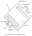
- a first embodiment of a micro yaw rate sensor made in accordance with the principle of the present invention, and generally designated by the numeral 1.
- the base 10 of the sensor 1 is a Z cut monocrystalline quartz wafer.
- the first suspension 14 and the second suspension 16 are identical Y beams with a rectangular cross section.
- the proof mass and two suspensions together form a sensor resonator with sensing axis parallel to the Y axis of the crystal.
- the driving electrodes of the sensor are a pair of thin wires double side patterned, along the edges and centerlines, on the first suspension beam.
- the driving electrodes are laid out in a serpentine manner to bend the beam with higher efficiency.
- the sensing electrodes are two single electrodes double side patterned, along the edges, on the second suspension beam. In this embodiment, all thin electrodes have a large square electric contact pad on the base wafer for ease of electric wire connections in the packaging process.
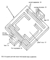
- Fig. 6 shows a second embodiment of a micro yaw rate sensor, the sensor 2, made in accordance with the principles of the present invention.
- the number of suspension beams have been doubled in this embodiment to increase the efficiency of the driving force as well as to increase the sensitivity to the Coriolis force.
- the driving electrodes are a pair of thin wires double side patterned on the first suspension beam.
- the length of the electrodes have been extended to cover the extra beam of the suspension.
- the serpentine shape electrodes are designed to create two opposite bending moments at different sections of the beam along longitudinal direction.
- the extra sensing electrodes provide additional information for functional enhancement of the sensor, such as close loop driving resonance control, acceleration detection and cancellation, etc.
- each sensor chip varies from hundreds of microns to thousands of microns, and the wafer thickness ranges from tens of microns to hundreds of microns. Generally, smaller sensors tend to be better in dynamics but large sensors tend to be higher in sensitivity.
- the above process is usually performed on both sides of the wafer simultaneously for manufacturing efficiency. And it should be apparent to those who are familiar with the arts that the sensors of present invention can be batch fabricated with very simple processes, and can be mass-produced more inexpensively in comparison with micro yaw rate sensors of the prior art.
- the sensor of present invention uses the same quartz wafer as some of the tuning fork type yaw rate sensors of the prior art, they are totally different in resonator structure and have two significant difference in design principles.
- the tuning fork type is designed with surface electrodes, which cover two of the four surfaces of a rectangular beam, including side wall surfaces.
- the surface electrodes may produce stronger driving forces than the thin wire electrodes used in present invention do, but the side wall electrodes cannot be fabricated with commonly used micromachining equipment at low cost, and have less dimensional accuracy.
- the tuning fork type sensors of the prior art require two tine resonators vibrating in opposite direction, while the sensor of present invention can operate with only one resonator which reduces sophistication in fabrication and signal processing circuitry and further lowers the cost of the sensor significantly.
- the sensor of the present invention uses a separate proof mass which can be used to adjust the dynamics of the resonator and subsequently the sensitivity and the dynamic range of the sensors.
- the tuning fork type sensors of the prior art use tines as both suspension and proof mass, so the dynamics of the tuning fork is decided by the length of the tine and the thickness of the wafer.
- the sensors of the tuning forks allow a designer only a limited range to adjust its sensitivity and dynamic range.
- the packaging and mounting of sensors of the present invention has little effect on the resonator performance while the mounting of the tuning fork type sensors often is very critical to their performance, and requires frequently patented special mounting techniques.
- the sensors can be modified by:
- the driving and sensing circuits for the sensors of the present invention should be modularized and integrated on a single chip for ease of use.
- the sensor chip, or the base wafer can be directly mounted on a printed circuit board or a plastic package to lower the cost. Alternatively, it may be packaged in an vacuum package to increase the sensitivity and to lower thermal noise.
- the present invention provides micro yaw rate sensors which have the following desirable characteristics: (a) a simple structure; (b) easy to fabricate with common micromachining equipment; (c) operatable at wide temperature range with good temperature stability; (d) a linear response; (e) easy to process readout signal; (f) easy to package; (g) good long term stability; (h) easy to adjust sensitivity and dynamic range with dimensional change without change quartz wafer and fabrication equipment.
- the sensor structure are suitable for fabrication with micro-machining techniques commonly used in the semiconductor industry, and they are inexpensive to manufacture.
Landscapes
- Physics & Mathematics (AREA)
- Engineering & Computer Science (AREA)
- General Physics & Mathematics (AREA)
- Radar, Positioning & Navigation (AREA)
- Remote Sensing (AREA)
- Gyroscopes (AREA)
- Micromachines (AREA)
Applications Claiming Priority (2)
| Application Number | Priority Date | Filing Date | Title |
|---|---|---|---|
| US8843798A | 1998-05-01 | 1998-05-01 | |
| US88437 | 1998-05-01 |
Publications (1)
| Publication Number | Publication Date |
|---|---|
| EP0953823A2 true EP0953823A2 (fr) | 1999-11-03 |
Family
ID=22211373
Family Applications (1)
| Application Number | Title | Priority Date | Filing Date |
|---|---|---|---|
| EP19990300043 Withdrawn EP0953823A2 (fr) | 1998-05-01 | 1999-01-05 | Capteurs de vitesse de lacets microméchaniques |
Country Status (2)
| Country | Link |
|---|---|
| EP (1) | EP0953823A2 (fr) |
| JP (1) | JP2000046562A (fr) |
Cited By (2)
| Publication number | Priority date | Publication date | Assignee | Title |
|---|---|---|---|---|
| US8470333B2 (en) | 2005-06-15 | 2013-06-25 | The Ohio State University Research Foundation | Chimeric peptides comprising HER-2 B-cell epitopes and T-helper epitopes |
| US9504738B2 (en) | 2009-02-04 | 2016-11-29 | Ohio State Innovation Foundation | Immunogenic epitopes, peptidomimetics, and anti-peptide antibodies, and methods of their use |
Families Citing this family (1)
| Publication number | Priority date | Publication date | Assignee | Title |
|---|---|---|---|---|
| DE102006046772A1 (de) * | 2006-09-29 | 2008-04-03 | Siemens Ag | Anordnung zur Messung einer Drehrate mit einem Vibrationssensor |
-
1999
- 1999-01-05 EP EP19990300043 patent/EP0953823A2/fr not_active Withdrawn
- 1999-02-18 JP JP11039431A patent/JP2000046562A/ja active Pending
Cited By (2)
| Publication number | Priority date | Publication date | Assignee | Title |
|---|---|---|---|---|
| US8470333B2 (en) | 2005-06-15 | 2013-06-25 | The Ohio State University Research Foundation | Chimeric peptides comprising HER-2 B-cell epitopes and T-helper epitopes |
| US9504738B2 (en) | 2009-02-04 | 2016-11-29 | Ohio State Innovation Foundation | Immunogenic epitopes, peptidomimetics, and anti-peptide antibodies, and methods of their use |
Also Published As
| Publication number | Publication date |
|---|---|
| JP2000046562A (ja) | 2000-02-18 |
Similar Documents
| Publication | Publication Date | Title |
|---|---|---|
| US20020066317A1 (en) | Micro yaw rate sensors | |
| US4750364A (en) | Angular velocity and acceleration sensor | |
| US5780740A (en) | Vibratory structure, method for controlling natural frequency thereof, and actuator, sensor, accelerator, gyroscope and gyroscope natural frequency controlling method using vibratory structure | |
| EP0604519B1 (fr) | Capteur de vitesse angulaire a diapason du type micromecanique | |
| US6470747B1 (en) | Dynamical quantity sensor | |
| US4598585A (en) | Planar inertial sensor | |
| US5691471A (en) | Acceleration and angular velocity detector | |
| JP4577671B2 (ja) | 角速度測定のための構成 | |
| US6089088A (en) | Vibrating microgyrometer | |
| US7188525B2 (en) | Angular velocity sensor | |
| WO1999019734A2 (fr) | Dispositif micro-gyroscopique a plusieurs elements | |
| EP0574143B1 (fr) | Capteur de vitesse angulaire et procédé pour sa production | |
| US6578420B1 (en) | Multi-axis micro gyro structure | |
| US10823569B1 (en) | Multiple axis sensing device based on frequency modulation and method of operation | |
| CN102119318A (zh) | 微机电系统 | |
| US7308827B2 (en) | Integrated gyroscope and temperature sensor | |
| JP2001194153A (ja) | 角速度センサ、加速度センサおよび製造方法 | |
| JPH06123632A (ja) | 力学量センサ | |
| JP2000074673A (ja) | 複合運動センサ | |
| EP0953823A2 (fr) | Capteurs de vitesse de lacets microméchaniques | |
| CA2145543C (fr) | Capteur de rotation a ondes progressives utilisant une couche mince ferroelectrique | |
| JP3931405B2 (ja) | 角速度センサ | |
| JPH08292207A (ja) | 力センサー | |
| WO2002001231A1 (fr) | Structure de gyroscope multi-axe | |
| JP2000088579A (ja) | 角速度センサとその製造方法 |
Legal Events
| Date | Code | Title | Description |
|---|---|---|---|
| PUAI | Public reference made under article 153(3) epc to a published international application that has entered the european phase |
Free format text: ORIGINAL CODE: 0009012 |
|
| AK | Designated contracting states |
Kind code of ref document: A2 Designated state(s): AT BE CH CY DE DK ES FI FR GB GR IE IT LI LU MC NL PT SE |
|
| AX | Request for extension of the european patent |
Free format text: AL;LT;LV;MK;RO;SI |
|
| STAA | Information on the status of an ep patent application or granted ep patent |
Free format text: STATUS: THE APPLICATION HAS BEEN WITHDRAWN |
|
| 18W | Application withdrawn |
Withdrawal date: 20010111 |