EP0953518B1 - Müllsammelbehälter zur getrennten Sammlung von Müll - Google Patents
Müllsammelbehälter zur getrennten Sammlung von Müll Download PDFInfo
- Publication number
- EP0953518B1 EP0953518B1 EP98830254A EP98830254A EP0953518B1 EP 0953518 B1 EP0953518 B1 EP 0953518B1 EP 98830254 A EP98830254 A EP 98830254A EP 98830254 A EP98830254 A EP 98830254A EP 0953518 B1 EP0953518 B1 EP 0953518B1
- Authority
- EP
- European Patent Office
- Prior art keywords
- dividing baffle
- container
- deflector element
- container according
- holding chamber
- Prior art date
- Legal status (The legal status is an assumption and is not a legal conclusion. Google has not performed a legal analysis and makes no representation as to the accuracy of the status listed.)
- Expired - Lifetime
Links
Images


Classifications
-
- B—PERFORMING OPERATIONS; TRANSPORTING
- B65—CONVEYING; PACKING; STORING; HANDLING THIN OR FILAMENTARY MATERIAL
- B65F—GATHERING OR REMOVAL OF DOMESTIC OR LIKE REFUSE
- B65F1/00—Refuse receptacles; Accessories therefor
- B65F1/0033—Refuse receptacles; Accessories therefor specially adapted for segregated refuse collecting, e.g. receptacles with several compartments; Combination of receptacles
- B65F1/004—Refuse receptacles; Accessories therefor specially adapted for segregated refuse collecting, e.g. receptacles with several compartments; Combination of receptacles the receptacles being divided in compartments by partitions
Definitions
- the present invention relates to a container for collecting rubbish in a differentiated manner of the kind comprising the characteristics expressed in the preamble of Claim 1.
- Each container is able to be periodically emptied by a vehicle employed for the collection and transport of the waste into tips and/or treatment centres.
- a vehicle employed for the collection and transport of the waste into tips and/or treatment centres.
- the need to use one container for each type of waste to be collected leads to the requirement to employ urban areas of considerable size, as well as additional problems in logistical terms for the management of the work shifts and of the times required to empty the containers on the vehicles.
- a main closure element of the container is opened, whilst an auxiliary closure element shuts off one of the two chambers.
- an auxiliary closure element shuts off one of the two chambers.
- only one type of waste is discharged into the hopper, to be transferred into one of the holding chamber spaces of the vehicle.
- the auxiliary closure element is opened as well, and the second type of waste is consequently deposited into the hopper and then transferred and conveyed into the respective holding chamber space.
- the object of the present invention is essentially to solve the problems noted in the prior art, proposing a rubbish container that guarantees the simultaneous discharge of waste from different chambers without mixing the waste.
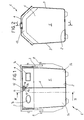
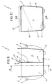
- the number 1 indicates in its entirety a container for collecting rubbish in a differentiated manner according to the present invention.
- the container 1 comprises at least one base wall 2, at least one side wall 3 rising from the perimeter of the base wall 2 and at least one closure element 4 engaged to the side wall 3 to form therewith and with the base wall 2 at least one holding space 5.
- the container 1 internally presents at least one dividing baffle 6 which subdivides the holding chamber space 5 into at least one holding chamber 5a and at least a second holding chamber 5b destined respectively to receive a first type of waste, for instance paper, and a second type of waste, for instance glass.
- the first and the second type of waste can be inserted through respective insertion openings 7a, 7b provided on the closure element 4, possibly shaped differently from each other and connected respectively to the first and to the second holding chamber 5a, 5b.
- grip means comprising for instance grip pins 8 aligned along the longitudinal centreline of the container 1, able to be engaged in a known manner by a lifting and upsetting apparatus (not shown) to empty the waste from the container 1.
- the emptying operation entails parking a vehicle alongside the container 1 whereupon, by means of the aforesaid lifting apparatus interacting with the grip pins 8, the container itself is upset above a hopper 9 or other collecting element provided on the vehicle itself.
- the hopper 9 is subdivided, by means of an internal bulkhead 10, into at least a first and a second chamber 9a, 9b which are able to receive respectively the first type of waste and the second type of waste contained in the container 1.
- this common flow zone 11 inevitably causes a part of the first type of waste to be placed into the second hopper chamber 9b, and a part of the second type of waste to be placed into the first hopper chamber 9a.
- the situation just described is avoided providing in proximity to a terminal edge 12 of the dividing baffle 6, at least one deflector element 13 able to route away from a median plane 14 of the dividing baffle, the waste exiting at least one of said first and second holding chamber 5a, 5b.
- the deflector element 13 routes the first type of waste into the respective first chamber 9a of the hopper 9, and the second type of waste into the second chamber 9b of the hopper 9.
- the deflector element 13 comprises at least a first and a second deviating surfaces 13a, 13b extending from laterally opposite sides with respect to the dividing baffle 6 mutually diverging towards the outside of the holding chamber space 5, and facing respectively towards the first holding chamber 5a and towards the second holding chamber 5b of the container 1.
- the first and the second deviating surface 13a, 13b are respectively obtained on at least a first section bar 15 and at least a second section bar 16, preferably made of elastomeric material positioned, symmetrically or asymmetrically, on respectively opposite faces of the dividing baffle 6 to define said deflector element 13.
- Each section bar 15, 16 presents a cross section profile shaped as a right triangle wherein the respective deviating surface 13a, 13b corresponds to the hypotenuse.
- the section bars 15, 16 can be fastened on the dividing baffle 6 for instance by means of rivets or other fixing means 17.
- the deflector element 13 comprises a section bar 18 made of elastomeric material, presenting triangular cross section and having, in correspondence with one of its vertices, at least one insertion groove 19 to receive in engagement the dividing baffle 6.
- first and the second deviating surfaces 13a, 13b are defined by the sides of the aforementioned elastomeric section bar 18 developing from the insertion groove 19 outward.
- the deflector element 13 comprises a section bar 20 made of elastomeric material presenting a connecting portion 21 presenting an insertion groove set to receive in engagement the terminal edge 12 of the dividing baffle 6. From the connecting portion 21 extend, from the side opposite to the insertion groove 19, at least a first and a second routing fin 22, 23 whereon are defined the deviating surfaces 13a, 13b.
- the routing fins 22, 23 extend obliquely from the connecting portion 21 towards the outside of the holding chamber space 5, to form therewith an essentially "Y" shaped profile.
- the connecting portion 21 is elastically deformable around the development of the terminal edge 12 of the dividing baffle 6, and the fins 22, 23 are elastically deformable towards and away from the median plane 14 of the dividing baffle itself.
- the fourth embodiment differs from the third in a different conformation of the profile of the connecting portion 21.
- the connecting portion presents a cross section profile with undulated configuration which further eases its flexibility around the development of the terminal edge 12 and makes the connecting portion 21 also able to be lengthened elastically away from the dividing baffle itself.
- the deflector element 13 comprises at least a first routing fin 22 joined as a single piece with the dividing baffle 6 and inclined with respect to the baffle itself.
- the deflector element 13 can further comprise a second routing fin 23 also tilted with respect to the dividing baffle 6 and rigidly engaged to the first routing fin 12 to form with the first fin 22 an essentially "V" shaped cross section profile.
- the second routing fin 13 can also be fitted in the plane 14 of the dividing baffle 6.
- the second routing fin 23 which can be constructed of metallic material, is fastened to the first routing fin 22 by means of welding, rivets or other known fixing means 17 which act on a folded portion 23a of the second routing fin 23.
- the surface of the fins 22, 23 which face towards the holding chambers 5a, 5b of the rubbish container 1 correspond to the deviating surfaces 13a, 13b acting on the falling flows 10a, 10b of the discharged waste.
- first and the second deviating surface 13a, 13b are obtained respectively on a first and on a second routing fin 22, 23, said fins converging with respect to each other to form in cross section an essentially "V" shaped profile.
- the container further comprises hinging means 24 positioned on the terminal edge 12 of the dividing baffle 6 to engage in an oscillatory manner the "V" section bar 25 defined by the routing fins 22, 23, in correspondence with its vertex or meeting point 25a between the fins themselves. In this way the "V" section bar 25 is free to rotate around the longitudinal development of the terminal edge 12 of the dividing baffle 6.
- arresting means 26 which contrast the movement of the "V" section bar 25 limiting its angle of oscillation.
- Such arresting means 26 can for instance comprise at least two arresting fins 26a, 26b obtained by notching along the terminal edge 12, as per Figure 7.
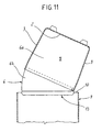
- the dividing baffle advantageously comprises a fixed portion 6a and a movable portion 6b in oscillatory engagement to the fixed portion and defining the terminal edge 12 bearing the deflector element 13, configured according to any one of the aforementioned embodiments.
- the movable portion 6b is approached parallel to the fixed portion 6a and hinged thereto, in proximity to the terminal edge 12 of the dividing baffle 6 and is thus able to be moved from a first position ( Figure 10) wherein said movable portion 6b is located within the holding chamber space 5 and a second position ( Figure 11) wherein said movable portion 6b projects at least partially from the holding chamber space 5.
- the invention fully attains the proposed objects.
- the presence of the deflector element causes the falling flows of the waste 10a, 10b during the emptying phase to be adequately deviated away from the median plane 14 of the dividing baffle 6 thereby eliminating the overlapping area of the flows 10a, 10b and any risk of mixing between waste of different kinds.
- the movable portion 6b immediately moves from the first position to the second position until it engages the deflector element 13 bearing against the terminal edge of the dividing baffle 10 provided in the hopper 9 as indicated with dashed line in Figure 13.
- the critical phase wherein the waste leaves the holding chamber space 5 travelling through a certain portion of their fall without any dividing element being interposed between the fall flow 10a, 10b is eliminated, or at least considerably reduced.
- the presence of the deflector element 13 moreover overcomes the need to collimate perfectly, during the emptying phase, the terminal edge of the dividing baffle 6 with the top edge of the bulkhead 10 of the hopper 9.
- the transverse amplitude of the deflector element 13 is such as to assure the engagement of the hopper 9 onto the dividing bulkhead 10 without requiring, for this purpose, a perfect coplanarity between the dividing baffle 6 and the baffle itself.
- deflector element 13 as shown in Figures 5, 6 and 8 offers the further advantage of easing the falling flows of the waste 10a, 10b during the emptying phase, thanks to the adaptability of the shape and/or orientation of the deflector element itself under the thrust imparted by the falling material.
- the section bars or the fins comprising the deflector element 13 can extend along the entire development of the top edge of the dividing baffle 6, or in multiple sections of predetermined length and arranged consecutively to cover the entire longitudinal development of the terminal edge itself. This latter solution is particularly well suited when the longitudinal development of the terminal edge extends along an arched and/or broken line profile, as in the example shown in Figure 2.
Claims (13)
- Müllsammelbehälter zur getrennten Sammlung von Müll, umfassend:dadurch gekennzeichnet, dass die Trennwand (6) mindestens ein Abweiselement (13) umfasst, das durch eine Endkante (12) der Trennwand (6) getragen ist, um ein Austrittsende der Trennwand (6) zu bilden, wobei das Abweiselement (13) mindestens eine erste und eine zweite Umlenkfläche (13a, 13b) umfasst, die sich von seitlich gegenüber der Trennwand (6) abgewandten Seiten erstrecken, wobei diese außerhalb des Aufnahmeraumes (5) voneinander auseinandergehen, um den aus mindestens einer der ersten und der zweiten Aufnahmekammer (5a, 5b) austretenden Müll von einer Mittelebene wegzubewegen, in der die Trennwand (6) liegt.eine Grundwand (2), mindestens eine Seitenwand (3), die sich längs des Umfanges von der Grundwand (2) erhebt, und mindestens ein Schließelement (4), das an der Seitenwand (3) in Eingriff steht, um mit dieser letzteren und der Grundwand (2) mindestens einen Aufnahmeraum (5) zu bilden;mindestens eine Trennwand (6), die innerhalb des Aufnahmeraumes (5) angeordnet ist, um in diesem letzteren eine erste Aufnahmekammer (5a) und eine zweite Aufnahmekammer (5b) festzulegen;Greifmittel (8), die durch ein Hebe- und Kippzeug wirksam erfassbar sind, um die Entleerung von Müll aus den Aufnahmekammern (5a, 5b) in ein Sammelelement zu betragen,
- Behälter nach Anspruch 1, dadurch gekennzeichnet, dass das Abweiselement (13) ein Elastomerprofil ist, an dem eine erste und eine zweite Umlenkfläche (13a, 13b) und mindestens eine Stecknut (19) vorgesehen sind, um die Trennwand (6) zu ergreifen.
- Behälter nach Anspruch 1, dadurch gekennzeichnet, dass die erste und die zweite Umlenkfläche (13a, 13b) jeweils an mindestens einem ersten Profil (15) und mindestens einem zweiten Profil (16) erhalten werden, die an jeweils abgewandten Stirnseiten der Trennwand (6) angeordnet sind, um das Abweiselement (13) festzulegen.
- Behälter nach Anspruch 1, dadurch gekennzeichnet, dass das Abweiselement (13) umfasst:mindestens einen Verbindungsabschnitt (21) der an der Trennwand (6) starr angreift;mindestens eine erste und eine zweite Ausrichtrippe (22, 23), die sich schräg vom Verbindungsabschnitt (21) nach außen des Aufnahmeraumes (15) erstrecken, um mit dem Verbindungsabschnitt (21) ein im wesentlichen "Y"-förmiges Profil zu bilden.
- Behälter nach Anspruch 4, dadurch gekennzeichnet, dass der Verbindungsabschnitt (21) mindestens um die Abwicklung der Endkante (12) der Trennwand (6) herum elastisch verformbar ist.
- Behälter nach Anspruch 5, dadurch gekennzeichnet, dass der Verbindungsabschnitt (21) ein Profil (21a) im Querschnitt gewellter Ausbildung aufweist.
- Behälter nach Anspruch 4, dadurch gekennzeichnet, dass die erste und die zweite Ausrichtrippe (22, 23) in Richtung der Mittelebene der Trennwand (6) und von derselben weg elastisch verformbar sind.
- Behälter nach Anspruch 1, dadurch gekennzeichnet, dass das Abweiselement (13) umfasst:mindestens eine erste Ausrichtrippe (21), die mit der Trennwand (6) vereint und gegenüber dieser geneigt ist;mindestens eine zweite Ausrichtrippe (23), die gegenüber der Trennwand (6) geneigt ist und mit der ersten Ausrichtrippe (22) in Eingriff steht, um mit dieser letzteren ein Profil mit im wesentlichen "V"-förmigen Querschnitt zu bilden.
- Behälter nach Anspruch 1, dadurch gekennzeichnet, dass er überdies Anlenkmittel (24) umfasst, die an der Endkante (12) der Trennwand (6) angeordnet sind, um das Abweiselement (13) schwenkbar zu ergreifen.
- Behälter nach Anspruch 9, dadurch gekennzeichnet, dass die erste und die zweite Umlenkfläche (13a, 13b) jeweils an einer ersten und an einer zweiten Ausrichtrippe (22, 23) erhalten sind, wobei die Ausrichtrippen (22, 23) zueinander zusammenlaufen, um ein Profil mit einem im wesentlichen "V"-förmigen Querschnitt bilden, mit Scheitel, der an den Anlenkmitteln (24) angreift.
- Behälter nach Anspruch 10, dadurch gekennzeichnet, dass er Rastmittel (26) umfasst, die an der Trennwand (6) angreifen, um den Schwenkwinkel des Abweiselementes (13) zu begrenzen.
- Behälter nach Anspruch 1, dadurch gekennzeichnet, dass die Trennwand (6) einen beweglichen Abschnitt (6b) umfasst, der am festliegenden Abschnitt (6a) angreift und das Abweiselement (13) trägt, wobei der bewegliche Abschnitt (6b) zwischen einer ersten Stellung, in welcher der bewegliche Abschnitt (6b) innerhalb des Aufnahmeraumes (5) liegt und einer zweiten Stellung verstellbar ist, in welcher der bewegliche Abschnitt (6b) außerhalb des Aufnahmeraumes (5) ragt.
- Behälter nach Anspruch 12, dadurch gekennzeichnet, dass der bewegliche Abschnitt (6b) an der Trennwand (6) in der Nähe der Seitenwand angelenkt ist.
Priority Applications (4)
| Application Number | Priority Date | Filing Date | Title |
|---|---|---|---|
| EP98830254A EP0953518B1 (de) | 1998-04-28 | 1998-04-28 | Müllsammelbehälter zur getrennten Sammlung von Müll |
| DE69800388T DE69800388T2 (de) | 1998-04-28 | 1998-04-28 | Müllsammelbehälter zur getrennten Sammlung von Müll |
| ES98830254T ES2144984T3 (es) | 1998-04-28 | 1998-04-28 | Un contenedor para recoger residuos de una manera diferenciada. |
| AT98830254T ATE197439T1 (de) | 1998-04-28 | 1998-04-28 | Müllsammelbehälter zur getrennten sammlung von müll |
Applications Claiming Priority (1)
| Application Number | Priority Date | Filing Date | Title |
|---|---|---|---|
| EP98830254A EP0953518B1 (de) | 1998-04-28 | 1998-04-28 | Müllsammelbehälter zur getrennten Sammlung von Müll |
Publications (2)
| Publication Number | Publication Date |
|---|---|
| EP0953518A1 EP0953518A1 (de) | 1999-11-03 |
| EP0953518B1 true EP0953518B1 (de) | 2000-11-08 |
Family
ID=8236628
Family Applications (1)
| Application Number | Title | Priority Date | Filing Date |
|---|---|---|---|
| EP98830254A Expired - Lifetime EP0953518B1 (de) | 1998-04-28 | 1998-04-28 | Müllsammelbehälter zur getrennten Sammlung von Müll |
Country Status (4)
| Country | Link |
|---|---|
| EP (1) | EP0953518B1 (de) |
| AT (1) | ATE197439T1 (de) |
| DE (1) | DE69800388T2 (de) |
| ES (1) | ES2144984T3 (de) |
Cited By (1)
| Publication number | Priority date | Publication date | Assignee | Title |
|---|---|---|---|---|
| CN109460028A (zh) * | 2018-11-23 | 2019-03-12 | 珠海格力电器股份有限公司 | 一种智能垃圾桶的控制装置及其方法与智能垃圾桶 |
Family Cites Families (6)
| Publication number | Priority date | Publication date | Assignee | Title |
|---|---|---|---|---|
| FR2582924B1 (fr) * | 1985-06-10 | 1987-08-28 | Rossignol Sa | Corbeille de bureau bivalente et appareil destine a son vidage |
| DE3703557C2 (de) * | 1987-02-06 | 1995-07-06 | Otto Lift Systeme Gmbh | Schüttung an einem Müllfahrzeug |
| DE3829076C1 (de) * | 1988-08-27 | 1989-12-28 | E.S.D. Entsorgungs-Systeme Fuer Deutschland Gmbh & Co, 8900 Augsburg, De | |
| GB9109287D0 (en) * | 1991-04-30 | 1991-06-19 | Plastic Omnium Limited | Improvements in or relating to rubbish containers |
| WO1993001111A1 (en) * | 1991-07-10 | 1993-01-21 | Colin Joseph Hickey | Collection vehicle for recyclable elements |
| WO1993020006A1 (en) * | 1992-04-01 | 1993-10-14 | Reclaimat Pty Limited | Waste processing method and device |
-
1998
- 1998-04-28 DE DE69800388T patent/DE69800388T2/de not_active Expired - Fee Related
- 1998-04-28 AT AT98830254T patent/ATE197439T1/de not_active IP Right Cessation
- 1998-04-28 ES ES98830254T patent/ES2144984T3/es not_active Expired - Lifetime
- 1998-04-28 EP EP98830254A patent/EP0953518B1/de not_active Expired - Lifetime
Cited By (1)
| Publication number | Priority date | Publication date | Assignee | Title |
|---|---|---|---|---|
| CN109460028A (zh) * | 2018-11-23 | 2019-03-12 | 珠海格力电器股份有限公司 | 一种智能垃圾桶的控制装置及其方法与智能垃圾桶 |
Also Published As
| Publication number | Publication date |
|---|---|
| DE69800388D1 (de) | 2000-12-14 |
| ES2144984T1 (es) | 2000-07-01 |
| ES2144984T3 (es) | 2001-05-16 |
| ATE197439T1 (de) | 2000-11-11 |
| EP0953518A1 (de) | 1999-11-03 |
| DE69800388T2 (de) | 2001-05-31 |
Similar Documents
| Publication | Publication Date | Title |
|---|---|---|
| US4987988A (en) | Refuse recycler | |
| US4840531A (en) | Vehicle for curbside collection of source separated recyclable materials | |
| DE59009046D1 (de) | Abfallsammelfahrzeug. | |
| DE3703557C2 (de) | Schüttung an einem Müllfahrzeug | |
| AU690268B2 (en) | Rubbish collection and transport system | |
| US6027300A (en) | Side-loading refuse vehicle | |
| EP0953518B1 (de) | Müllsammelbehälter zur getrennten Sammlung von Müll | |
| DE4121442C2 (de) | Müllsammel- und Transportsystem | |
| US5165835A (en) | Garbage disposal system | |
| CA2117025C (en) | Non-metallic polymer longitudinal hood collar | |
| US20010041127A1 (en) | Side loading waste bin | |
| WO1996039347A3 (de) | Sammelsystem für recycling-stoffe | |
| EP1820691B1 (de) | Container für ein Fahrzeug | |
| AU2008217284B2 (en) | Storage cart | |
| CZ309896A3 (en) | Marking threshold for putting onto a roadway | |
| EP0953519B1 (de) | Müllsammelbehälter zur getrennten Sammlung von Müll mit variablen Kammern zu dessen Aufbewahrung | |
| EP3313756B1 (de) | Behälter für wiederverwertbaren abfall | |
| EP0511785B1 (de) | Müllbehälter | |
| DE69903317D1 (de) | Sammel- und transportbehälter für haushaltsmüll | |
| EP0432823B1 (de) | Behälter, insbesondere ein Lackeimer | |
| CN209480794U (zh) | 一种煤渣卸料装置 | |
| EP1136389A3 (de) | Faltschachtel | |
| US6102283A (en) | Refuse discharge guide | |
| CA2142815A1 (en) | Chute for mixer discharge | |
| DE3831406A1 (de) | Muellbehaelter |
Legal Events
| Date | Code | Title | Description |
|---|---|---|---|
| PUAI | Public reference made under article 153(3) epc to a published international application that has entered the european phase |
Free format text: ORIGINAL CODE: 0009012 |
|
| 17P | Request for examination filed |
Effective date: 19981102 |
|
| AK | Designated contracting states |
Kind code of ref document: A1 Designated state(s): AT BE CH DE ES FR GB IT LI NL |
|
| AX | Request for extension of the european patent |
Free format text: AL;LT;LV;MK;RO;SI |
|
| GRAG | Despatch of communication of intention to grant |
Free format text: ORIGINAL CODE: EPIDOS AGRA |
|
| GRAG | Despatch of communication of intention to grant |
Free format text: ORIGINAL CODE: EPIDOS AGRA |
|
| GRAH | Despatch of communication of intention to grant a patent |
Free format text: ORIGINAL CODE: EPIDOS IGRA |
|
| REG | Reference to a national code |
Ref country code: ES Ref legal event code: BA2A Ref document number: 2144984 Country of ref document: ES Kind code of ref document: T1 |
|
| AKX | Designation fees paid |
Free format text: AT BE CH DE ES FR GB IT LI NL |
|
| GRAH | Despatch of communication of intention to grant a patent |
Free format text: ORIGINAL CODE: EPIDOS IGRA |
|
| GRAA | (expected) grant |
Free format text: ORIGINAL CODE: 0009210 |
|
| AK | Designated contracting states |
Kind code of ref document: B1 Designated state(s): AT BE CH DE ES FR GB IT LI NL |
|
| REF | Corresponds to: |
Ref document number: 197439 Country of ref document: AT Date of ref document: 20001111 Kind code of ref document: T |
|
| REG | Reference to a national code |
Ref country code: CH Ref legal event code: EP |
|
| REF | Corresponds to: |
Ref document number: 69800388 Country of ref document: DE Date of ref document: 20001214 |
|
| ITF | It: translation for a ep patent filed |
Owner name: BUGNION S.P.A. |
|
| REG | Reference to a national code |
Ref country code: CH Ref legal event code: NV Representative=s name: ISLER & PEDRAZZINI AG |
|
| ET | Fr: translation filed | ||
| REG | Reference to a national code |
Ref country code: ES Ref legal event code: FG2A Ref document number: 2144984 Country of ref document: ES Kind code of ref document: T3 |
|
| PLBE | No opposition filed within time limit |
Free format text: ORIGINAL CODE: 0009261 |
|
| STAA | Information on the status of an ep patent application or granted ep patent |
Free format text: STATUS: NO OPPOSITION FILED WITHIN TIME LIMIT |
|
| 26N | No opposition filed | ||
| REG | Reference to a national code |
Ref country code: GB Ref legal event code: IF02 |
|
| PGFP | Annual fee paid to national office [announced via postgrant information from national office to epo] |
Ref country code: AT Payment date: 20070323 Year of fee payment: 10 |
|
| PGFP | Annual fee paid to national office [announced via postgrant information from national office to epo] |
Ref country code: BE Payment date: 20070326 Year of fee payment: 10 |
|
| PGFP | Annual fee paid to national office [announced via postgrant information from national office to epo] |
Ref country code: DE Payment date: 20070327 Year of fee payment: 10 |
|
| PGFP | Annual fee paid to national office [announced via postgrant information from national office to epo] |
Ref country code: GB Payment date: 20070328 Year of fee payment: 10 Ref country code: CH Payment date: 20070328 Year of fee payment: 10 |
|
| PGFP | Annual fee paid to national office [announced via postgrant information from national office to epo] |
Ref country code: NL Payment date: 20070403 Year of fee payment: 10 |
|
| PGFP | Annual fee paid to national office [announced via postgrant information from national office to epo] |
Ref country code: ES Payment date: 20070416 Year of fee payment: 10 |
|
| REG | Reference to a national code |
Ref country code: CH Ref legal event code: PCAR Free format text: ISLER & PEDRAZZINI AG;POSTFACH 1772;8027 ZUERICH (CH) |
|
| PGFP | Annual fee paid to national office [announced via postgrant information from national office to epo] |
Ref country code: IT Payment date: 20070608 Year of fee payment: 10 |
|
| PGFP | Annual fee paid to national office [announced via postgrant information from national office to epo] |
Ref country code: FR Payment date: 20070426 Year of fee payment: 10 |
|
| BERE | Be: lapsed |
Owner name: *OMB BRESCIA S.P.A. Effective date: 20080430 |
|
| REG | Reference to a national code |
Ref country code: CH Ref legal event code: PL |
|
| GBPC | Gb: european patent ceased through non-payment of renewal fee |
Effective date: 20080428 |
|
| NLV4 | Nl: lapsed or anulled due to non-payment of the annual fee |
Effective date: 20081101 |
|
| PG25 | Lapsed in a contracting state [announced via postgrant information from national office to epo] |
Ref country code: NL Free format text: LAPSE BECAUSE OF NON-PAYMENT OF DUE FEES Effective date: 20081101 Ref country code: LI Free format text: LAPSE BECAUSE OF NON-PAYMENT OF DUE FEES Effective date: 20080430 Ref country code: DE Free format text: LAPSE BECAUSE OF NON-PAYMENT OF DUE FEES Effective date: 20081101 Ref country code: CH Free format text: LAPSE BECAUSE OF NON-PAYMENT OF DUE FEES Effective date: 20080430 |
|
| REG | Reference to a national code |
Ref country code: FR Ref legal event code: ST Effective date: 20081231 |
|
| PG25 | Lapsed in a contracting state [announced via postgrant information from national office to epo] |
Ref country code: AT Free format text: LAPSE BECAUSE OF NON-PAYMENT OF DUE FEES Effective date: 20080428 |
|
| PG25 | Lapsed in a contracting state [announced via postgrant information from national office to epo] |
Ref country code: BE Free format text: LAPSE BECAUSE OF NON-PAYMENT OF DUE FEES Effective date: 20080430 |
|
| PG25 | Lapsed in a contracting state [announced via postgrant information from national office to epo] |
Ref country code: FR Free format text: LAPSE BECAUSE OF NON-PAYMENT OF DUE FEES Effective date: 20080430 |
|
| REG | Reference to a national code |
Ref country code: ES Ref legal event code: FD2A Effective date: 20080429 |
|
| PG25 | Lapsed in a contracting state [announced via postgrant information from national office to epo] |
Ref country code: GB Free format text: LAPSE BECAUSE OF NON-PAYMENT OF DUE FEES Effective date: 20080428 |
|
| PG25 | Lapsed in a contracting state [announced via postgrant information from national office to epo] |
Ref country code: ES Free format text: LAPSE BECAUSE OF NON-PAYMENT OF DUE FEES Effective date: 20080429 |
|
| PG25 | Lapsed in a contracting state [announced via postgrant information from national office to epo] |
Ref country code: IT Free format text: LAPSE BECAUSE OF NON-PAYMENT OF DUE FEES Effective date: 20080428 |