EP0953064B1 - Reagent supply vessel for chemical vapor deposition - Google Patents
Reagent supply vessel for chemical vapor deposition Download PDFInfo
- Publication number
- EP0953064B1 EP0953064B1 EP97953275A EP97953275A EP0953064B1 EP 0953064 B1 EP0953064 B1 EP 0953064B1 EP 97953275 A EP97953275 A EP 97953275A EP 97953275 A EP97953275 A EP 97953275A EP 0953064 B1 EP0953064 B1 EP 0953064B1
- Authority
- EP
- European Patent Office
- Prior art keywords
- liquid
- reagent
- vessel
- tube
- liquid reagent
- Prior art date
- Legal status (The legal status is an assumption and is not a legal conclusion. Google has not performed a legal analysis and makes no representation as to the accuracy of the status listed.)
- Expired - Lifetime
Links
- 239000003153 chemical reaction reagent Substances 0.000 title claims abstract description 129
- 238000005229 chemical vapour deposition Methods 0.000 title claims description 26
- 239000007788 liquid Substances 0.000 claims abstract description 213
- 230000008021 deposition Effects 0.000 claims abstract description 7
- 238000007599 discharging Methods 0.000 claims abstract description 3
- 239000002243 precursor Substances 0.000 claims abstract description 3
- 230000008054 signal transmission Effects 0.000 claims description 23
- 238000012545 processing Methods 0.000 claims description 19
- 239000006200 vaporizer Substances 0.000 claims description 19
- 239000000758 substrate Substances 0.000 claims description 7
- 238000000151 deposition Methods 0.000 claims description 6
- KDLHZDBZIXYQEI-UHFFFAOYSA-N Palladium Chemical compound [Pd] KDLHZDBZIXYQEI-UHFFFAOYSA-N 0.000 claims description 4
- 238000004891 communication Methods 0.000 claims description 4
- BASFCYQUMIYNBI-UHFFFAOYSA-N platinum Chemical compound [Pt] BASFCYQUMIYNBI-UHFFFAOYSA-N 0.000 claims description 4
- 238000000926 separation method Methods 0.000 claims description 4
- OYPRJOBELJOOCE-UHFFFAOYSA-N Calcium Chemical compound [Ca] OYPRJOBELJOOCE-UHFFFAOYSA-N 0.000 claims description 2
- RTAQQCXQSZGOHL-UHFFFAOYSA-N Titanium Chemical compound [Ti] RTAQQCXQSZGOHL-UHFFFAOYSA-N 0.000 claims description 2
- QCWXUUIWCKQGHC-UHFFFAOYSA-N Zirconium Chemical compound [Zr] QCWXUUIWCKQGHC-UHFFFAOYSA-N 0.000 claims description 2
- 229910052787 antimony Inorganic materials 0.000 claims description 2
- WATWJIUSRGPENY-UHFFFAOYSA-N antimony atom Chemical compound [Sb] WATWJIUSRGPENY-UHFFFAOYSA-N 0.000 claims description 2
- 229910052788 barium Inorganic materials 0.000 claims description 2
- DSAJWYNOEDNPEQ-UHFFFAOYSA-N barium atom Chemical compound [Ba] DSAJWYNOEDNPEQ-UHFFFAOYSA-N 0.000 claims description 2
- 229910052797 bismuth Inorganic materials 0.000 claims description 2
- JCXGWMGPZLAOME-UHFFFAOYSA-N bismuth atom Chemical compound [Bi] JCXGWMGPZLAOME-UHFFFAOYSA-N 0.000 claims description 2
- 229910052791 calcium Inorganic materials 0.000 claims description 2
- 239000011575 calcium Substances 0.000 claims description 2
- PCHJSUWPFVWCPO-UHFFFAOYSA-N gold Chemical compound [Au] PCHJSUWPFVWCPO-UHFFFAOYSA-N 0.000 claims description 2
- 229910052737 gold Inorganic materials 0.000 claims description 2
- 239000010931 gold Substances 0.000 claims description 2
- 230000002452 interceptive effect Effects 0.000 claims description 2
- 238000005304 joining Methods 0.000 claims description 2
- 239000011133 lead Substances 0.000 claims description 2
- 229910052763 palladium Inorganic materials 0.000 claims description 2
- 229910052697 platinum Inorganic materials 0.000 claims description 2
- 229910052712 strontium Inorganic materials 0.000 claims description 2
- CIOAGBVUUVVLOB-UHFFFAOYSA-N strontium atom Chemical compound [Sr] CIOAGBVUUVVLOB-UHFFFAOYSA-N 0.000 claims description 2
- 229910052715 tantalum Inorganic materials 0.000 claims description 2
- GUVRBAGPIYLISA-UHFFFAOYSA-N tantalum atom Chemical compound [Ta] GUVRBAGPIYLISA-UHFFFAOYSA-N 0.000 claims description 2
- 229910052716 thallium Inorganic materials 0.000 claims description 2
- BKVIYDNLLOSFOA-UHFFFAOYSA-N thallium Chemical compound [Tl] BKVIYDNLLOSFOA-UHFFFAOYSA-N 0.000 claims description 2
- 229910052719 titanium Inorganic materials 0.000 claims description 2
- 239000010936 titanium Substances 0.000 claims description 2
- 229910052726 zirconium Inorganic materials 0.000 claims description 2
- 229910052751 metal Inorganic materials 0.000 claims 1
- 239000002184 metal Substances 0.000 claims 1
- 239000000463 material Substances 0.000 abstract description 15
- 238000004519 manufacturing process Methods 0.000 abstract description 7
- 239000004065 semiconductor Substances 0.000 abstract description 6
- 239000007789 gas Substances 0.000 description 37
- 238000000034 method Methods 0.000 description 10
- XKRFYHLGVUSROY-UHFFFAOYSA-N Argon Chemical compound [Ar] XKRFYHLGVUSROY-UHFFFAOYSA-N 0.000 description 4
- IJGRMHOSHXDMSA-UHFFFAOYSA-N Atomic nitrogen Chemical compound N#N IJGRMHOSHXDMSA-UHFFFAOYSA-N 0.000 description 4
- 239000002699 waste material Substances 0.000 description 4
- 238000003754 machining Methods 0.000 description 3
- 230000008016 vaporization Effects 0.000 description 3
- 238000009834 vaporization Methods 0.000 description 3
- 238000013459 approach Methods 0.000 description 2
- 229910052786 argon Inorganic materials 0.000 description 2
- 230000008901 benefit Effects 0.000 description 2
- 150000001875 compounds Chemical class 0.000 description 2
- 239000000470 constituent Substances 0.000 description 2
- 238000003801 milling Methods 0.000 description 2
- 229910052757 nitrogen Inorganic materials 0.000 description 2
- 239000002887 superconductor Substances 0.000 description 2
- 238000012360 testing method Methods 0.000 description 2
- 238000007740 vapor deposition Methods 0.000 description 2
- 230000002411 adverse Effects 0.000 description 1
- QVGXLLKOCUKJST-UHFFFAOYSA-N atomic oxygen Chemical compound [O] QVGXLLKOCUKJST-UHFFFAOYSA-N 0.000 description 1
- 238000010923 batch production Methods 0.000 description 1
- 230000005540 biological transmission Effects 0.000 description 1
- 239000012159 carrier gas Substances 0.000 description 1
- 238000005266 casting Methods 0.000 description 1
- 238000010276 construction Methods 0.000 description 1
- 230000008878 coupling Effects 0.000 description 1
- 238000010168 coupling process Methods 0.000 description 1
- 238000005859 coupling reaction Methods 0.000 description 1
- 230000002950 deficient Effects 0.000 description 1
- 238000013461 design Methods 0.000 description 1
- 238000006073 displacement reaction Methods 0.000 description 1
- 238000011143 downstream manufacturing Methods 0.000 description 1
- 238000005553 drilling Methods 0.000 description 1
- 239000003814 drug Substances 0.000 description 1
- 229940079593 drug Drugs 0.000 description 1
- 230000009977 dual effect Effects 0.000 description 1
- -1 e.g. Substances 0.000 description 1
- 238000010891 electric arc Methods 0.000 description 1
- 230000007613 environmental effect Effects 0.000 description 1
- 238000005530 etching Methods 0.000 description 1
- 239000012530 fluid Substances 0.000 description 1
- 230000004907 flux Effects 0.000 description 1
- 210000003141 lower extremity Anatomy 0.000 description 1
- 238000000465 moulding Methods 0.000 description 1
- 239000001301 oxygen Substances 0.000 description 1
- 229910052760 oxygen Inorganic materials 0.000 description 1
- 239000010970 precious metal Substances 0.000 description 1
- 238000011084 recovery Methods 0.000 description 1
- 238000009491 slugging Methods 0.000 description 1
- 238000003860 storage Methods 0.000 description 1
- 239000010409 thin film Substances 0.000 description 1
Images
Classifications
-
- C—CHEMISTRY; METALLURGY
- C23—COATING METALLIC MATERIAL; COATING MATERIAL WITH METALLIC MATERIAL; CHEMICAL SURFACE TREATMENT; DIFFUSION TREATMENT OF METALLIC MATERIAL; COATING BY VACUUM EVAPORATION, BY SPUTTERING, BY ION IMPLANTATION OR BY CHEMICAL VAPOUR DEPOSITION, IN GENERAL; INHIBITING CORROSION OF METALLIC MATERIAL OR INCRUSTATION IN GENERAL
- C23C—COATING METALLIC MATERIAL; COATING MATERIAL WITH METALLIC MATERIAL; SURFACE TREATMENT OF METALLIC MATERIAL BY DIFFUSION INTO THE SURFACE, BY CHEMICAL CONVERSION OR SUBSTITUTION; COATING BY VACUUM EVAPORATION, BY SPUTTERING, BY ION IMPLANTATION OR BY CHEMICAL VAPOUR DEPOSITION, IN GENERAL
- C23C16/00—Chemical coating by decomposition of gaseous compounds, without leaving reaction products of surface material in the coating, i.e. chemical vapour deposition [CVD] processes
-
- B—PERFORMING OPERATIONS; TRANSPORTING
- B67—OPENING, CLOSING OR CLEANING BOTTLES, JARS OR SIMILAR CONTAINERS; LIQUID HANDLING
- B67D—DISPENSING, DELIVERING OR TRANSFERRING LIQUIDS, NOT OTHERWISE PROVIDED FOR
- B67D7/00—Apparatus or devices for transferring liquids from bulk storage containers or reservoirs into vehicles or into portable containers, e.g. for retail sale purposes
- B67D7/02—Apparatus or devices for transferring liquids from bulk storage containers or reservoirs into vehicles or into portable containers, e.g. for retail sale purposes for transferring liquids other than fuel or lubricants
- B67D7/0238—Apparatus or devices for transferring liquids from bulk storage containers or reservoirs into vehicles or into portable containers, e.g. for retail sale purposes for transferring liquids other than fuel or lubricants utilising compressed air or other gas acting directly or indirectly on liquids in storage containers
-
- B—PERFORMING OPERATIONS; TRANSPORTING
- B01—PHYSICAL OR CHEMICAL PROCESSES OR APPARATUS IN GENERAL
- B01J—CHEMICAL OR PHYSICAL PROCESSES, e.g. CATALYSIS OR COLLOID CHEMISTRY; THEIR RELEVANT APPARATUS
- B01J4/00—Feed or outlet devices; Feed or outlet control devices
- B01J4/008—Feed or outlet control devices
-
- B—PERFORMING OPERATIONS; TRANSPORTING
- B67—OPENING, CLOSING OR CLEANING BOTTLES, JARS OR SIMILAR CONTAINERS; LIQUID HANDLING
- B67D—DISPENSING, DELIVERING OR TRANSFERRING LIQUIDS, NOT OTHERWISE PROVIDED FOR
- B67D7/00—Apparatus or devices for transferring liquids from bulk storage containers or reservoirs into vehicles or into portable containers, e.g. for retail sale purposes
- B67D7/06—Details or accessories
- B67D7/32—Arrangements of safety or warning devices; Means for preventing unauthorised delivery of liquid
- B67D7/3245—Arrangements of safety or warning devices; Means for preventing unauthorised delivery of liquid relating to the transfer method
- B67D7/3263—Arrangements of safety or warning devices; Means for preventing unauthorised delivery of liquid relating to the transfer method using a pressurised gas acting directly or indirectly on the bulk of the liquid to be transferred
-
- C—CHEMISTRY; METALLURGY
- C23—COATING METALLIC MATERIAL; COATING MATERIAL WITH METALLIC MATERIAL; CHEMICAL SURFACE TREATMENT; DIFFUSION TREATMENT OF METALLIC MATERIAL; COATING BY VACUUM EVAPORATION, BY SPUTTERING, BY ION IMPLANTATION OR BY CHEMICAL VAPOUR DEPOSITION, IN GENERAL; INHIBITING CORROSION OF METALLIC MATERIAL OR INCRUSTATION IN GENERAL
- C23C—COATING METALLIC MATERIAL; COATING MATERIAL WITH METALLIC MATERIAL; SURFACE TREATMENT OF METALLIC MATERIAL BY DIFFUSION INTO THE SURFACE, BY CHEMICAL CONVERSION OR SUBSTITUTION; COATING BY VACUUM EVAPORATION, BY SPUTTERING, BY ION IMPLANTATION OR BY CHEMICAL VAPOUR DEPOSITION, IN GENERAL
- C23C16/00—Chemical coating by decomposition of gaseous compounds, without leaving reaction products of surface material in the coating, i.e. chemical vapour deposition [CVD] processes
- C23C16/44—Chemical coating by decomposition of gaseous compounds, without leaving reaction products of surface material in the coating, i.e. chemical vapour deposition [CVD] processes characterised by the method of coating
- C23C16/448—Chemical coating by decomposition of gaseous compounds, without leaving reaction products of surface material in the coating, i.e. chemical vapour deposition [CVD] processes characterised by the method of coating characterised by the method used for generating reactive gas streams, e.g. by evaporation or sublimation of precursor materials
-
- C—CHEMISTRY; METALLURGY
- C23—COATING METALLIC MATERIAL; COATING MATERIAL WITH METALLIC MATERIAL; CHEMICAL SURFACE TREATMENT; DIFFUSION TREATMENT OF METALLIC MATERIAL; COATING BY VACUUM EVAPORATION, BY SPUTTERING, BY ION IMPLANTATION OR BY CHEMICAL VAPOUR DEPOSITION, IN GENERAL; INHIBITING CORROSION OF METALLIC MATERIAL OR INCRUSTATION IN GENERAL
- C23C—COATING METALLIC MATERIAL; COATING MATERIAL WITH METALLIC MATERIAL; SURFACE TREATMENT OF METALLIC MATERIAL BY DIFFUSION INTO THE SURFACE, BY CHEMICAL CONVERSION OR SUBSTITUTION; COATING BY VACUUM EVAPORATION, BY SPUTTERING, BY ION IMPLANTATION OR BY CHEMICAL VAPOUR DEPOSITION, IN GENERAL
- C23C16/00—Chemical coating by decomposition of gaseous compounds, without leaving reaction products of surface material in the coating, i.e. chemical vapour deposition [CVD] processes
- C23C16/44—Chemical coating by decomposition of gaseous compounds, without leaving reaction products of surface material in the coating, i.e. chemical vapour deposition [CVD] processes characterised by the method of coating
- C23C16/448—Chemical coating by decomposition of gaseous compounds, without leaving reaction products of surface material in the coating, i.e. chemical vapour deposition [CVD] processes characterised by the method of coating characterised by the method used for generating reactive gas streams, e.g. by evaporation or sublimation of precursor materials
- C23C16/4481—Chemical coating by decomposition of gaseous compounds, without leaving reaction products of surface material in the coating, i.e. chemical vapour deposition [CVD] processes characterised by the method of coating characterised by the method used for generating reactive gas streams, e.g. by evaporation or sublimation of precursor materials by evaporation using carrier gas in contact with the source material
- C23C16/4482—Chemical coating by decomposition of gaseous compounds, without leaving reaction products of surface material in the coating, i.e. chemical vapour deposition [CVD] processes characterised by the method of coating characterised by the method used for generating reactive gas streams, e.g. by evaporation or sublimation of precursor materials by evaporation using carrier gas in contact with the source material by bubbling of carrier gas through liquid source material
-
- C—CHEMISTRY; METALLURGY
- C23—COATING METALLIC MATERIAL; COATING MATERIAL WITH METALLIC MATERIAL; CHEMICAL SURFACE TREATMENT; DIFFUSION TREATMENT OF METALLIC MATERIAL; COATING BY VACUUM EVAPORATION, BY SPUTTERING, BY ION IMPLANTATION OR BY CHEMICAL VAPOUR DEPOSITION, IN GENERAL; INHIBITING CORROSION OF METALLIC MATERIAL OR INCRUSTATION IN GENERAL
- C23C—COATING METALLIC MATERIAL; COATING MATERIAL WITH METALLIC MATERIAL; SURFACE TREATMENT OF METALLIC MATERIAL BY DIFFUSION INTO THE SURFACE, BY CHEMICAL CONVERSION OR SUBSTITUTION; COATING BY VACUUM EVAPORATION, BY SPUTTERING, BY ION IMPLANTATION OR BY CHEMICAL VAPOUR DEPOSITION, IN GENERAL
- C23C16/00—Chemical coating by decomposition of gaseous compounds, without leaving reaction products of surface material in the coating, i.e. chemical vapour deposition [CVD] processes
- C23C16/44—Chemical coating by decomposition of gaseous compounds, without leaving reaction products of surface material in the coating, i.e. chemical vapour deposition [CVD] processes characterised by the method of coating
- C23C16/52—Controlling or regulating the coating process
Definitions
- the present invention relates generally to a closed vessel liquid reagent dispensing assembly of the type in which liquid is dispensed from a dip-tube liquid discharge conduit from a gas-pressurized vessel, and in which the liquid level may be sensed by a sensor extending downwardly in the vessel and terminating just short of the floor thereof.
- liquid reagents employed are often costly.
- liquid reagents for liquid delivery chemical vapor deposition manufacturing of semiconductor and superconductor devices and precursor structures thereof e.g., liquid source compounds, and solutions of solubilizable or suspendable source compounds, for platinum, gold, titanium, lead, palladium, zirconium, bismuth, strontium, barium, calcium, antimony, thallium, tantalum, etc.
- the conventional supply vessel assembly used in liquid delivery chemical vapor deposition operations typically comprises a closed vessel including floor and wall members defining an interior volume, bounded by interior floor and wall surfaces, for holding liquid reagent.
- the vessel is coupled with pressurized gas supply means for introducing pressurized gas into the interior volume of the vessel, to thereby pressurizingly dispense liquid reagent from the vessel.
- the vessel may be provided with a "pressurization post,'' or inlet tube, which is joined by a conduit to a source of pressurized gas, such as a high pressure gas cylinder containing a displacement gas such as nitrogen, argon, or other suitable gas species, which serves to impose pressure on the volume of liquid reagent in the vessel, to cause the egress of liquid from the vessel under dispensing conditions.
- Liquid is discharged from such vessel by a "dip tube,” or liquid discharge tube, which is arranged to extend upwardly and exteriorly of the vessel, from a lower open end in close proximity to the flat or generally planar floor surface of the vessel's interior volume.
- the aforementioned pressurization of the liquid reagent under dispensing conditions thereby causes the liquid reagent to flow into the open lower end of the dip tube and upwardly therethrough for discharge exteriorly of the vessel, e.g., into a line feeding the vaporizer for the chemical vapor deposition unit, whereby reagent source vapor is formed and subsequently introduced to the chemical vapor deposition reactor for the deposition of a material layer on the substrate therein.
- the conventional liquid reagent vessel of the above-described character also is equipped with a liquid level sensor, of a type extending downwardly in the interior volume and terminating at a lower end in close proximity to the floor surface in the interior volume of the vessel.
- the sensor is designed to detect the level of the liquid as it is being depleted.
- the liquid level sensor and the dip tube need a certain height of liquid to function properly. If the liquid level is too low, then the level sensor can cease to function and more importantly, gas can be pressurized up the dip tube.
- the passage of gas up the dip tube is undesirable in liquid delivery applications, since the "bypassing" gas replaces the liquid sought to be vaporized in the egressing fluid.
- the vaporizer may overheat or develop hot spots, and the downstream process may be starved of the desired flux or flow rate of source vapor, which in turn can cause the deposited material to be stoichiometrically or otherwise compositionally deficient or even useless for its intended purpose.
- US-A-4,676,404 discloses an apparatus for feeding drug liquid from a can comprising a regular level gauge.
- US-A-5,383,574 discloses a system and method for dispensing liquid from storage container wherein liquid level sensors are a part of a complex system.
- US-A-5,582,647 describes a material supplying apparatus having an exact liquid level sensor wherein the floor of the contained used to contain the liquid is somewhat peaked but does not have a cavity where the liquid level sensor could end.
- the present invention relates to an apparatus for dispensing a liquid reagent, in which the liquid reagent is dispensed from a dip-tube liquid discharge conduit from a gas-pressurized vessel, and in which the floor of the gas-pressurized vessel provides a sump cavity in which the lower end of the dip-tube liquid discharge conduit is disposed.
- the invention relates to a liquid reagent dispensing assembly, comprising:
- the liquid level sensor includes a sensor element extending downwardly and terminating at a lower end positioned in the sump cavity structure.
- the sump cavity is configured as a dual well structure in the floor member of the vessel, with one well containing the lower extremity of the dip tube, and the other well containing the lower end of the liquid sensor element.
- the liquid reagent dispensing assembly may in another embodiment include a liquid reagent flow circuit joining the dip-tube liquid discharge conduit in reagent liquid flow communication with a liquid delivery chemical vapor deposition system including a vaporizer and chemical vapor deposition chamber.
- the sump cavity may suitably occupy a minor fraction, e.g., 25% or less, of the cross-section floor surface area of the vessel, and be readily constructed by machining, milling, boring or routing of the floor member of the vessel.
- the reagent supply vessel assembly of the invention may be employed in a wide variety of process systems, including for example chemical vapor deposition systems wherein the liquid reagent from the supply vessel is passed to a vaporizer and vaporized to form a source vapor which is flowed to a chemical vapor deposition chamber for deposition of a material layer on a substrate therein from the source vapor.
- process systems including for example chemical vapor deposition systems wherein the liquid reagent from the supply vessel is passed to a vaporizer and vaporized to form a source vapor which is flowed to a chemical vapor deposition chamber for deposition of a material layer on a substrate therein from the source vapor.
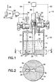
- FIGURE 1 is a schematic representation of a chemical vapor deposition system 10 including a reagent supply vessel assembly shown in elevation view and partial cross-section, according to an illustrative embodiment of the invention.
- the reagent supply vessel 12 includes side wall member 14, which may for example comprise a cylindrical wall or wall segments corporately defining an enclosing side wall structure, e.g., of square or other non-circular cross-section, top wall member 16 and floor member 18.
- the side wall, top wall and floor members define an enclosed interior volume 20 of the vessel, which in operation may contain a gas space 22 overlying a liquid 24 defining a liquid surface 26 at the gas-liquid interface.
- the floor member 18, which as shown in FIGURE 1 has a main floor surface 34, is provided with a sump cavity 28 therein.
- the sump cavity 28 extends downwardly from the main floor surface 34 into the floor member 18, and is bounded by the sub-floor surface 32 and the bounding side wall surface 30 of the cavity.
- the reagent supply vessel 12 is equipped with pressurized gas introduction means, which in the embodiment shown comprises a pressurized gas feed tube 36 having a gas flow control valve 38 coupled therewith to control the flow of pressurized gas into the interior volume of the reagent supply vessel.
- the gas feed tube 36 may as illustrated pass through a suitable opening in the top wall member 16 of the vessel, and terminate at an open lower end 40 in the gas space 22 of the interior volume.
- the gas feed tube 36 is joined by coupling 37 to a supply line 52 from the gas supply unit 50, so that the pressurized gas from the supply unit 50 flows through supply line 52 to gas feed tube 36 and is discharged in the gas space 22 of the vessel at the open lower end 40 of the gas feed tube, to exert pressure on the surface 26 of the liquid 24 for dispensing of the liquid as hereafter more fully described.
- the gas supply unit 50 may be of any suitable type, as for example a high pressure gas cylinder, a cryogenic air separation plant, or a pressure swing air separation unit, furnishing pressurizing gas, e.g., nitrogen, argon, oxygen, etc., to the supply line 52.
- the vessel 12 also is equipped with a dip tube 42 extending from a lower open end 46 in the interior volume of the vessel, to an upper end exteriorly of the vessel, which is joined to a liquid feed line 54.
- the dip tube thus passes through the top wall member 16 of the vessel, and is coupled to a flow control valve 44 as shown, for selectively adjusting the flow rate of the dispensed liquid which is flowed through the dip tube to line 54.
- the dip tube lower open end 46 is positioned in close proximity to the sub-floor surface 32. The spacing between the lower open end 46 of the dip tube and the sub-floor surface is selected so that the lower open end 46 is as close as possible to the sub-floor surface without interfering with the flow of liquid 24 into the interior passage of the dip tube.
- the lower end of the dip tube may be in sufficiently close proximity to the sub-floor surface of the sump cavity to permit high levels, e.g., at least 90% of the liquid contained in the vessel to be dispensed without gas bypassing.
- the exact clearance between the lower open end 46 of the dip tube and the sub-floor surface 32 will depend on various factors including the viscosity of the liquid being dispensed, the discharge flow rates of the liquid desired in operation of the chemical vapor deposition system, the inner diameter of the dip tube, the roughness of the interior surface of the dip tube, etc., but may be determined without undue experimentation by the simple expedient of varying the clearance dimension in successive test runs with a vertically adjustable dip tube of a design test vessel, and determining the output flows, pressure drop, etc. associated therewith, to select an appropriate clearance dimension for a specific end use application of the invention.
- Liquid feed line 54 thus receives the liquid reagent which is discharged by the dip tube 42 from the reagent supply vessel 12, and flows same to the vaporizer 56 for the chemical vapor deposition system.
- the liquid reagent deriving from supply vessel 12 is vaporized to form a source vapor for the subsequent vapor deposition operation.
- the vaporizer 56 may also receive a carrier gas for combining with or shrouding the source vapor produced by vaporization of the liquid reagent.
- the source vapor may be passed to the downstream vapor deposition operation in neat form.
- the source vapor from the vaporizer 56 is flowed in vapor feed line 58 to the chemical vapor deposition chamber 60.
- a wafer 64 or other substrate element is mounted on a heatable susceptor 62 or other mount structure, in receiving relationship to the source vapor introduced to the chamber from vapor feed line 58.
- the vapor is contacted with the wafer 64, to deposit thereon the desired component(s) of the source vapor, and form a resulting material layer or deposit on the wafer.
- the effluent gas from the chemical vapor deposition is discharged from chamber 60 in effluent discharge line 66, and may be passed to recycle, recovery, waste treatment, disposal, or other disposition means (not shown in FIGURE 1).
- the vessel is equipped with a liquid level sensor 48 which extends from upper portion 70, downwardly through the collar 72 in the top wall member 16 of the vessel, to a lower end 74 in close proximity to the sub-floor surface 32 of the sump cavity 28 of the vessel.
- the upper portion 70 of the liquid level sensor 48 is connected by liquid level sensing signal transmission line 88 to a central processing unit 90, for transmission of sensed liquid level signals from the sensor 48 to the central processing unit during operation of the system.
- the central processing unit 90 which may comprise suitable microprocessor, computer, or other appropriate control means, is also joined by control signal transmission line 92 to the valve 38 (e.g., via a suitable valve actuator element, not shown in the schematic illustration of FIGURE 1) to selectively adjust the valve 38 and control the flow of pressurized gas to the reagent supply vessel.
- the central processor unit 90 is also joined by control signal transmission line 94 to the liquid dispensing control valve 44 (e.g., via a suitable valve actuator element, not shown in the schematic illustration of FIGURE 1), to control the flow of reagent liquid from the vessel 12 to the vaporizer 56.
- the sump cavity 28 has a depth t, measured as the vertical distance from the plane of the main floor surface 34 to the sub-floor surface 32, which is significant in relation to the thickness T of the floor member 18.
- FIGURE 2 is a cross-sectional plan view of the liquid reagent supply vessel 12 of FIGURE 1, taken along line 2-2 of FIGURE 1.
- the sump cavity 28 is of a generally dog-bone or dumbbell shape in top plan view, comprising the dip tube well 80, the liquid level sensor well 82, and the yoke passage 84 communicating wells 80 and 82 with one another.
- the sump cavity 28 when viewed in such plan view is seen to occupy a minor portion of the cross-sectional floor area of the vessel.
- such plan view cross-sectional area of the sump cavity is preferably less than about 25 % of the total cross-sectional area of the vessel floor, and more preferably less than about 15 % of the total cross-sectional area of the vessel floor.
- the cross-sectional area of the sump cavity may be in the range of from about 5 to about 20% of the total cross-sectional area of the vessel (floor area).
- the side-walls of the sump cavity may be sloped, straight or of any other geometry or orientation.
- the sump cavity may comprise separate discrete wells for the respective dip tube and liquid level sensor lower end portions. These wells may be communicated with one another by a passage extending through the floor member of the supply vessel and communicating at respective ends with the wells in the vicinity of the sub-floor surfaces of the wells.
- Such interconnecting passage may for example be a generally horizontally extending passage, or it may for example comprise a U-shape or manometric-type passage between the respective wells of the floor member of the vessel, or it may have any other suitable shape and configuration for the purpose of communicating the wells or constituent parts of the sump cavity.
- the respective wells may be discrete and non-interconnected in character, being provided as separate bores or channels in the floor member of the vessel.
- the sump cavity may be formed in the floor member of the liquid reagent supply vessel by any suitable manufacturing method, including casting, molding, etching, machining (drilling, milling, electric arc machining, etc.), or any other method providing a cavity structure in the floor member which provides a liquid holding volume of reduced cross-sectional area in the lower portion of the interior volume of the liquid reagent supply vessel, so that a given volume of liquid occupies a greater height than would be the case in an interior volume of uniform cross-sectional area over its entire vertical extent.
- any suitable manufacturing method including casting, molding, etching, machining (drilling, milling, electric arc machining, etc.), or any other method providing a cavity structure in the floor member which provides a liquid holding volume of reduced cross-sectional area in the lower portion of the interior volume of the liquid reagent supply vessel, so that a given volume of liquid occupies a greater height than would be the case in an interior volume of uniform cross-sectional area over its entire vertical extent.
- FIGURES 1 and 2 utilizing a liquid level sensor of the type including a sensor element extending downwardly in the vessel to a lower end disposed in the lower portion of the vessel's interior volume according claim 1, is generally preferred for reasons of simplicity, reliability and low cost.
- liquid reagent is placed in the supply vessel 12, and pressurized gas is flowed from gas supply unit 50 through gas supply line 52 to the gas feed tube 36 from which it is discharged at open end 40 of the gas feed tube into the gas space 22 in the interior volume 20 of the vessel 12.
- the pressurized gas forces the liquid 24 into the lower end 46 of the dip tube 42, from which it flows into line 54 and is passed to the vaporizer 56 for vaporization therein.
- the resulting reagent vapor is flowed in line 58 to the chemical vapor deposition chamber 60 for deposition of the desired material layer or deposit on the substrate 64, and discharge of effluent vapor from the chamber 60 in effluent discharge line 66.
- the liquid level of the liquid 24 in vessel 12 is detected by liquid level sensor 48.
- the liquid level defined by liquid surface 26 progressively declines and eventually lowers into the sump cavity 28 to a minimum liquid head (height of liquid in the sump cavity), at which point the central processing unit 90 receives a corresponding sensed liquid level signal by liquid level sensing signal transmission line 88.
- the central processing unit 90 responsively transmits a control signal in control signal transmission line 92 to the valve 38 to close the valve and shut off the flow of pressurized gas to the reagent supply vessel, and also concurrently transmits a control signal in control signal transmission line 94 to close the liquid dispensing control valve 44, to shut off the flow of reagent liquid from the vessel 12 to the vaporizer.
- the liquid sensor By acting at the end of the liquid dispensing operation on a reduced cross-section, increased height liquid volume in the sump cavity in accordance with the present invention, relative to the larger cross-section, lower height liquid volume which is characteristic of the reagent supply vessels of the prior art, the liquid sensor is able to monitor the liquid reagent to a closer approach to complete liquid utilization than has heretofore been possible.
- the placement of the lower inlet end of the dip tube liquid discharge conduit in the sump cavity of the vessel permits the liquid flow to be continued to a closer approach to complete exhaustion of the liquid contents of the vessel, without risk of slugging or bypassing of pressurizing gas into the liquid discharge conduit, than has been feasible in the practice of the prior art.
- the means and method of the present invention thus achieves a substantial advance in the art, in the provision of a system for supply and dispensing of a liquid reagent, which permits 95-98% of the volume of the originally furnished liquid reagent to be utilized in the application for which the liquid reagent is selectively dispensed.
- the means and method of the present invention to reduce the wastage of the liquid reagent to levels as low as 2-5% of the volume originally loaded into the dispensing vessel.
- the practice of the present invention markedly improves the economics of the liquid supply and dispensing system, and the process in which the dispensed liquid is employed.
- the invention in some instances may permit the cost-effective utilization of liquid reagents which were as a practical matter precluded by the wastage levels characteristic of prior art practice.
- the reduced liquid inventory in the supply vessel at the end of the dispensing operation permits the switch-over time, during which the exhausted supply vessel is changed out from the process system, and replaced with another vessel for further processing, to be minimized as a result of the greater on-stream time for the supply vessel owing to increased usage of the originally charged liquid therefrom, relative to such prior practice.
- the closed vessel dispensing assembly of the invention may usefully be employed for supplying reagents to liquid delivery chemical vapor deposition systems for the deposition of thin film materials in the manufacture of semiconductor materials and devices.
- the dispensing assembly achieves a high extent of withdrawal of the reagent liquid from the vessel, to maximize the use of the supplied reagent and minimize the residuum of liquid in the vessel at the conclusion of the dispensing operation.
Landscapes
- Chemical & Material Sciences (AREA)
- Engineering & Computer Science (AREA)
- Mechanical Engineering (AREA)
- Chemical Kinetics & Catalysis (AREA)
- Organic Chemistry (AREA)
- General Chemical & Material Sciences (AREA)
- Materials Engineering (AREA)
- Metallurgy (AREA)
- Chemical Vapour Deposition (AREA)
- Feeding, Discharge, Calcimining, Fusing, And Gas-Generation Devices (AREA)
- Containers And Packaging Bodies Having A Special Means To Remove Contents (AREA)
Abstract
Description
- The present invention relates generally to a closed vessel liquid reagent dispensing assembly of the type in which liquid is dispensed from a dip-tube liquid discharge conduit from a gas-pressurized vessel, and in which the liquid level may be sensed by a sensor extending downwardly in the vessel and terminating just short of the floor thereof.
- In the field of chemical vapor deposition using liquid delivery systems for the supply of a liquid reagent to a vaporizer, wherein the liquid is vaporized by the vaporizer and passed to a chemical vapor deposition reactor for forming the desired material layer on a substrate from the reagent vapor, the liquid reagents employed are often costly.
- This is particularly true in instances where the material sought to be deposited in the chemical vapor deposition operation is a precious metal or rare element, or where the liquid reagent is difficult and/or expensive itself to synthesize. Examples include many liquid reagents for liquid delivery chemical vapor deposition manufacturing of semiconductor and superconductor devices and precursor structures thereof, e.g., liquid source compounds, and solutions of solubilizable or suspendable source compounds, for platinum, gold, titanium, lead, palladium, zirconium, bismuth, strontium, barium, calcium, antimony, thallium, tantalum, etc.
- Owing to the costly character of such liquid reagents, it is obviously desirable to maximize the utilization of the reagent in a given application, and to minimize wastage or loss of the valuable liquid reagent material.
- The conventional supply vessel assembly used in liquid delivery chemical vapor deposition operations typically comprises a closed vessel including floor and wall members defining an interior volume, bounded by interior floor and wall surfaces, for holding liquid reagent.
- The vessel is coupled with pressurized gas supply means for introducing pressurized gas into the interior volume of the vessel, to thereby pressurizingly dispense liquid reagent from the vessel. For such purpose, the vessel may be provided with a "pressurization post,'' or inlet tube, which is joined by a conduit to a source of pressurized gas, such as a high pressure gas cylinder containing a displacement gas such as nitrogen, argon, or other suitable gas species, which serves to impose pressure on the volume of liquid reagent in the vessel, to cause the egress of liquid from the vessel under dispensing conditions.
- Liquid is discharged from such vessel by a "dip tube," or liquid discharge tube, which is arranged to extend upwardly and exteriorly of the vessel, from a lower open end in close proximity to the flat or generally planar floor surface of the vessel's interior volume. The aforementioned pressurization of the liquid reagent under dispensing conditions thereby causes the liquid reagent to flow into the open lower end of the dip tube and upwardly therethrough for discharge exteriorly of the vessel, e.g., into a line feeding the vaporizer for the chemical vapor deposition unit, whereby reagent source vapor is formed and subsequently introduced to the chemical vapor deposition reactor for the deposition of a material layer on the substrate therein.
- The conventional liquid reagent vessel of the above-described character also is equipped with a liquid level sensor, of a type extending downwardly in the interior volume and terminating at a lower end in close proximity to the floor surface in the interior volume of the vessel. The sensor is designed to detect the level of the liquid as it is being depleted.
- The liquid level sensor and the dip tube need a certain height of liquid to function properly. If the liquid level is too low, then the level sensor can cease to function and more importantly, gas can be pressurized up the dip tube. The passage of gas up the dip tube is undesirable in liquid delivery applications, since the "bypassing" gas replaces the liquid sought to be vaporized in the egressing fluid. As a result, the vaporizer may overheat or develop hot spots, and the downstream process may be starved of the desired flux or flow rate of source vapor, which in turn can cause the deposited material to be stoichiometrically or otherwise compositionally deficient or even useless for its intended purpose.
- To overcome this problem, it has been conventional practice to utilize only 80-90% of the liquid reagent volume originally provided in the vessel, meaning that 10 to 20% of the original volume of reagent liquid is not used (and therefore wasted), to ensure that the liquid level is high enough for liquid level sensing at all times. Because the semiconductor manufacturing process operates in a batch process fashion, with respect to the deposition of constituent materials on the wafer substrate from the vaporized source material, the non-used reagent from the supply vessel becomes part of the overall waste from the semiconductor manufacturing plant.
- In instances where the liquid reagent is costly and valuable, such wastage of the liquid reagent severely adversely impacts the process economics, as well as representing a significant burden in terms of disposition of the waste liquid and its environmental impact.
-
US-A-4,676,404 discloses an apparatus for feeding drug liquid from a can comprising a regular level gauge. -
US-A-5,383,574 discloses a system and method for dispensing liquid from storage container wherein liquid level sensors are a part of a complex system. -
US-A-5,582,647 describes a material supplying apparatus having an exact liquid level sensor wherein the floor of the contained used to contain the liquid is somewhat peaked but does not have a cavity where the liquid level sensor could end. - Accordingly, it would be a significant advance in the art, and is accordingly an object of the present invention, to provide an improved liquid reagent supply means and method which increases the usage of the liquid reagent, and correspondingly reduces waste thereof, relative to liquid reagent supply means and method of the prior art.
- Other objects and advantages of the present invention will be more fully apparent from the ensuing disclosure and appended claims.
- The present invention relates to an apparatus for dispensing a liquid reagent, in which the liquid reagent is dispensed from a dip-tube liquid discharge conduit from a gas-pressurized vessel, and in which the floor of the gas-pressurized vessel provides a sump cavity in which the lower end of the dip-tube liquid discharge conduit is disposed.
- Such arrangement achieves higher utilization of the liquid than the flat-floored vessel constructions of the prior art.
- In a specific aspect, the invention relates to a liquid reagent dispensing assembly, comprising:
- a gas-pressurizable vessel including a floor, and an interior volume bounded by interior wall and floor surfaces,
- a dip-tube liquid discharge conduit for discharging liquid from the gas-pressurized vessel, wherein the dip tube extends downwardly in the interior volume of the vessel to a lower end of the dip tube disposed in a lower portion of the interior volume,
- a liquid level sensor for sensing liquid reagent level in the vessel interior volume,
- the floor of the vessel having a cavity therein extending downwardly from the surface of the floor, and
- the lower end of the dip tube being positioned in the cavity.
- In such assembly, the liquid level sensor includes a sensor element extending downwardly and terminating at a lower end positioned in the sump cavity structure.
- In one embodiment, the sump cavity is configured as a dual well structure in the floor member of the vessel, with one well containing the lower extremity of the dip tube, and the other well containing the lower end of the liquid sensor element.
- The liquid reagent dispensing assembly may in another embodiment include a liquid reagent flow circuit joining the dip-tube liquid discharge conduit in reagent liquid flow communication with a liquid delivery chemical vapor deposition system including a vaporizer and chemical vapor deposition chamber.
- The sump cavity may suitably occupy a minor fraction, e.g., 25% or less, of the cross-section floor surface area of the vessel, and be readily constructed by machining, milling, boring or routing of the floor member of the vessel.
- The reagent supply vessel assembly of the invention may be employed in a wide variety of process systems, including for example chemical vapor deposition systems wherein the liquid reagent from the supply vessel is passed to a vaporizer and vaporized to form a source vapor which is flowed to a chemical vapor deposition chamber for deposition of a material layer on a substrate therein from the source vapor.
- Other aspects, features and embodiments of the invention will be more fully apparent from the ensuing disclosure and appended claims.
-
- FIGURE 1 is a schematic representation of a chemical vapor deposition system including a reagent supply vessel shown in elevation view and partial cross-section, according to an illustrative embodiment of the invention.
- FIGURE 2 is a cross-sectional plan view of the reagent source vessel of FIGURE 1, taken along line 2-2 of FIGURE 1.
- Referring to the drawings, FIGURE 1 is a schematic representation of a chemical
vapor deposition system 10 including a reagent supply vessel assembly shown in elevation view and partial cross-section, according to an illustrative embodiment of the invention. - In this system, the
reagent supply vessel 12 includesside wall member 14, which may for example comprise a cylindrical wall or wall segments corporately defining an enclosing side wall structure, e.g., of square or other non-circular cross-section,top wall member 16 andfloor member 18. The side wall, top wall and floor members define an enclosedinterior volume 20 of the vessel, which in operation may contain agas space 22 overlying aliquid 24 defining aliquid surface 26 at the gas-liquid interface. - In accordance with the invention, the
floor member 18, which as shown in FIGURE 1 has amain floor surface 34, is provided with asump cavity 28 therein. Thesump cavity 28 extends downwardly from themain floor surface 34 into thefloor member 18, and is bounded by thesub-floor surface 32 and the boundingside wall surface 30 of the cavity. - The
reagent supply vessel 12 is equipped with pressurized gas introduction means, which in the embodiment shown comprises a pressurizedgas feed tube 36 having a gasflow control valve 38 coupled therewith to control the flow of pressurized gas into the interior volume of the reagent supply vessel. Thegas feed tube 36 may as illustrated pass through a suitable opening in thetop wall member 16 of the vessel, and terminate at an openlower end 40 in thegas space 22 of the interior volume. - The
gas feed tube 36 is joined bycoupling 37 to asupply line 52 from thegas supply unit 50, so that the pressurized gas from thesupply unit 50 flows throughsupply line 52 togas feed tube 36 and is discharged in thegas space 22 of the vessel at the openlower end 40 of the gas feed tube, to exert pressure on thesurface 26 of theliquid 24 for dispensing of the liquid as hereafter more fully described. Thegas supply unit 50 may be of any suitable type, as for example a high pressure gas cylinder, a cryogenic air separation plant, or a pressure swing air separation unit, furnishing pressurizing gas, e.g., nitrogen, argon, oxygen, etc., to thesupply line 52. - The
vessel 12 also is equipped with adip tube 42 extending from a loweropen end 46 in the interior volume of the vessel, to an upper end exteriorly of the vessel, which is joined to aliquid feed line 54. The dip tube thus passes through thetop wall member 16 of the vessel, and is coupled to aflow control valve 44 as shown, for selectively adjusting the flow rate of the dispensed liquid which is flowed through the dip tube toline 54. The dip tube loweropen end 46 is positioned in close proximity to thesub-floor surface 32. The spacing between the loweropen end 46 of the dip tube and the sub-floor surface is selected so that the loweropen end 46 is as close as possible to the sub-floor surface without interfering with the flow ofliquid 24 into the interior passage of the dip tube. For example, the lower end of the dip tube may be in sufficiently close proximity to the sub-floor surface of the sump cavity to permit high levels, e.g., at least 90% of the liquid contained in the vessel to be dispensed without gas bypassing. - The exact clearance between the lower
open end 46 of the dip tube and thesub-floor surface 32 will depend on various factors including the viscosity of the liquid being dispensed, the discharge flow rates of the liquid desired in operation of the chemical vapor deposition system, the inner diameter of the dip tube, the roughness of the interior surface of the dip tube, etc., but may be determined without undue experimentation by the simple expedient of varying the clearance dimension in successive test runs with a vertically adjustable dip tube of a design test vessel, and determining the output flows, pressure drop, etc. associated therewith, to select an appropriate clearance dimension for a specific end use application of the invention. -
Liquid feed line 54 thus receives the liquid reagent which is discharged by thedip tube 42 from thereagent supply vessel 12, and flows same to thevaporizer 56 for the chemical vapor deposition system. In thevaporizer 56, the liquid reagent deriving fromsupply vessel 12 is vaporized to form a source vapor for the subsequent vapor deposition operation. Thevaporizer 56 may also receive a carrier gas for combining with or shrouding the source vapor produced by vaporization of the liquid reagent. Alternatively, the source vapor may be passed to the downstream vapor deposition operation in neat form. - In any event, the source vapor from the
vaporizer 56 is flowed invapor feed line 58 to the chemicalvapor deposition chamber 60. In the chemicalvapor deposition chamber 60, awafer 64 or other substrate element is mounted on aheatable susceptor 62 or other mount structure, in receiving relationship to the source vapor introduced to the chamber fromvapor feed line 58. The vapor is contacted with thewafer 64, to deposit thereon the desired component(s) of the source vapor, and form a resulting material layer or deposit on the wafer. The effluent gas from the chemical vapor deposition is discharged fromchamber 60 ineffluent discharge line 66, and may be passed to recycle, recovery, waste treatment, disposal, or other disposition means (not shown in FIGURE 1). - Referring again to the
reagent supply vessel 12, the vessel is equipped with aliquid level sensor 48 which extends fromupper portion 70, downwardly through thecollar 72 in thetop wall member 16 of the vessel, to alower end 74 in close proximity to thesub-floor surface 32 of thesump cavity 28 of the vessel. Theupper portion 70 of theliquid level sensor 48 is connected by liquid level sensingsignal transmission line 88 to acentral processing unit 90, for transmission of sensed liquid level signals from thesensor 48 to the central processing unit during operation of the system. - The
central processing unit 90, which may comprise suitable microprocessor, computer, or other appropriate control means, is also joined by controlsignal transmission line 92 to the valve 38 (e.g., via a suitable valve actuator element, not shown in the schematic illustration of FIGURE 1) to selectively adjust thevalve 38 and control the flow of pressurized gas to the reagent supply vessel. - The
central processor unit 90 is also joined by controlsignal transmission line 94 to the liquid dispensing control valve 44 (e.g., via a suitable valve actuator element, not shown in the schematic illustration of FIGURE 1), to control the flow of reagent liquid from thevessel 12 to thevaporizer 56. - As shown in FIGURE 1, the
sump cavity 28 has a depth t, measured as the vertical distance from the plane of themain floor surface 34 to thesub-floor surface 32, which is significant in relation to the thickness T of thefloor member 18. By this arrangement, the lower ends 46 and 74 of thedip tube 42 and theliquid level sensor 48, respectively, as arranged in close proximity to the sump cavity sub-floor, to operate in the sub-volume of liquid in the sump cavity, and thereby increase the extent of utilization of the liquid 24 provided in the vessel. - FIGURE 2 is a cross-sectional plan view of the liquid
reagent supply vessel 12 of FIGURE 1, taken along line 2-2 of FIGURE 1. In this illustrative embodiment, thesump cavity 28 is of a generally dog-bone or dumbbell shape in top plan view, comprising thedip tube well 80, the liquid level sensor well 82, and theyoke passage 84 communicatingwells - The
sump cavity 28 when viewed in such plan view is seen to occupy a minor portion of the cross-sectional floor area of the vessel. In general, such plan view cross-sectional area of the sump cavity is preferably less than about 25 % of the total cross-sectional area of the vessel floor, and more preferably less than about 15 % of the total cross-sectional area of the vessel floor. For example, the cross-sectional area of the sump cavity may be in the range of from about 5 to about 20% of the total cross-sectional area of the vessel (floor area). The side-walls of the sump cavity may be sloped, straight or of any other geometry or orientation. - It will be appreciated that the conformation, including the shape, geometry and dimensions, of the sump cavity in the practice of the present invention may be widely varied in practice.
- For example, the sump cavity may comprise separate discrete wells for the respective dip tube and liquid level sensor lower end portions. These wells may be communicated with one another by a passage extending through the floor member of the supply vessel and communicating at respective ends with the wells in the vicinity of the sub-floor surfaces of the wells. Such interconnecting passage may for example be a generally horizontally extending passage, or it may for example comprise a U-shape or manometric-type passage between the respective wells of the floor member of the vessel, or it may have any other suitable shape and configuration for the purpose of communicating the wells or constituent parts of the sump cavity. Alternatively, the respective wells may be discrete and non-interconnected in character, being provided as separate bores or channels in the floor member of the vessel.
- The sump cavity may be formed in the floor member of the liquid reagent supply vessel by any suitable manufacturing method, including casting, molding, etching, machining (drilling, milling, electric arc machining, etc.), or any other method providing a cavity structure in the floor member which provides a liquid holding volume of reduced cross-sectional area in the lower portion of the interior volume of the liquid reagent supply vessel, so that a given volume of liquid occupies a greater height than would be the case in an interior volume of uniform cross-sectional area over its entire vertical extent.
- The arrangement shown in FIGURES 1 and 2 utilizing a liquid level sensor of the type including a sensor element extending downwardly in the vessel to a lower end disposed in the lower portion of the vessel's interior volume according claim 1, is generally preferred for reasons of simplicity, reliability and low cost.
- In operation of the system illustrated with reference to FIGURES 1 and 2, liquid reagent is placed in the
supply vessel 12, and pressurized gas is flowed fromgas supply unit 50 throughgas supply line 52 to thegas feed tube 36 from which it is discharged atopen end 40 of the gas feed tube into thegas space 22 in theinterior volume 20 of thevessel 12. The pressurized gas forces the liquid 24 into thelower end 46 of thedip tube 42, from which it flows intoline 54 and is passed to thevaporizer 56 for vaporization therein. - After vaporization of the liquid reagent in
vaporizer 56, the resulting reagent vapor is flowed inline 58 to the chemicalvapor deposition chamber 60 for deposition of the desired material layer or deposit on thesubstrate 64, and discharge of effluent vapor from thechamber 60 ineffluent discharge line 66. - During this operation, the liquid level of the liquid 24 in
vessel 12 is detected byliquid level sensor 48. The liquid level defined byliquid surface 26 progressively declines and eventually lowers into thesump cavity 28 to a minimum liquid head (height of liquid in the sump cavity), at which point thecentral processing unit 90 receives a corresponding sensed liquid level signal by liquid level sensingsignal transmission line 88. Thecentral processing unit 90 responsively transmits a control signal in controlsignal transmission line 92 to thevalve 38 to close the valve and shut off the flow of pressurized gas to the reagent supply vessel, and also concurrently transmits a control signal in controlsignal transmission line 94 to close the liquiddispensing control valve 44, to shut off the flow of reagent liquid from thevessel 12 to the vaporizer. - By acting at the end of the liquid dispensing operation on a reduced cross-section, increased height liquid volume in the sump cavity in accordance with the present invention, relative to the larger cross-section, lower height liquid volume which is characteristic of the reagent supply vessels of the prior art, the liquid sensor is able to monitor the liquid reagent to a closer approach to complete liquid utilization than has heretofore been possible.
- At the same time, the placement of the lower inlet end of the dip tube liquid discharge conduit in the sump cavity of the vessel permits the liquid flow to be continued to a closer approach to complete exhaustion of the liquid contents of the vessel, without risk of slugging or bypassing of pressurizing gas into the liquid discharge conduit, than has been feasible in the practice of the prior art.
- The means and method of the present invention thus achieves a substantial advance in the art, in the provision of a system for supply and dispensing of a liquid reagent, which permits 95-98% of the volume of the originally furnished liquid reagent to be utilized in the application for which the liquid reagent is selectively dispensed.
- Correspondingly, in operations such as the manufacture of semiconductor and superconductor products, it is possible with the means and method of the present invention to reduce the wastage of the liquid reagent to levels as low as 2-5% of the volume originally loaded into the dispensing vessel.
- Accordingly, the practice of the present invention markedly improves the economics of the liquid supply and dispensing system, and the process in which the dispensed liquid is employed. The invention in some instances may permit the cost-effective utilization of liquid reagents which were as a practical matter precluded by the wastage levels characteristic of prior art practice.
- As a further benefit of the present invention, the reduced liquid inventory in the supply vessel at the end of the dispensing operation, relative to prior practice, permits the switch-over time, during which the exhausted supply vessel is changed out from the process system, and replaced with another vessel for further processing, to be minimized as a result of the greater on-stream time for the supply vessel owing to increased usage of the originally charged liquid therefrom, relative to such prior practice.
- The closed vessel dispensing assembly of the invention may usefully be employed for supplying reagents to liquid delivery chemical vapor deposition systems for the deposition of thin film materials in the manufacture of semiconductor materials and devices.
- In such applications, the dispensing assembly achieves a high extent of withdrawal of the reagent liquid from the vessel, to maximize the use of the supplied reagent and minimize the residuum of liquid in the vessel at the conclusion of the dispensing operation.
Claims (21)
- A liquid reagent dispensing assembly, comprising:a gas-pressurizable vessel (12) including a floor, and an interior volume (20) bounded by interior wall and floor surfaces,a dip-tube liquid discharge conduit (42) for discharging liquid (24) from the gas-pressurizable vessel, wherein the dip tube extends downwardly in the interior volume of the vessel to a lower end of the dip tube disposed in a lower portion of the interior volume,a liquid level sensor (48) for sensing liquid reagent level in the vessel interior volume,characterized in thatthe floor of the vessel has a sump cavity (28) therein extending downwardly from the surface of the floor,the lower end of the dip-tube (46) is positioned in said sump cavity, andthe liquid level sensor (48) comprises a sensor element extending downwardly and terminating at a lower end that is positioned in said sump cavity.
- The liquid reagent dispensing assembly according to claim 1, further comprising a liquid reagent flow circuit joining the dip-tube liquid discharge conduit (42) in reagent liquid flow communication with a liquid delivery chemical vapour deposition system.
- The liquid reagent dispensing assembly according to claim 2, wherein the liquid reagent flow circuit contains a flow control valve (44) to regulate flow rate of discharged liquid reagent through the circuit.
- The liquid reagent dispensing assembly according to any of claims 1-3, wherein the sump cavity (28) occupies a minor fraction of the area of the floor surface (34).
- The liquid reagent dispensing assembly according to claim 4, wherein the sump cavity (28) occupies less than 25 % of the floor surface area (34).
- The liquid reagent dispensing assembly according to any of claims 1-5, wherein the sump cavity (28) has a dumbbell shape in top plan view of the floor surface (34).
- The liquid reagent dispensing assembly according to any of claims 1-6, wherein the sump cavity (28) comprises two transversely space-apart wells (80, 82) in liquid flow communication with one another, with one of the wells having the lower open end of the dip tube (42) disposed therein and the other of the wells having the lower end of the liquid level sensor element disposed therein.
- The liquid reagent dispensing assembly according to any of claims 1-7, wherein
the vessel (12) includes floor and wall members (16,18) defining an interior volume (20), bounded by interior floor and wall surfaces, for holding liquid reagent (24), and into which pressurized gas is introduceable to dispense the liquid reagent from the vessel (12);
the floor members (18) of the vessel (12) have a sump cavity (28) therein extending downwardly from a main floor surface (34) of the floor member (18) to a sub-floor surface (32) of the sump cavity (28); and/or
the lower open end (46) of the dip-tube is positioned in the sump cavity (28) in close proximity to the sub-floor surface (32) of the sump cavity. - The liquid reagent dispensing assembly according to claim 8 wherein the dip-tube (42) extends through a top portion of the closed vessel (12) and generally vertically downwardly into the sump cavity (28).
- The liquid reagent dispensing assembly according to claim 9, wherein the close proximity to the sub-floor surface (32) permits utilization of at least 90 % of liquid reagent when liquid reagent is contained in the closed vessel (12).
- The liquid reagent dispensing assembly according to any of claims 1-10, wherein the assembly further comprises a pressurized gas feed tube (36) that is operationally connected to a gas flow control valve (38) and further comprising:a liquid level signal transmission line (88) operationally connecting the liquid level sensor (48) to a central processing unit (90); anda gas control signal transmission line operationally connecting the central processing unit (90) to the gas flow control valve (38);such that when the level of liquid reagent in the closed vessel reaches a minimum reagent head the liquid level sensor (48) is capable of transmitting a signal in the liquid reagent level signal transmission line (88) to the central processing unit (90) and the central processing unit (90) is capable of receiving the level signal from the liquid reagent level signal transmission line (88) and transmitting a corresponding gas control signal in the gas control signal transmission line to the gas flow control valve (38) to close the gas flow control valve (38).
- The liquid reagent dispensing assembly according to any of claims 1-10, wherein the dip-tube (42) is operationally connected to a reagent liquid flow control valve (44) and further comprising:a liquid level signal transmission line (88) operationally connecting the liquid level sensor (48) to a central processing unit (90); anda reagent control signal transmission line (92) operationally connecting the central processing unit (90) to the reagent liquid flow control valve (44);such that when the level of liquid reagent in the closed vessel reaches a minimum reagent head the liquid level sensor (48) is capable of transmitting a reagent liquid level signal in the liquid reagent level signal transmission line (88) to the central processing unit (90) and the central processing unit (90) is capable of receiving the level signal from the liquid reagent level signal transmission line (88) and transmitting a corresponding reagent liquid control signal in the control signal transmission line (94) to the reagent liquid flow control valve (44) to close the reagent flow control valve (44).
- The liquid reagent dispensing assembly according to any of claims 1-12, further comprising a liquid reagent (24) contained in the interior volume (20) of the closed vessel (12).
- The liquid reagent dispensing assembly according to claim 13, wherein the liquid reagent (24) comprises a precursor for a metal selected from the group consisting of: platinum, gold, titanium, lead, palladium, zirconium, bismuth, strontium, barium, calcium, antimony, thallium and tantalum.
- The liquid reagent dispensing assembly according to any of claims 1-14, wherein the sump cavity (28) comprises a liquid level sensor well (82) in flow communication with a dip tube well (80).
- The liquid reagent dispensing assembly according to Claim 15, wherein the liquid level sensor well (82) is connected to the dip tube well (80) by a yoke passage (84), thereby defining a dumbbell conformation of the sump cavity (28).
- The liquid reagent dispensing assembly according to any of claims 1-16, wherein the sump cavity (28) is defined at least in part by a sloping wall surface.
- The liquid reagent dispensing assembly according to any of claims 1-17, further comprising a pressurized gas source coupled to the pressurized gas feed tube (36).
- The liquid reagent dispensing assembly according to claim 18, wherein the pressurized gas source is selected from the group consisting of: a high pressure gas cylinder, a cryogenic air separation plant and a pressure swing air separation unit.
- An apparatus comprising:a cylindrically shaped closed vessel (12) bounded on its upper end by a top wall member (16) and on its lower end by a bottom wall member to define therewithin an interior volume (20) for holding liquid reagent (24), the bottom wall member having a main floor surface and containing a dumbbell-shaped sump cavity (28);the sump cavity (28) being bounded at its lower end by a subfloor surface (32) and comprising a liquid level sensor well (82) connected to a dip tube well (82) by a yoke passage (84), thereby defining a dumbbell conformation of the sump cavity (28);a liquid level sensor (48) extending from an upper end exterior of the vessel (12) through a centrally located portion of the top wall member (16) downwardly into the interior volume of the closed vessel to a lower end in the sump cavity (28);a dip-tube reagent liquid discharge conduit (42) extending from an upper end exterior of the vessel downwardly through the top wall member into the interior volume (20) of the closed vessel (12) to a lower end in the sump cavity (28), with the lower end (46) of the dip-tube (42) being located in non-interfering proximity to the sub-floor surface (32) of the sump cavity (28), and with the upper end of the dip-tube (42) being coupled to a flow control valve (44);a pressurized gas feed tube (36) operationally connected at one end thereof to a pressurized gas source (50) and at another end thereof to the closed vessel (12) for delivery of pressurized gas from the pressurized gas source (50) into the interior volume (20) of the vessel (12), the pressurized gas feed tube (36) containing a pressurized gas flow control valve(38) therein for control of flow of the pressurized gas therethrough;a liquid level signal transmission line (88) operationally connecting the liquid level sensor (48) to a central processing unit (90);a gas control signal transmission line (92) operationally connecting the central processing unit (90) to the gas flow control valve (38); anda reagent liquid control signal transmission line (94) operationally connecting the central processing unit (90) to the reagent liquid flow control valve (44);such that when pressurized gas is supplied through the pressurized gas feed tube (36) to the interior volume (20) of the closed vessel (12), reagent contained therein is forced into the dip-tube (42) and out of the interior volume (20), and when the level of liquid reagent in the closed vessel (12) reaches a minimum reagent head the liquid level sensor (48) is capable of transmitting a level signal in the liquid level signal transmission line (88) to the central processing unit (90) and the central processing unit (90) is capable of receiving the level signal from the liquid level signal transmission line (88) and transmitting (i) a corresponding reagent liquid control signal in the reagent control signal transmission line (94) to the reagent liquid flow control valve (44) to close the reagent flow control valve (44) and (ii) transmitting a corresponding gas control signal in the gas control signal transmission line to the gas flow control valve (38) to close the gas flow control valve (38).
- An apparatus according to claim 20, further comprising:a vaporizer (56);a liquid reagent feed line (54) connecting the dip-tube (42) to the vaporizer (56);a chemical vapour deposition chamber (60) ;a vapor feed line (58) connecting the vaporizer (56) to the chemical vapor deposition chamber (60);a heatable susceptor (62) contained within the vapour deposition chamber (60) and located in a receiving relationship to the vapour feed line (58); andan effluent discharge line (66) connected to the chemical vapour deposition chamber (60);such that liquid reagent (24) leaving the dip-tube (42) passes through the reagent feed line (54) and into the vaporizer (56) where the liquid reagent (24) is vaporized to form a source vapour and the source vapour upon exiting the vaporizer (56) passes through the vapour feed line (58) into the chemical vapour deposition chamber (60) for contact with a substrate on the heatable susceptor (62) and any remaining effluent is discharged through the effluent discharge line (66).
Applications Claiming Priority (3)
| Application Number | Priority Date | Filing Date | Title |
|---|---|---|---|
| US3386596P | 1996-12-17 | 1996-12-17 | |
| US33865P | 1996-12-17 | ||
| PCT/US1997/023304 WO1998027247A1 (en) | 1996-12-17 | 1997-12-17 | Reagent supply vessel for chemical vapor deposition |
Publications (3)
| Publication Number | Publication Date |
|---|---|
| EP0953064A1 EP0953064A1 (en) | 1999-11-03 |
| EP0953064A4 EP0953064A4 (en) | 2004-04-21 |
| EP0953064B1 true EP0953064B1 (en) | 2007-09-12 |
Family
ID=21872903
Family Applications (1)
| Application Number | Title | Priority Date | Filing Date |
|---|---|---|---|
| EP97953275A Expired - Lifetime EP0953064B1 (en) | 1996-12-17 | 1997-12-17 | Reagent supply vessel for chemical vapor deposition |
Country Status (6)
| Country | Link |
|---|---|
| US (1) | US6077356A (en) |
| EP (1) | EP0953064B1 (en) |
| JP (1) | JP3474201B2 (en) |
| KR (1) | KR100364115B1 (en) |
| DE (1) | DE69738136T2 (en) |
| WO (1) | WO1998027247A1 (en) |
Families Citing this family (64)
| Publication number | Priority date | Publication date | Assignee | Title |
|---|---|---|---|---|
| US7012292B1 (en) * | 1998-11-25 | 2006-03-14 | Advanced Technology Materials, Inc | Oxidative top electrode deposition process, and microelectronic device structure |
| US6257446B1 (en) * | 1999-02-18 | 2001-07-10 | Advanced Micro Devices, Inc. | Liquid chemical container with integrated fluid reservoir |
| GB9929279D0 (en) | 1999-12-11 | 2000-02-02 | Epichem Ltd | An improved method of and apparatus for the delivery of precursors in the vapour phase to a plurality of epitaxial reactor sites |
| JP3635323B2 (en) * | 2000-07-28 | 2005-04-06 | みのる産業株式会社 | Chemical spray car |
| US6526824B2 (en) * | 2001-06-07 | 2003-03-04 | Air Products And Chemicals, Inc. | High purity chemical container with external level sensor and liquid sump |
| US6431229B1 (en) | 2001-08-24 | 2002-08-13 | Air Products And Chemicals, Inc. | Solventless purgeable diaphragm valved manifold for low vapor pressure chemicals |
| KR100419416B1 (en) * | 2001-11-21 | 2004-02-19 | 삼성전자주식회사 | Raw material controlling device for modified chemical vapor deposition process |
| KR100450974B1 (en) * | 2001-12-06 | 2004-10-02 | 삼성전자주식회사 | Raw material vaporization volume controlling device for modified chemical vapor deposition process |
| US6648034B1 (en) | 2002-05-23 | 2003-11-18 | Air Products And Chemicals, Inc. | Purgeable manifold for low vapor pressure chemicals containers |
| US6966348B2 (en) * | 2002-05-23 | 2005-11-22 | Air Products And Chemicals, Inc. | Purgeable container for low vapor pressure chemicals |
| US7124913B2 (en) * | 2003-06-24 | 2006-10-24 | Air Products And Chemicals, Inc. | High purity chemical container with diptube and level sensor terminating in lowest most point of concave floor |
| US7261118B2 (en) * | 2003-08-19 | 2007-08-28 | Air Products And Chemicals, Inc. | Method and vessel for the delivery of precursor materials |
| US7249880B2 (en) | 2003-10-14 | 2007-07-31 | Advanced Technology Materials, Inc. | Flexible mixing bag for mixing solids, liquids and gases |
| JP4626956B2 (en) * | 2004-10-18 | 2011-02-09 | 東京エレクトロン株式会社 | Semiconductor manufacturing apparatus, liquid quantity monitoring apparatus, liquid material monitoring method for semiconductor manufacturing apparatus, and liquid quantity monitoring method |
| US20060133955A1 (en) * | 2004-12-17 | 2006-06-22 | Peters David W | Apparatus and method for delivering vapor phase reagent to a deposition chamber |
| WO2006116572A2 (en) | 2005-04-25 | 2006-11-02 | Advanced Technology Materials, Inc. | Liner-based liquid storage and dispensing systems with empty detection capability |
| US9312557B2 (en) * | 2005-05-11 | 2016-04-12 | Schlumberger Technology Corporation | Fuel cell apparatus and method for downhole power systems |
| KR20110017462A (en) | 2005-06-06 | 2011-02-21 | 어드밴스드 테크놀러지 머티리얼즈, 인코포레이티드 | Fluid Storage and Dispensing Systems and Processes |
| JP2009513140A (en) * | 2005-10-26 | 2009-04-02 | リーブテック,インコーポレイテッド | Bioreactor with mixer and sparger |
| GB2432371B (en) * | 2005-11-17 | 2011-06-15 | Epichem Ltd | Improved bubbler for the transportation of substances by a carrier gas |
| EP2010310A4 (en) | 2006-04-21 | 2010-03-31 | Advanced Tech Materials | Systems and devices for mixing substances and methods of making same |
| SG10201503987WA (en) * | 2006-05-13 | 2015-06-29 | Pall Life Sciences Belgium | Disposable Bioreactor |
| KR100773567B1 (en) | 2006-07-06 | 2007-11-07 | 세메스 주식회사 | Deposition material supply device |
| US9109287B2 (en) * | 2006-10-19 | 2015-08-18 | Air Products And Chemicals, Inc. | Solid source container with inlet plenum |
| US8708320B2 (en) * | 2006-12-15 | 2014-04-29 | Air Products And Chemicals, Inc. | Splashguard and inlet diffuser for high vacuum, high flow bubbler vessel |
| US7750173B2 (en) | 2007-01-18 | 2010-07-06 | Advanced Technology Materials, Inc. | Tantalum amido-complexes with chelate ligands useful for CVD and ALD of TaN and Ta205 thin films |
| US8512635B2 (en) * | 2007-01-29 | 2013-08-20 | Praxair Technology, Inc. | Apparatus and method for delivering vapor phase reagent to a deposition chamber |
| US7883745B2 (en) * | 2007-07-30 | 2011-02-08 | Micron Technology, Inc. | Chemical vaporizer for material deposition systems and associated methods |
| US20090107579A1 (en) * | 2007-10-26 | 2009-04-30 | Smith Robin E | Loading system |
| US20090214777A1 (en) * | 2008-02-22 | 2009-08-27 | Demetrius Sarigiannis | Multiple ampoule delivery systems |
| US20090255466A1 (en) | 2008-04-11 | 2009-10-15 | Peck John D | Reagent dispensing apparatus and delivery method |
| US20090258143A1 (en) | 2008-04-11 | 2009-10-15 | Peck John D | Reagent dispensing apparatus and delivery method |
| TWI396652B (en) * | 2008-05-23 | 2013-05-21 | Century Display Shenxhen Co | Liquid crystal residual warning system |
| US8235364B2 (en) * | 2008-11-11 | 2012-08-07 | Praxair Technology, Inc. | Reagent dispensing apparatuses and delivery methods |
| JP5656372B2 (en) * | 2009-07-21 | 2015-01-21 | 日本エア・リキード株式会社 | Liquid material container, liquid material supply device, and liquid material supply method |
| EP2496733B1 (en) | 2009-11-02 | 2021-08-04 | Sigma-Aldrich Co. LLC | Method for evaporation |
| JP5891177B2 (en) * | 2010-01-06 | 2016-03-22 | アドバンスド テクノロジー マテリアルズ,インコーポレイテッド | Liquid dispensing system with gas removal and detection capability |
| US8831413B2 (en) * | 2010-01-20 | 2014-09-09 | Envicor, Llc | Storage tank assembly and system for storing waste cooking oil |
| JP5877702B2 (en) * | 2011-12-14 | 2016-03-08 | 株式会社ニューフレアテクノロジー | Film forming apparatus and film forming method |
| US9809711B2 (en) | 2012-01-17 | 2017-11-07 | Versum Materials Us, Llc | Catalyst and formulations comprising same for alkoxysilanes hydrolysis reaction in semiconductor process |
| US20130243968A1 (en) | 2012-03-16 | 2013-09-19 | Air Products And Chemicals, Inc. | Catalyst synthesis for organosilane sol-gel reactions |
| KR101477784B1 (en) * | 2013-05-24 | 2014-12-31 | 주식회사 티지오테크 | Metal Source Supplying Unit And Deposition Film Forming Apparatus Having the same |
| US10170297B2 (en) | 2013-08-22 | 2019-01-01 | Versum Materials Us, Llc | Compositions and methods using same for flowable oxide deposition |
| CN108275348B (en) | 2013-09-20 | 2020-03-27 | 恩特格里斯公司 | Apparatus and method for pressure dispensing of high viscosity liquid-containing materials |
| US10151618B2 (en) * | 2014-01-24 | 2018-12-11 | Versum Materials Us, Llc | Ultrasonic liquid level sensing systems |
| JP6754695B2 (en) * | 2014-03-17 | 2020-09-16 | インテグリス・インコーポレーテッド | Disposable liquid chemical sensor system |
| US9580293B2 (en) | 2014-06-24 | 2017-02-28 | Air Products And Chemicals, Inc. | Diptube design for a host ampoule |
| US9914632B2 (en) * | 2014-08-22 | 2018-03-13 | Applied Materials, Inc. | Methods and apparatus for liquid chemical delivery |
| KR101684776B1 (en) * | 2015-03-31 | 2016-12-08 | 세기아케마주식회사 | A Apparatus for storage of dangerous materials |
| US20180033614A1 (en) | 2016-07-27 | 2018-02-01 | Versum Materials Us, Llc | Compositions and Methods Using Same for Carbon Doped Silicon Containing Films |
| KR102248860B1 (en) * | 2016-09-21 | 2021-05-06 | 가부시키가이샤 코쿠사이 엘렉트릭 | Substrate processing device, liquid raw material supplement system, semiconductor device manufacturing method, program |
| US10822458B2 (en) | 2017-02-08 | 2020-11-03 | Versum Materials Us, Llc | Organoamino-functionalized linear and cyclic oligosiloxanes for deposition of silicon-containing films |
| US10315814B2 (en) * | 2017-08-04 | 2019-06-11 | Canon Kabushiki Kaisha | Transfer cap |
| SG10201903201XA (en) | 2018-04-11 | 2019-11-28 | Versum Materials Us Llc | Organoamino-functionalized cyclic oligosiloxanes for deposition of silicon-containing films |
| SG11202011887XA (en) | 2018-06-15 | 2020-12-30 | Versum Materials Us Llc | Siloxane compositions and methods for using the compositions to deposit silicon containing films |
| US10985010B2 (en) | 2018-08-29 | 2021-04-20 | Versum Materials Us, Llc | Methods for making silicon and nitrogen containing films |
| US20200071819A1 (en) | 2018-08-29 | 2020-03-05 | Versum Materials Us, Llc | Methods For Making Silicon Containing Films That Have High Carbon Content |
| US20210398796A1 (en) | 2018-10-03 | 2021-12-23 | Versum Materials Us, Llc | Methods for making silicon and nitrogen containing films |
| US11649547B2 (en) | 2019-02-05 | 2023-05-16 | Versum Materials Us, Llc | Deposition of carbon doped silicon oxide |
| KR102929471B1 (en) * | 2019-05-07 | 2026-02-20 | 에이에스엠 아이피 홀딩 비.브이. | Chemical source vessel with dip tube |
| US11707594B2 (en) * | 2019-09-11 | 2023-07-25 | GE Precision Healthcare LLC | Systems and method for an optical anesthetic agent level sensor |
| EP4110968A4 (en) | 2020-04-02 | 2023-09-13 | Versum Materials US, LLC | ORGANOAMINO-FUNCTIONAL CYCLIC OLIGOSILOXANES FOR DEPOSITION OF SILICON-CONTAINING FILMS |
| EP4150045A1 (en) | 2020-05-12 | 2023-03-22 | PBS Biotech, Inc. | Material transfer devices and related systems and methods |
| JP2023550351A (en) | 2020-11-16 | 2023-12-01 | バーサム マテリアルズ ユーエス,リミティド ライアビリティ カンパニー | Selective deposition of dielectric films containing silicon and oxygen onto dielectrics |
Family Cites Families (12)
| Publication number | Priority date | Publication date | Assignee | Title |
|---|---|---|---|---|
| US4676404A (en) * | 1983-10-17 | 1987-06-30 | Nippon Zeon Co., Ltd. | Method and apparatus for feeding drug liquid from hermetic returnable can |
| US5102010A (en) * | 1988-02-16 | 1992-04-07 | Now Technologies, Inc. | Container and dispensing system for liquid chemicals |
| EP0548990B1 (en) * | 1991-12-26 | 1997-03-12 | Canon Kabushiki Kaisha | Chemical vapor deposition method for forming a deposited film with the use of a liquid raw material and apparatus suitable for practising said method |
| JPH06291040A (en) * | 1992-03-03 | 1994-10-18 | Rintetsuku:Kk | Method and apparatus for vaporizing and supplying liquid |
| US5526956A (en) * | 1992-09-11 | 1996-06-18 | Now Technologies, Inc. | Liquid chemical dispensing and recirculating system |
| US5335821A (en) * | 1992-09-11 | 1994-08-09 | Now Technologies, Inc. | Liquid chemical container and dispensing system |
| US5366119A (en) * | 1993-05-26 | 1994-11-22 | Kline James B | Dispenser bottle with internal pump |
| US5383574A (en) * | 1993-07-19 | 1995-01-24 | Microbar Sytems, Inc. | System and method for dispensing liquid from storage containers |
| US5388574A (en) * | 1993-07-29 | 1995-02-14 | Ingebrethsen; Bradley J. | Aerosol delivery article |
| JPH07211646A (en) * | 1994-01-14 | 1995-08-11 | Mitsubishi Electric Corp | Material feeder |
| US5366120A (en) * | 1994-04-19 | 1994-11-22 | Tonis Tollasepp | Paint pump |
| US5749500A (en) * | 1996-04-23 | 1998-05-12 | Kraus; Joey | Liquid retrieving adaptor for cylindrical containers |
-
1997
- 1997-12-17 WO PCT/US1997/023304 patent/WO1998027247A1/en not_active Ceased
- 1997-12-17 KR KR1019997005391A patent/KR100364115B1/en not_active Expired - Lifetime
- 1997-12-17 US US08/992,932 patent/US6077356A/en not_active Expired - Lifetime
- 1997-12-17 DE DE69738136T patent/DE69738136T2/en not_active Expired - Lifetime
- 1997-12-17 EP EP97953275A patent/EP0953064B1/en not_active Expired - Lifetime
- 1997-12-17 JP JP52795298A patent/JP3474201B2/en not_active Expired - Fee Related
Non-Patent Citations (1)
| Title |
|---|
| None * |
Also Published As
| Publication number | Publication date |
|---|---|
| US6077356A (en) | 2000-06-20 |
| EP0953064A4 (en) | 2004-04-21 |
| DE69738136T2 (en) | 2008-06-12 |
| KR20000057606A (en) | 2000-09-25 |
| KR100364115B1 (en) | 2002-12-11 |
| JP3474201B2 (en) | 2003-12-08 |
| DE69738136D1 (en) | 2007-10-25 |
| EP0953064A1 (en) | 1999-11-03 |
| JP2001503106A (en) | 2001-03-06 |
| WO1998027247A1 (en) | 1998-06-25 |
Similar Documents
| Publication | Publication Date | Title |
|---|---|---|
| US6077356A (en) | Reagent supply vessel for chemical vapor deposition | |
| WO1998027247B1 (en) | Reagent supply vessel for chemical vapor deposition | |
| TWI408250B (en) | Dispensing apparatus and method of use thereof | |
| US8235364B2 (en) | Reagent dispensing apparatuses and delivery methods | |
| US7556244B2 (en) | Method and apparatus to help promote contact of gas with vaporized material | |
| US8518483B2 (en) | Diptube apparatus and method for delivering vapor phase reagent to a deposition chamber | |
| US7828274B2 (en) | Method and apparatus to help promote contact of gas with vaporized material | |
| TWI344666B (en) | Solid source container with inlet plenum | |
| JP4021876B2 (en) | High-purity chemical container with dip tube and liquid level detection sensor terminated at the lowest point of the concave bottom | |
| EP2108617B1 (en) | Reagent dispensing apparatus | |
| JP4026177B2 (en) | Method and system for dispensing flowable substances | |
| US6029717A (en) | High aspect ratio containers for ultrahigh purity chemicals | |
| EP2108616B1 (en) | Delivery method for a reagent using a reagent dispensing apparatus | |
| JP2005026599A (en) | Unit for evaporating and feeding liquid and apparatus for evaporating and feeding liquid using the same |
Legal Events
| Date | Code | Title | Description |
|---|---|---|---|
| PUAI | Public reference made under article 153(3) epc to a published international application that has entered the european phase |
Free format text: ORIGINAL CODE: 0009012 |
|
| 17P | Request for examination filed |
Effective date: 19990616 |
|
| AK | Designated contracting states |
Kind code of ref document: A1 Designated state(s): DE FR GB |
|
| A4 | Supplementary search report drawn up and despatched |
Effective date: 20040304 |
|
| RIC1 | Information provided on ipc code assigned before grant |
Ipc: 7B 67D 5/02 B Ipc: 7C 23C 16/448 B Ipc: 7C 23C 16/00 A |
|
| GRAP | Despatch of communication of intention to grant a patent |
Free format text: ORIGINAL CODE: EPIDOSNIGR1 |
|
| GRAS | Grant fee paid |
Free format text: ORIGINAL CODE: EPIDOSNIGR3 |
|
| GRAA | (expected) grant |
Free format text: ORIGINAL CODE: 0009210 |
|
| AK | Designated contracting states |
Kind code of ref document: B1 Designated state(s): DE FR GB |
|
| REG | Reference to a national code |
Ref country code: GB Ref legal event code: FG4D |
|
| REF | Corresponds to: |
Ref document number: 69738136 Country of ref document: DE Date of ref document: 20071025 Kind code of ref document: P |
|
| ET | Fr: translation filed | ||
| PLBE | No opposition filed within time limit |
Free format text: ORIGINAL CODE: 0009261 |
|
| STAA | Information on the status of an ep patent application or granted ep patent |
Free format text: STATUS: NO OPPOSITION FILED WITHIN TIME LIMIT |
|
| 26N | No opposition filed |
Effective date: 20080613 |
|
| PGFP | Annual fee paid to national office [announced via postgrant information from national office to epo] |
Ref country code: GB Payment date: 20101221 Year of fee payment: 14 |
|
| GBPC | Gb: european patent ceased through non-payment of renewal fee |
Effective date: 20121217 |
|
| PG25 | Lapsed in a contracting state [announced via postgrant information from national office to epo] |
Ref country code: GB Free format text: LAPSE BECAUSE OF NON-PAYMENT OF DUE FEES Effective date: 20121217 |
|
| REG | Reference to a national code |
Ref country code: DE Ref legal event code: R082 Ref document number: 69738136 Country of ref document: DE Representative=s name: HUBER & SCHUESSLER, DE Ref country code: DE Ref legal event code: R081 Ref document number: 69738136 Country of ref document: DE Owner name: ENTEGRIS, INC., BILLERICA, US Free format text: FORMER OWNER: ADVANCED TECHNOLOGY MATERIALS, INC., DANBURY, CONN., US |
|
| REG | Reference to a national code |
Ref country code: FR Ref legal event code: TP Owner name: ENTEGRIS, INC., US Effective date: 20150922 |
|
| REG | Reference to a national code |
Ref country code: FR Ref legal event code: PLFP Year of fee payment: 19 |
|
| REG | Reference to a national code |
Ref country code: FR Ref legal event code: PLFP Year of fee payment: 20 |
|
| PGFP | Annual fee paid to national office [announced via postgrant information from national office to epo] |
Ref country code: DE Payment date: 20161213 Year of fee payment: 20 Ref country code: FR Payment date: 20161111 Year of fee payment: 20 |
|
| REG | Reference to a national code |
Ref country code: DE Ref legal event code: R071 Ref document number: 69738136 Country of ref document: DE |