EP0952584A1 - Storage device for flat information carriers, specially in disc form - Google Patents
Storage device for flat information carriers, specially in disc form Download PDFInfo
- Publication number
- EP0952584A1 EP0952584A1 EP99890090A EP99890090A EP0952584A1 EP 0952584 A1 EP0952584 A1 EP 0952584A1 EP 99890090 A EP99890090 A EP 99890090A EP 99890090 A EP99890090 A EP 99890090A EP 0952584 A1 EP0952584 A1 EP 0952584A1
- Authority
- EP
- European Patent Office
- Prior art keywords
- carriers
- drawer
- carrier
- another
- Prior art date
- Legal status (The legal status is an assumption and is not a legal conclusion. Google has not performed a legal analysis and makes no representation as to the accuracy of the status listed.)
- Withdrawn
Links
Images


Classifications
-
- G—PHYSICS
- G11—INFORMATION STORAGE
- G11B—INFORMATION STORAGE BASED ON RELATIVE MOVEMENT BETWEEN RECORD CARRIER AND TRANSDUCER
- G11B33/00—Constructional parts, details or accessories not provided for in the other groups of this subclass
- G11B33/02—Cabinets; Cases; Stands; Disposition of apparatus therein or thereon
- G11B33/04—Cabinets; Cases; Stands; Disposition of apparatus therein or thereon modified to store record carriers
- G11B33/0405—Cabinets; Cases; Stands; Disposition of apparatus therein or thereon modified to store record carriers for storing discs
- G11B33/0433—Multiple disc containers
- G11B33/0438—Multiple disc containers for disc cartridges
Definitions
- the invention relates to a memory for flat, in particular disc-shaped information carriers, which consists of stackable flat drawer containers stacked on top of one another or next to one another, in which the space required for access to the storage devices is minimal, the space itself required for the storage being able to be optimally utilized.
- EP 0092 666 A1 describes a magnetic tape cassette container which is provided with a display device which shows whether the container contains a cassette or not. Optimal use of the available space plays no role in this known cassette container.
- EP 0 059 429 A1 has a special purpose for cassette storage for tape cassettes of smaller dimensions, which appear inconspicuous in store displays compared to tape cassettes of larger dimensions and therefore suffer a competitive disadvantage compared to the latter. Accordingly, in this known memory, several tape cassettes of smaller dimensions are assembled with the aid of connecting pieces to form larger units, which then have the dimensions of larger tape cassette memories. With this known arrangement, no problems of space are solved.
- the optimal use of space is achieved in that the drawer containers serve to accommodate insertable pocket carriers which consist of lined up, likewise flat pockets for the information carriers, the direction of insertion of the information carriers being perpendicular to the direction of insertion of the pocket carriers into the drawer containers.
- the drawer containers are provided according to a further feature of the invention with interlocking pins and recesses for fastening to one another or by means of a fastening tape.
- the bag carriers are provided with support rails, on which they slide by means of embedded rollers and which serve to support the bag carriers in the extended state.
- the essence of the invention is that there are also pocket holders which can be inserted into the drawer containers.
- the information carriers can not only be inserted into the drawer containers, but can also be moved within them, not only individually, but also in groups, since the information carriers can be inserted one after the other into several pocket carriers.
- the plastic drawer container 1 shown in FIG. 1 of a storage device according to the invention has an insertion opening on one end face.
- a pocket carrier 2 for disc-shaped information carriers 3, in particular compact discs, can be inserted into this in the direction of arrow 4.
- the information carrier 3 can be inserted into an associated pocket of the pocket carrier 2 in the direction of the arrow 5.
- the insertion directions 4 and 5 are mutually perpendicular, so that the inserted information carriers are secured against falling out.
- This design of the pocket carrier ensures that all information carriers are accessible in the same way, regardless of the point at which they were placed within the pocket carrier.
- the number of information carriers to be accommodated in a pocket carrier depends on the length of the drawer containers 1.
- the drawer containers are provided with pegs 6 which can be brought into engagement with one another and recesses for fastening next to one another, one above the other or with additional holding elements.
- the essence of the invention consists in the fact that the arrangement of the drawer containers can be adapted to the given spatial conditions, whereby the available space is optimally utilized, the accessibility to each individual information carrier being given regardless of its storage location. Due to the arrangement of the pocket holders 2 reaching into the depth in the drawer containers 1, the pocket holders 2 arranged next to one another and one above the other are independent of one another in their movement.
- An exemplary arrangement of drawer containers 1 in a multiply subdivided space is shown in FIG. 2.
- Fig. 2 also shows that the drawer 1 can be stored both vertically and horizontally.
- the storage arrangement can also be designed as a stack standing freely on a stand 7 in space.
- drawer containers and the bag carriers can either be prefabricated in different lengths (sizes) or only in one basic size and then brought to the required length by attachable extension pieces.
- 4 shows a drawer container 1 in the basic size with an attachable extension piece 8.
- a pocket carrier 2 in the basic size with an also attachable extension piece 9 and an attachment piece with a handle 10 are shown, which for Pulling out the bag holder 2 from the drawer container 1 is used and also for labeling and other (by coloring) marking can be used.
- the drawer container 1 has, as shown in FIGS. 5 and 6, a groove 11 which is formed inwards, the pocket carrier 2 has a groove 12 of complementary design. Both grooves engage in one another and enable a smooth movement.
- a support rail 13 is provided between these two grooves. 6 shows in cross section the pocket carrier 2 with the guide groove 12, which is equipped with slide rollers 14, in order to enable a guide secured against tilting within the drawer container 1 in cooperation with the rail 13.
- the rollers 15, which are attached to a grooved strip 16 of the drawer container 1, serve in the same sense.
- With 17 further on the pocket carrier 2 attached castors are referred to, which bring about a support against the drawer container 1.
- the view of the rail 13 is shown in FIG. 7.
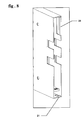
- Fig. 8 shows the open end of a drawer container
- Fig. 9 shows a bag holder in view.
- a pocket holder 2 is pulled out of its drawer container 1
- an extension piece 18 of the pocket holder 2 slides over a sliding surface 19 of the rail 13.
- the pocket holder 2 takes the rail 13 with it, until the rail 13 abuts an end stop 21 of the drawer container 2.
- the pocket carrier 2 with an attachment 22 attached to its end, abuts against a lock 23 attached to the open end of the drawer container.
- Both the end stop 21 and the lock 23 are designed as elastic tongues, which can also be broken off in the case of necessary extensions, since there are similar elements on the extension pieces that perform their functions.
- FIG. 10 shows a fastening band provided with recesses for the pins of drawer containers, which is used to fix drawer containers to one another in any mutual position.
- Fig. 11 shows a fastening system for extensions of drawer containers, bag carriers or attachments with a handle.
- this system consists of elastic tongues 24 with locking teeth 25 at their ends, which alternately point in opposite directions.
- Corresponding openings 26 for the corresponding locking teeth 25 are provided on the counterpart.
- the holder 29 is made of plastic, which is divided into strips in the middle in the area of the opening of the information carriers, which are plastically deformed in various ways in the deep-drawing technique and thus offer a form-fitting hold on the edges of the attached information carriers 27 and 28.
- Fig. 14 shows two such brackets, which are joined by a flexible material to a single sheet. This results in the possibility of the like on one or both brackets additional holding devices for descriptions. to attach.
Landscapes
- Packaging For Recording Disks (AREA)
- Packaging Of Annular Or Rod-Shaped Articles, Wearing Apparel, Cassettes, Or The Like (AREA)
Abstract
Description
In mit umfangreichen Informationen arbeitenden Betrieben besteht die Notwendigkeit, rasch zu einzelnen, schon gespeicherten Informationen zu gelangen, die aus ökonomischen Gründen kompakt aufbewahrt werden müssen. Vielfach sind bei solchen Betrieben ideale Ablageverhältnisse nicht gegeben, weil einfach zusammenhängende Räume nicht zur Verfügung stehen. Auch bei geordneten Ablegevorrichtungen, die flächenhaft organisiert sind, benötigt man für den Zugang verhältnismäßig viele und große Zugangskorridore zu freigestapelten Informationsträgern.In companies that work with extensive information, there is a need to quickly access individual, already stored information that must be kept compact for economic reasons. In many cases, ideal storage conditions do not exist in such companies, because simply connected spaces are not available. Even with orderly filing devices that are organized over a large area, a relatively large number of large access corridors are required to access information piles that have been piled up.
Die Erfindung betrifft einen Speicher für flache , insbesondere scheibenförmige Informationsträger , der aus aufeinander oder nebeneinanander stapelbaren flachen Schubfachbehältern besteht, bei dem der für den Zugang zu den Ablagevorrichtungen benötigte Raum minimal ist, wobei der für die Ablage selbst benötigte Raum optimal ausgenützt werden kann.The invention relates to a memory for flat, in particular disc-shaped information carriers, which consists of stackable flat drawer containers stacked on top of one another or next to one another, in which the space required for access to the storage devices is minimal, the space itself required for the storage being able to be optimally utilized.
Die Speicherung von Informationsträgern in aufeinander und nebeneinander gestapelten Schubfachbehältern ist an sich bekannt. So ist beispielsweise in der EP 0092 666 A1 ein Magnetbandkassettenbehälter beschrieben , der mit einer Anzeigeeinrichtung versehen ist, die erkennen 1äßt , ob der Behälter eine Kassette enthält oder nicht. Eine optimale Nutzung des zur Verfügung stehenden Raumes spielt bei diesem bekannten Kassettenbehälter keine Rolle. Einem speziellen Zweck dient der in der EP 0 059 429 A1 Kassettenspeicher für Bandkassetten kleinerer Abmessungen , die in Auslagen von Geschäften gegenüber Bandkassetten größerer Abmessungen unscheinbar wirken und daher gegenüber den letzteren einen Wettbewerbsnachteil erleiden. Demgemäß werden bei diesem bekannten Speicher mehrere Bandkassetten kleinerer Abmessungen mit Hilfe von Verbindungsstücken zu größeren Einheiten zusammengebaut , die dann die Ausmaße von größeren Bandkassettenspeichern aufweisen. Auch bei dieser bekannten Anordnung werden keine Probleme des Platzbedarfes gelöst.The storage of information carriers in drawer containers stacked on top of and next to one another is known per se. For example, EP 0092 666 A1 describes a magnetic tape cassette container which is provided with a display device which shows whether the container contains a cassette or not. Optimal use of the available space plays no role in this known cassette container.
Erfindungsgemäß wird die optimale Raumausnützung dadurch erzielt, daß die Schubfachbehälter zur Aufnahme von einschiebbaren Taschenträgern dienen, die aus aneinander gereihten , ebenfals flachen Taschen für die Informationsträger bestehen, wobei die Einschubrichtung der Informationsträger senkrecht steht zur Einschubrichtung der Taschenträger in die Schubfachbehälter. Um die Schubfachbehälter zu kompakten , an die vorhandene Raumstruktur anpaßbaren Gebilden zusammenbauen zu können, sind die Schubfachbehälter gemäß einem weiteren Merkmal der Erfindung mit ineinander in Eingriff zu bringenden Zapfen und Ausnehmungen für die Befestigung aneinander oder mittels eines Befestigungsbandes versehen. Nach einem weiteren Merkmal der Erfindung sind die Taschenträger mit Stützschienen versehen , an denen sie mittels eingelassener Rollen gleiten und die zur Abstützung der Taschenträger im ausgezogenen Zustand dienen. Das Wesen der Erfindung besteht darin, daß zu den Schubfachbehältern auch noch in diese einschiebbare Taschenträger vorgesehen sind. Mittels der Taschenträger können die Informationsträger in die Schubfachbehälter nicht nur eingelegt, sondern innerhalb derselben auch noch verschoben werden, nicht nur einzeln , sondern auch gruppenweise, da die Informationsträger hintereinander in mehrere Taschenträger eingelegt werden können.According to the invention, the optimal use of space is achieved in that the drawer containers serve to accommodate insertable pocket carriers which consist of lined up, likewise flat pockets for the information carriers, the direction of insertion of the information carriers being perpendicular to the direction of insertion of the pocket carriers into the drawer containers. In order to be able to assemble the drawer containers to form compact structures that can be adapted to the existing spatial structure, the drawer containers are provided according to a further feature of the invention with interlocking pins and recesses for fastening to one another or by means of a fastening tape. According to a further feature of the invention, the bag carriers are provided with support rails, on which they slide by means of embedded rollers and which serve to support the bag carriers in the extended state. The essence of the invention is that there are also pocket holders which can be inserted into the drawer containers. By means of the pocket carriers, the information carriers can not only be inserted into the drawer containers, but can also be moved within them, not only individually, but also in groups, since the information carriers can be inserted one after the other into several pocket carriers.
Ausführungsbeispiele der Erfindung sind in der Zeichnung dargestellt.
- Fig. 1 zeigt einen
Schubfachbehälter 1 eines erfindungsgemäßen Speichers. - Fig. 2 zeigt eine spezielle Speicheranordnung in einem vorgegebenen Raum.
- Fig.3 zeigt einen freistehenden Stapel.
- Fig. 4 und 5 zeigen Verlängerungen für Schubfachbehälter und Taschenträger sowie ein Ansatzstück mit Handgriff.
- Fig.6 zeigt im Querschnitt einen Schubfachbehälter mit eingeschobenem Taschenträger mit einer Führungsrille und einer Stützschiene.
- Fig.7 zeigt die Stützschiene in Ansicht.
- Fig.8 zeigt das offene Ende eines
Schubfachbehälters 1. - Fig.9 zeigt einen Taschenträger in Seitenansicht.
- Fig. 10 zeigt ein Befestigungsband für die Fixierung von mehreren Schubfachbehältern aneinander.
- Fig.11 zeigt ein Befestigungssystem für Verlängerungen von Schubfachbehältern oder Taschenträgern.
- Fig. 12 bis 14 stellen zusätzliche Halterungen für Informationsträger dar.
- 1 shows a
drawer container 1 of a store according to the invention. - 2 shows a special storage arrangement in a given space.
- Figure 3 shows a free-standing stack.
- 4 and 5 show extensions for drawer containers and bag carriers as well as an extension with a handle.
- Fig. 6 shows in cross section a drawer container with inserted pocket holder with a guide groove and a support rail.
- Fig. 7 shows the support rail in view.
- 8 shows the open end of a
drawer container 1. - Fig. 9 shows a bag carrier in side view.
- 10 shows a fastening tape for fixing several drawer containers to one another.
- Fig. 11 shows a fastening system for extensions of drawer containers or bag carriers.
- 12 to 14 represent additional holders for information carriers.
Der in Fig. 1 gezeigte Kunststoffschubfachbehälter 1 eines erfindungsgemäßen Speichers besitzt an einer Stirnfläche eine Einschuböffnung. In diese ist ein Taschenträger 2 für scheibenförmige Informationsträger 3, insbesondere Compact Discs, in Richtung des Pfeiles 4 einschiebbar. Der Informationsträger 3 ist in eine zugehörige Tasche des Taschenträgers 2 in Richtung des Pfeiles 5 einschiebbar. Die Einschubrichtungen 4 und 5 sind zueinander senkrecht , so dass die eingeschobenen Informationsträger gegen Herausfallen gesichert sind. Durch diese Ausbildung der Taschenträger ist gewährleistet ,daß alle Informationsträger in gleicher Weise zugänglich sind, unabhängig davon, an welcher Stelle innerhalb des Taschenträgers sie abgelegt wurden. Die Anzahl der in einem Taschenträger unterzubringenden Informationsträger hängt von der Länge der Schubfachbehälter 1 ab. Die Schubfachbehälter sind mit ineinander in Eingriff zu bringenden Zapfen 6 und Ausnehmungen für die Befestigung nebeneinander , übereinander oder mit zusätzlichen Halteelementen versehen. Das Wesen der Erfindung besteht darin, daß die Anordnung der Schubfachbehälter den vorgegebenen Raumverhältnissen angepaßt werden kann, wodurch der vorhandene Raum optimal ausgenützt wird, wobei die Zugänglichkeit zu jedem einzelnen Informationsträger unabhängig von seiner Speicherlage gegeben ist. Durch die Anordnung der in die Tiefe greifenden Taschenträger 2 in den Schubfachbehältern 1 sind die nebeneinanander und übereinander angeordneten Taschenträger 2 voneinander in der Bewegung unabhängig. Eine beispielhafte Anordnung von Schubfachbehältern 1 in einem mehrfach unterteilten Raum zeigt Fig.2. Außerdem zeigt Fig.2, daß die Schubfachbehälter 1 sowohl vertikal als auch horizontal gelagert werden können. Die Speicheranordnung kann auch , wie aus der Fig.3 hervorgeht, als frei im Raum auf einem Ständer 7 stehender Stapel ausgebildet sein.The
Durch die unterschiedlichen Raumverhältnisse bedingt, ergibt sich die Notwendigkeit, Schubfachbehälter verschiedener Längen zu verwenden. Demgemäß ergibt sich weiters auch die Notwendigkeit, Taschenträger verschiedener Längen zu verwenden. Die Schubfachbehälter und auch die Taschenträger können entweder in verschiedenen Längen (Grössen) oder aber auch nur in einer Grundgröße vorgefertigt werden und dann durch ansetzbare Verlängerungsstücke auf die geforderte Länge gebracht werden. Fig.4 zeigt einen Schubfachbehälter 1 in der Grundgröße mit einem ansetzbaren Verlängerungsstück 8. In Fig.5 ist ein Taschenträger 2 in der Grundgröße mit einem ebenfalls ansetzbaren Verlängerungsstück 9 und einen Ansatzstück mit Handgriff 10 dargestellt, das zum Ausziehen des Taschenträgers 2 aus dem Schubfachbehälter 1 dient und das außerdem zur Beschriftung und sonstigen (durch Farbgebung) Kennzeichnung verwendbar ist.Due to the different spatial conditions, there is a need to use drawer containers of different lengths. Accordingly, there is also the need to use bag carriers of different lengths. The drawer containers and the bag carriers can either be prefabricated in different lengths (sizes) or only in one basic size and then brought to the required length by attachable extension pieces. 4 shows a
Der Schubfachbehälter 1 hat, wie in Fig.5 und Fig.6 dargestellt, eine nach innen ausgebildete Rille 11, der Taschenträger 2 hat eine komplementär ausgebildete Rille 12. Beide Rillen greifen ineinander und ermöglichen eine glatte Bewegung. Um ein Verkanten des Taschenträgers 2 gegenüber dem Schubfachbehälter 1 auch bei ausgezogenem Taschenträger 2 zu vermeiden, ist zwischen diesen beiden Rillen eine Stützschiene 13 vorgesehen. Fig.6 zeigt im Querschnitt den Taschenträger 2 mit der Führungsrille 12, die mit Gleitrollen 14 besetzt ist, um im Zusammenwirken mit der Schiene 13 innerhalb des Schubfachbehälters 1 eine gegen Verkanten gesicherte Führung zu ermöglichen. Im gleichen Sinne dienen die Rollen 15, die an einer Rillenleiste 16 des Schubfachbehälters 1 angebracht sind. Mit 17 sind weitere am Taschenträger 2 angebrachte Gleitrollen bezeichnet, die eine Abstützung gegenüber dem Schubfachbehälter 1 bewirken. Die Ansicht der Schiene 13 ist in der Fig. 7 dargestellt.The
Fig.8 zeigt das offene Ende eines Schubfachbehälters und Fig.9 zeigt einen Taschenträger in Ansicht. Beim Ausziehen eines Taschenträgers 2 aus seinem Schubfachbehälter 1 gleitet ein Ansatzstück 18 des Taschenträgers 2 über eine Gleitfläche 19 der Schiene 13. Sobald der Taschenträger 2 im Zuge der Ausziehbewegung den Anschlag 20 der Schiene 13 trifft, nimmt der Taschenträger 2 die Schiene 13 solange mit, bis die Schiene 13 an einen Endanschlag 21 des Schubfachbehälters 2 anstößt. Zugleich stößt der Taschenträger 2 mit einem an seinem Ende angebrachten Ansatz 22 gegen eine am offenen Ende des Schubfachbehälters angebrachte Sperre 23. Sowohl der Endanschlag 21 als auch die Sperre 23 sind als elastische Zungen ausgebildet die im Falle von erforderlichen Verlängerungen auch abgebrochen werden können, da sich auf den Verlängerungstücken gleichartige Elemente befinden, die deren Funktionen übernehmen.Fig. 8 shows the open end of a drawer container and Fig. 9 shows a bag holder in view. When a
Fig.10 zeigt ein mit Ausnehmungen für Zapfen von Schubfachbehältern versehenes Befestigungsband, das dazu dient, um Schubfachbehälter in beliebiger gegenseitiger Lage aneinander zu fixieren .10 shows a fastening band provided with recesses for the pins of drawer containers, which is used to fix drawer containers to one another in any mutual position.
Fig.11 zeigt ein Befestigungssystem für Verlängerungen von Schubfachbehältern, Taschenträgern oder Ansatzstücken mit Handgriff. Im einzelnen besteht dieses System aus elastischen Zungen 24 mit an ihrem Ende befindlichen Rastzähnen 25, die abwechselnd nach entgegengesetzten Richtungen weisen. Am Gegenstück sind entsprechende Öffnungen 26 für die entsprechenden Rastzähne 25 vorgesehen.Fig. 11 shows a fastening system for extensions of drawer containers, bag carriers or attachments with a handle. In particular, this system consists of
Zur Aufbewahrung von Informationsträgern ohne eigene Hülle ist es zweckmäßig, je zwei scheibenförmige Informationsträger 27 und 28 an eine gemeinsame Halterung 29 anzubringen, wie in Figuren 12 (Ansicht) und 13 (Querschnitt) dargestellt ist. Die Halterung 29 besteht aus Kunststoff, der in der Mitte im Bereich der Öffnung der Informationsträger in Streifen unterteilt ist, die in Tiefziehtechnik abwechselnd nach verschiedenen Seiten plastisch deformiert sind und so an ihren Rändern für die angesetzten Informationsträger 27 und 28 einen formschlüssigen Halt bieten.To store information carriers without their own casing, it is expedient to attach two disk-shaped
Fig.14 zeigt zwei solche Halterungen, die durch biegsames Material zu einem einzigen Faltblatt zusammengefügt sind. Hierbei ergibt sich die Möglichkeit, an einer oder beiden Halterungen zusätzliche Haltevorrichtungen für Beschreibungen o.dgl. anzubringen.Fig. 14 shows two such brackets, which are joined by a flexible material to a single sheet. This results in the possibility of the like on one or both brackets additional holding devices for descriptions. to attach.
Claims (10)
Applications Claiming Priority (2)
| Application Number | Priority Date | Filing Date | Title |
|---|---|---|---|
| AT67598 | 1998-04-21 | ||
| AT67598A AT405889B (en) | 1998-04-21 | 1998-04-21 | STORAGE FOR FLAT, IN PARTICULAR DISK-SHAPED INFORMATION CARRIERS |
Publications (1)
| Publication Number | Publication Date |
|---|---|
| EP0952584A1 true EP0952584A1 (en) | 1999-10-27 |
Family
ID=3496874
Family Applications (1)
| Application Number | Title | Priority Date | Filing Date |
|---|---|---|---|
| EP99890090A Withdrawn EP0952584A1 (en) | 1998-04-21 | 1999-03-11 | Storage device for flat information carriers, specially in disc form |
Country Status (5)
| Country | Link |
|---|---|
| EP (1) | EP0952584A1 (en) |
| JP (1) | JPH11334779A (en) |
| AT (1) | AT405889B (en) |
| AU (1) | AU2386599A (en) |
| CA (1) | CA2268648A1 (en) |
Cited By (3)
| Publication number | Priority date | Publication date | Assignee | Title |
|---|---|---|---|---|
| FR2884033A1 (en) * | 2005-03-29 | 2006-10-06 | Mick Taimiot | Audio, video and computing data medium e.g. CD, case storage device, has square shaped individual storage units fitted one over another, where pins placed on one of sides of unit are fitted in female housings on one of sides of another unit |
| EP1486977A3 (en) * | 2003-06-11 | 2007-07-18 | FUJIFILM Corporation | Tape cassette storing case |
| WO2007093777A2 (en) * | 2006-02-13 | 2007-08-23 | Motto Design Limited | Improvements in or relating to housings |
Citations (5)
| Publication number | Priority date | Publication date | Assignee | Title |
|---|---|---|---|---|
| EP0059429A1 (en) * | 1981-03-02 | 1982-09-08 | Olympus Optical Co., Ltd. | Tape cassette storage box coupling accessory |
| EP0092666A1 (en) * | 1982-04-28 | 1983-11-02 | idn inventions and development of novelties ag | Magnetic tape cassette case |
| US4426056A (en) * | 1981-03-31 | 1984-01-17 | Shape Inc. | Plate bracket for mounting a cassette box |
| US4557533A (en) * | 1979-11-01 | 1985-12-10 | Koch Richard C | Media storage device |
| WO1992022903A1 (en) * | 1991-06-14 | 1992-12-23 | Luckhurst Anthony Henry Willia | Storage container |
-
1998
- 1998-04-21 AT AT67598A patent/AT405889B/en not_active IP Right Cessation
-
1999
- 1999-03-11 EP EP99890090A patent/EP0952584A1/en not_active Withdrawn
- 1999-04-13 CA CA 2268648 patent/CA2268648A1/en not_active Abandoned
- 1999-04-19 JP JP11118399A patent/JPH11334779A/en active Pending
- 1999-04-20 AU AU23865/99A patent/AU2386599A/en not_active Abandoned
Patent Citations (5)
| Publication number | Priority date | Publication date | Assignee | Title |
|---|---|---|---|---|
| US4557533A (en) * | 1979-11-01 | 1985-12-10 | Koch Richard C | Media storage device |
| EP0059429A1 (en) * | 1981-03-02 | 1982-09-08 | Olympus Optical Co., Ltd. | Tape cassette storage box coupling accessory |
| US4426056A (en) * | 1981-03-31 | 1984-01-17 | Shape Inc. | Plate bracket for mounting a cassette box |
| EP0092666A1 (en) * | 1982-04-28 | 1983-11-02 | idn inventions and development of novelties ag | Magnetic tape cassette case |
| WO1992022903A1 (en) * | 1991-06-14 | 1992-12-23 | Luckhurst Anthony Henry Willia | Storage container |
Cited By (5)
| Publication number | Priority date | Publication date | Assignee | Title |
|---|---|---|---|---|
| EP1486977A3 (en) * | 2003-06-11 | 2007-07-18 | FUJIFILM Corporation | Tape cassette storing case |
| US7316314B2 (en) | 2003-06-11 | 2008-01-08 | Fujifilm Corporation | Tape cassette storing case with stacking ribs |
| FR2884033A1 (en) * | 2005-03-29 | 2006-10-06 | Mick Taimiot | Audio, video and computing data medium e.g. CD, case storage device, has square shaped individual storage units fitted one over another, where pins placed on one of sides of unit are fitted in female housings on one of sides of another unit |
| WO2007093777A2 (en) * | 2006-02-13 | 2007-08-23 | Motto Design Limited | Improvements in or relating to housings |
| WO2007093777A3 (en) * | 2006-02-13 | 2007-10-04 | Motto Design Ltd | Improvements in or relating to housings |
Also Published As
| Publication number | Publication date |
|---|---|
| AU2386599A (en) | 1999-10-28 |
| ATA67598A (en) | 1999-04-15 |
| AT405889B (en) | 1999-12-27 |
| CA2268648A1 (en) | 1999-10-21 |
| JPH11334779A (en) | 1999-12-07 |
Similar Documents
| Publication | Publication Date | Title |
|---|---|---|
| EP0615246A1 (en) | Storage device for compact discs and similar | |
| DE2248408B1 (en) | CONTAINER FOR ACCEPTING A CASSETTE WITH A TAPE-SHAPED RECORDING MEDIUM | |
| DE2027379B2 (en) | Hanging register-like storage device for magnetic tape cassettes | |
| DE8610725U1 (en) | Disk storage | |
| DE3724961C1 (en) | Multi-part receptacle for several disc-shaped recording devices | |
| DE20000007U1 (en) | Multipurpose shelf | |
| EP0085911B1 (en) | Snap-in holder for magnetic tape cassette cases | |
| AT405889B (en) | STORAGE FOR FLAT, IN PARTICULAR DISK-SHAPED INFORMATION CARRIERS | |
| EP0712527B1 (en) | Price-display unit | |
| EP0271651A2 (en) | Device for stocking and displaying packages | |
| DE2811535A1 (en) | EXHIBITION DEVICE FOR PLAYED TAPES | |
| DE4109153C2 (en) | Device for storing CD cassettes | |
| DE9416910U1 (en) | Storage box for archiving a data or sound carrier | |
| WO1983000768A1 (en) | Support-plate for a sound tape cassette intended to be preserved in a casing | |
| EP1135775B1 (en) | Device for storing disc-shaped data carriers | |
| DE9209982U1 (en) | Device for depositing and removing cuboid-shaped objects | |
| DE1231028B (en) | Record holder | |
| DE8912225U1 (en) | Round corner for wall systems | |
| DE19513271C2 (en) | Archiving device for audio and video cassettes | |
| DE9200619U1 (en) | Storage facility for communication and/or information media | |
| DE2625511C3 (en) | Book-shaped cassette made of plastic for holding film or audio tape reels | |
| DE2220287A1 (en) | ARRANGEMENT OF POCKET BOOKS AND DISPLAY SHELF FOR THE SAME | |
| DE8800426U1 (en) | Device for receiving and storing containers | |
| DE8324257U1 (en) | SQUARE CONTAINER | |
| DE8519219U1 (en) | Shelf arrangement, in particular for a mobile shelf system, for magnetic tape cassettes |
Legal Events
| Date | Code | Title | Description |
|---|---|---|---|
| PUAI | Public reference made under article 153(3) epc to a published international application that has entered the european phase |
Free format text: ORIGINAL CODE: 0009012 |
|
| AK | Designated contracting states |
Kind code of ref document: A1 Designated state(s): DE ES FR GB IT NL SE |
|
| AX | Request for extension of the european patent |
Free format text: AL;LT;LV;MK;RO;SI |
|
| AKX | Designation fees paid |
Free format text: DE ES FR GB IT NL SE |
|
| STAA | Information on the status of an ep patent application or granted ep patent |
Free format text: STATUS: THE APPLICATION IS DEEMED TO BE WITHDRAWN |
|
| 18D | Application deemed to be withdrawn |
Effective date: 20000428 |