EP0952441A1 - Method and apparatus to measure sunlight induced fluorescence - Google Patents
Method and apparatus to measure sunlight induced fluorescence Download PDFInfo
- Publication number
- EP0952441A1 EP0952441A1 EP99107749A EP99107749A EP0952441A1 EP 0952441 A1 EP0952441 A1 EP 0952441A1 EP 99107749 A EP99107749 A EP 99107749A EP 99107749 A EP99107749 A EP 99107749A EP 0952441 A1 EP0952441 A1 EP 0952441A1
- Authority
- EP
- European Patent Office
- Prior art keywords
- sun
- light guide
- fluorescence
- detectors
- light
- Prior art date
- Legal status (The legal status is an assumption and is not a legal conclusion. Google has not performed a legal analysis and makes no representation as to the accuracy of the status listed.)
- Granted
Links
Images


Classifications
-
- G—PHYSICS
- G01—MEASURING; TESTING
- G01N—INVESTIGATING OR ANALYSING MATERIALS BY DETERMINING THEIR CHEMICAL OR PHYSICAL PROPERTIES
- G01N21/00—Investigating or analysing materials by the use of optical means, i.e. using sub-millimetre waves, infrared, visible or ultraviolet light
- G01N21/62—Systems in which the material investigated is excited whereby it emits light or causes a change in wavelength of the incident light
- G01N21/63—Systems in which the material investigated is excited whereby it emits light or causes a change in wavelength of the incident light optically excited
- G01N21/64—Fluorescence; Phosphorescence
- G01N21/6486—Measuring fluorescence of biological material, e.g. DNA, RNA, cells
-
- G—PHYSICS
- G01—MEASURING; TESTING
- G01N—INVESTIGATING OR ANALYSING MATERIALS BY DETERMINING THEIR CHEMICAL OR PHYSICAL PROPERTIES
- G01N21/00—Investigating or analysing materials by the use of optical means, i.e. using sub-millimetre waves, infrared, visible or ultraviolet light
- G01N21/62—Systems in which the material investigated is excited whereby it emits light or causes a change in wavelength of the incident light
- G01N21/63—Systems in which the material investigated is excited whereby it emits light or causes a change in wavelength of the incident light optically excited
- G01N21/64—Fluorescence; Phosphorescence
- G01N21/645—Specially adapted constructive features of fluorimeters
- G01N21/6456—Spatial resolved fluorescence measurements; Imaging
-
- G—PHYSICS
- G01—MEASURING; TESTING
- G01N—INVESTIGATING OR ANALYSING MATERIALS BY DETERMINING THEIR CHEMICAL OR PHYSICAL PROPERTIES
- G01N21/00—Investigating or analysing materials by the use of optical means, i.e. using sub-millimetre waves, infrared, visible or ultraviolet light
- G01N21/62—Systems in which the material investigated is excited whereby it emits light or causes a change in wavelength of the incident light
- G01N21/63—Systems in which the material investigated is excited whereby it emits light or causes a change in wavelength of the incident light optically excited
- G01N21/64—Fluorescence; Phosphorescence
- G01N2021/6417—Spectrofluorimetric devices
- G01N2021/6421—Measuring at two or more wavelengths
-
- G—PHYSICS
- G01—MEASURING; TESTING
- G01N—INVESTIGATING OR ANALYSING MATERIALS BY DETERMINING THEIR CHEMICAL OR PHYSICAL PROPERTIES
- G01N21/00—Investigating or analysing materials by the use of optical means, i.e. using sub-millimetre waves, infrared, visible or ultraviolet light
- G01N21/62—Systems in which the material investigated is excited whereby it emits light or causes a change in wavelength of the incident light
- G01N21/63—Systems in which the material investigated is excited whereby it emits light or causes a change in wavelength of the incident light optically excited
- G01N21/64—Fluorescence; Phosphorescence
- G01N2021/6417—Spectrofluorimetric devices
- G01N2021/6426—Determining Fraunhofer lines
-
- G—PHYSICS
- G01—MEASURING; TESTING
- G01N—INVESTIGATING OR ANALYSING MATERIALS BY DETERMINING THEIR CHEMICAL OR PHYSICAL PROPERTIES
- G01N2201/00—Features of devices classified in G01N21/00
- G01N2201/06—Illumination; Optics
- G01N2201/061—Sources
- G01N2201/0616—Ambient light is used
Definitions
- the invention relates to a method for deriving sun-excited fluorescent light from radiance measurements and devices for carrying out the method.
- reflection measurements are often used to determine the condition of the vegetation.
- the light reflected by the vegetation is detected in more or less narrow channels.
- measurements with spectrometers are carried out a few meters above the ground.
- the procedure for determining a reflection spectrum must be considered: First, the light reflected by a white standard (i.e. an area with a known degree of reflection of almost 100%) is measured. Then the light reflected back from the examination object is detected. These two measurements are shown in FIG. 7, from which the reflection spectrum in FIG. 6 was calculated by forming the ratio and multiplying it by the reflection spectrum of the white standard.
- a white standard i.e. an area with a known degree of reflection of almost 100%
- chlorophyll fluorescence is used to characterize the state of a photosynthetic apparatus. Therefore a method was developed to derive the fluorescence from the reflection signal. This method is described below.
- LASER published “Remote Sensing of Environment” year 1994, issue 47, pages 10 to 17. With these active methods, however, it is not the fluorescent light that is caused by the solar radiation, but only the additionally generated fluorescent light that is measured. Only statements about the fluorescence quantum yield can therefore be made.
- the object of the invention is to further develop a method for deriving sun-excited fluorescent light from radiance measurements without the aid of an additional light source, and devices for carrying out the method for detecting sun-excited fluorescence, in particular chlorophyll fluorescence from green plants from a distance of several meters or for imaging Detect fluorescence, in particular chlorophyll fluorescence of green plants.
- the method according to the invention is based on the “filling” of broadband atmospheric absorption bands in the reflection signal by fluorescent light. It is assumed here that the radiance L ⁇ at the detector is composed as follows:
- R denotes the unknown reflectance of the substance to be investigated, which is assumed to be spectrally independent in the spectral range under investigation.
- L 0 ⁇ the radiance of sunlight on the object
- L fluorescence is the fluorescence beam density, which is also assumed to be spectrally independent
- T ⁇ the transmittance of the atmosphere between the object and the sensor
- L air ⁇ denotes the radiance of the so-called "air light", ie the light scattered directly from the atmosphere between the object and the sensor to the sensor.
- the radiance is measured at at least two closely spaced wavelengths, namely a radiance within an atmospheric absorption band and another outside the atmospheric absorption band, so that the spectral independence of the reflectance R and the fluorescence beam density L fluorescence is ensured.
- the advantages of the invention lie in the fact that an additional light source can be dispensed with, and thus it is possible to detect the sun-excited fluorescence light even from larger areas.
- the detection system has lower requirements with regard to spectral resolution.
- a spectral resolution of 10 nm is sufficient in the region of the O 2 A absorption band around 762 nm. This in turn enables the use of less sensitive detectors or measurements over larger distances. Furthermore, a fluorescence measurement in the spectral range from 650nm to 800nm, which is important for the detection of chlorophyll fluorescence, is made possible.
- image points of non-fluorescent objects are used to determine the radiation density conditions on the ground and the influence of the atmosphere.
- the fluorescence beam density L is for two detectors 0 1 and L 0 2nd a relative calibration is sufficient. If the absolute value of the fluorescence beam density is to be determined, the two fluorescence beam densities L 1 and L 2 detecting detectors must be absolutely calibrated. Otherwise, a relative calibration of the detectors with each other is sufficient.
- L 1 direction equal to k 3 ⁇ L fluorescence . If the radiance L 1 is plotted against the radiance L 2 of non-fluorescent objects, then k 1 corresponds to the slope and k 2 to the intercept of the best-fit line. The fluorescence beam density of fluorescent objects can then be calculated from the above equation.
- k 3 cannot be derived solely from the measurements of the beam densities L 1 and L 2 .
- the fluorescence beam density can therefore only be derived in relative units. Soil measurements must be available for an absolute statement, or the transmissivity of the atmosphere T 1 and T 2 must be known from other measurements or simulation calculations.
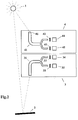
- FIG. 1 An exemplary embodiment of a device for carrying out the method according to the invention with regard to fluorescence detection over a distance of several meters in the region of the O 2 A absorption band around 762 nm is shown in FIG.
- a lower detection unit 3 in FIG. 2 receives light emitted by a measurement object 2 illuminated by the sun 1 with the aid of a light guide 31.
- This light guide 31 consists of several individual multimode fibers 32, 23, which are statistically distributed over two detectors 34 and 35. This ensures that any image information is blurred and the two detectors 34 and 35 "see" the same areas of the measurement object.
- An upper detection unit 4 in FIG. 2 for detecting irradiated light has basically the same structure as the detection unit 3, namely a light guide 41 and two detectors 44 and 45.
- a diffuser 46 is arranged in front of the light guide 41 in order to increase its acceptance angle enlarge.
- interference bandpass filters 32 and 42 In front of the detectors 34 and 44 there are interference bandpass filters 32 and 42 with a central wavelength of 752nm and a bandwidth of 5nm for spectral selection.
- Interference band-pass filters 33 and 43 are likewise arranged in front of the detectors 35 and 45 and have a central wavelength of 762 nm with a bandwidth of likewise 5 nm.
- An accuracy of ⁇ 2nm is sufficient for the location of the central wavelength and the bandwidth of the interference filter. It is only important that the spectral transmission characteristics of filters 32 and 42 or 33 and 43 match.
- the fluorescence kinetics of the photosynthesis apparatus of a green plant was recorded in order to demonstrate that fluorescence was actually detected.
- measurements were made with the aid of an active measurement method that is common today, PAM fluorometry.
- the measuring distance was approximately 1 cm, an area of 0.2 cm 2 being recorded.
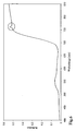
- FIG. 3 shows the time course of the reflected radiance of vegetation measured with the aid of the spectrometer in (L1) or before (L2) the O2A absorption band.
- the time curve of the fluorescence derived from this according to Eq. (2) and measured with a PAM fluorometer is plotted in FIG. The two measurements agree very well despite the different sized measuring area.
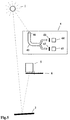
- FIG. 5 schematically shows an embodiment of a device for imaging fluorescence.
- the lower detection unit is replaced by a CCD camera 5.
- a CCD camera 5 In order to avoid the expense of a second CCD camera, only one CCD camera with an upstream filter wheel 6 is provided.
- the interference bandpass filters which are not shown in detail, are accommodated on the filter wheel 6 so that it is possible to switch between the two detection channels.
- a method is thus created to derive sun-excited fluorescence from reflection measurements. This makes it possible to derive the fluorescence from passive measurements using simple spectrometers. This in turn enables the use of aircraft or satellite-borne spectrometers for large-scale detection of the chlorophyll fluorescence and thus the photosynthetic state of the vegetation.
Abstract
Description
Die Erfindung betrifft ein Verfahren zum Ableiten sonnenangeregten Fluoreszenzlichts aus Strahldichtemessungen sowie Einrichtungen zum Durchführen des Verfahrens.The invention relates to a method for deriving sun-excited fluorescent light from radiance measurements and devices for carrying out the method.
Zur Ermittlung des Zustandes der Vegetation werden in der Fernerkundung häufig Reflexionsmessungen eingesetzt. Dabei wird das von der Vegetation reflektierte Licht in mehr oder weniger schmalen Kanälen detektiert. Zur Verifikation und um den Einfluß der Atmosphäre auszuschließen, werden hierbei auch Messungen mit Spektrometern wenige Meter über dem Boden durchgeführt.In remote sensing, reflection measurements are often used to determine the condition of the vegetation. The light reflected by the vegetation is detected in more or less narrow channels. For verification and to exclude the influence of the atmosphere, measurements with spectrometers are carried out a few meters above the ground.
Im Rahmen einer Meßkampagne wurden beispielsweise Messungen dieser Art an Weizenkulturen durchgeführt. Ein typisches Reflexionsspektrum zeigt Fig.6. Auffällig ist ein - durch einen Kreis gekennzeichneter - Peak bei 762nm im sogenannten Infrarotplateau. Dieser Peak tritt bei Labormessungen mit künstlicher Beleuchtung nie auf.As part of a measurement campaign, measurements of this type were carried out on wheat crops, for example. A typical reflection spectrum is shown in Fig. 6. What is striking is a - marked by a circle - peak at 762nm in the so-called infrared plateau. This peak never occurs in laboratory measurements with artificial lighting.
Um seine Ursache zu klären, muß die Vorgehensweise bei der Ermittlung eines Reflexionsspektrums betrachtet werden: Zunächst wird das von einem Weißstandard (d.h. einer Fläche mit bekanntem Reflexionsgrad von beinahe 100%) reflektierte Licht gemessen. Dann wird das vom Untersuchungsobjekt zurückgestrahlte Licht erfaßt. In Fig.7 sind diese beiden Messungen dargestellt, aus denen das Reflexionsspektrum in Fig.6 durch Verhältnisbildung und Multiplikation mit dem Reflexionsspektrum des Weißstandards berechnet wurde.In order to clarify its cause, the procedure for determining a reflection spectrum must be considered: First, the light reflected by a white standard (i.e. an area with a known degree of reflection of almost 100%) is measured. Then the light reflected back from the examination object is detected. These two measurements are shown in FIG. 7, from which the reflection spectrum in FIG. 6 was calculated by forming the ratio and multiplying it by the reflection spectrum of the white standard.
In Fig.7 ist deutlich die O2A-Aosorptionsbande der Atmosphäre bei 762nm zu erkennen. Da die Messungen hier aufgrund der niedrigeren Signale einen größeren relativen Fehler aufweisen, wurden als Ursache für den Peak Meßfehler verantwortlich gemacht. Der Peak sollte dann jedoch statistisch verteilt einmal nach oben und einmal nach unten gerichtet sein.7 clearly shows the O 2 A aosorption band of the atmosphere at 762 nm. Since the measurements here have a larger relative error due to the lower signals, were blamed as the cause of the peak measurement error. However, the peak should then be statistically distributed once upwards and once downwards.
Bei weiteren Messungen zeigte sich jedoch, daß der Peak immer nach oben gerichtet war. Es mußte also ein systematischer Fehler vorliegen. Da er jedoch nur bei grüner Vegetation auftrat, konnte die Ursache nur Chlorophyll-Fluoreszenz sein.However, further measurements showed that the peak was always directed upwards. So there had to be a systematic error. However, since it only occurred with green vegetation, the cause could only be chlorophyll fluorescence.
In der Biologie wird die Chlorophyll-Fluoreszenz zur Charakterisierung des Zustandes eines Photosyntheseapparates eingesetzt. Daher wurde eine Methode entwickelt, die Fluoreszenz aus dem Reflexionssignal abzuleiten. Diese Methode wird im folgenden beschrieben.In biology, chlorophyll fluorescence is used to characterize the state of a photosynthetic apparatus. Therefore a method was developed to derive the fluorescence from the reflection signal. This method is described below.
Um das von bestimmten Stoffen, insbesondere grünen Pflanzenteilen, unter Tageslichtbedingungen emittierte Fluoreszenzlicht zu messen, werden bisher im allgemeinen aktive Meßmethoden eingesetzt. Hierbei wird der zu untersuchende Stoff zusätzlich zur Beleuchtung durch die Sonne mit einer gepulsten oder modulierten Lichtquelle bestrahlt. Das durch dieses Licht zusätzlich erzeugte Fluoreszenzlicht wird mit Hilfe der Lock-In-Meßtechnik detektiert. Für kurze Entfernungen und Punktmessungen werden als Lichtquellen LEDs eingesetzt (Zeitschrift "Rev. Sci. Instrum." Jahrgang 1975, Band 46, Heft 5, S. 538 bis 542).In order to measure the fluorescent light emitted by certain substances, in particular green parts of plants, under daylight conditions, active measuring methods have hitherto generally been used. In addition to being illuminated by the sun, the substance to be examined is irradiated with a pulsed or modulated light source. The fluorescence light additionally generated by this light is detected with the aid of the lock-in measurement technique. LEDs are used as light sources for short distances and point measurements (magazine "Rev. Sci. Instrum." Volume 1975,
Für größere Distanzen und bildhafte Erfassung ist man auf den Einsatz von LASER angewiesen (Zeitschrift "Remote Sensing of Environment" Jahrgang 1994, Heft 47, Seiten 10 bis 17). Bei diesen aktiven Methoden wird jedoch nicht das durch die Sonnenbestrahlung hervorgerufene, sondern nur das zusätzlich erzeugte Fluoreszenzlicht gemessen. Es können also nur Aussagen über die Fluoreszenzquantenausbeute gemacht werden.For longer distances and image acquisition, you have to use LASER (magazine "Remote Sensing of Environment" year 1994, issue 47,
Der Erfindung liegt die Aufgabe zugrunde, ohne Zuhilfenahme einer zusätzlichen Lichtquelle ein Verfahren zum Ableiten sonnenangeregten Fluoreszenzlichts aus Strahldichtemessungen weiter zu entwickeln sowie Einrichtungen zur Durchführung des Verfahrens zum Erfassen sonnenangeregter Fluoreszenz, insbesondere Chlorophyll-Fluoreszenz grüner Pflanzen aus einer Entfernung von mehreren Metern bzw. zum bildhaften Erfassen von Fluoreszenz, insbesondere Chlorophyll-Fluoreszenz grüner Pflanzen vorzusehen.The object of the invention is to further develop a method for deriving sun-excited fluorescent light from radiance measurements without the aid of an additional light source, and devices for carrying out the method for detecting sun-excited fluorescence, in particular chlorophyll fluorescence from green plants from a distance of several meters or for imaging Detect fluorescence, in particular chlorophyll fluorescence of green plants.
Gemäß der Erfindung ist dies bei einem Verfahren nach dem Oberbegriff des Anspruchs 1 durch die Merkmale in dessen kennzeichnenden Teil erreicht. Eine vorteilhafte Weiterbildung ist Gegenstand der Anspruchs 2. Ferner sind Einrichtungen zum Durchführen des Verfahrens zum Erfassen sonnenangeregter Fluoreszenz, insbesondere von Chlorophyll-Fluoreszenz grüner Pflanzen über eine Entfernung von mehreren Metern bzw. bildhaften Erfassen einer Fluoreszenz, mit den Merkmalen im kennzeichnenden Teil des Anspruchs 3 bzw. 4 geschaffen.According to the invention, this is achieved in a method according to the preamble of claim 1 by the features in its characterizing part. An advantageous development is the subject of
Das erfindungsgemäße Verfahren beruht auf dem "Auffüllen" breitbandiger atmosphärischer Absorptionsbanden im Reflexionssignal durch Fluoreszenzlicht. Hierbei ist davon ausgegangen, daß sich die Strahldichte Lλ am Detektor, wie folgt, zusammensetzt:
Hierbei ist mit R der unbekannte Reflexionsgrad des zu untersuchenden Stoffes bezeichnet, der im untersuchten Spektralbereich als spektral unabhängig angenommen wird. Ferner sind mit L ![]()
![]()
![]()
![]()
Gemessen werden die Strahldichten bei mindestens zwei dicht beieinander liegenden Wellenlängen, nämlich eine Strahldichte innerhalb einer atmosphärischen Absorptionsbande und eine weitere außerhalb der atmosphärischen Absorptionsbande, so daß die spektrale Unabhängigkeit des Reflexionsgrades R und der Fluoreszenzstrahldichte L Fluoreszenz gewährleistet ist.The radiance is measured at at least two closely spaced wavelengths, namely a radiance within an atmospheric absorption band and another outside the atmospheric absorption band, so that the spectral independence of the reflectance R and the fluorescence beam density L fluorescence is ensured.
Zur Detektion der Chlorophyll-Fluoreszenz bei 762nm ist beispielsweise ein Abstand der beiden Meßwellenlängen von bis zu 10nm möglich. Die Kenntnis der exakten Lage der Wellenlängen ist unkritisch. Die einzige Bedingung, die erfüllt sein muß, um das entstehende Gleichungssystem zu lösen, sind unterschiedliche Strahldichten des eingestrahlten Sonnenlichts bei den verwendeten Meßwellenlängen. Diese Bedingung ist im Bereich der atmosphärischen Absorptionsbanden von Wasserdampf und molekularem Sauerstoff zwischen 660nm und 1000nm erfüllt.For the detection of chlorophyll fluorescence at 762nm, for example, a distance of up to 10nm between the two measuring wavelengths is possible. Knowing the exact location of the wavelengths is not critical. The only condition that must be met in order to solve the resulting system of equations are different radiance of the incident sunlight at the measuring wavelengths used. This condition is met in the range of the atmospheric absorption bands of water vapor and molecular oxygen between 660nm and 1000nm.
In den meisten Fällen ist die Vorausetzung eines spektral unabhängigen Reflexionsgrades R und einer spektral unabhängiger Fluoreszenzstrahldichte L Fluoreszenz zu umgehen, indem gemäß einer vorteilhaften Weiterbildung des erfindungsgemäßen Verfahrens statt einer Messung außerhalb der Absorptionsbande, je eine Messung zu beiden Seiten der Absorptionsbande vorgenommen wird. Auf diese Weise werden bei der gleichen Wellenlänge zwei Messungen mit stark unterschiedlichen einfallenden Strahldichten erhalten und es kann somit die Fluoreszenzstrahldichte bestimmt werden.In most cases, the requirement of a spectrally independent reflectance R and a spectrally independent fluorescence beam density L fluorescence must be circumvented, in accordance with an advantageous development of the method according to the invention, instead of a measurement outside the absorption band, one measurement is carried out on both sides of the absorption band. In this way, two measurements with very different incident values are made at the same wavelength Obtain beam densities and the fluorescence beam density can thus be determined.
Gegenüber den bisher angewendeten Fluoreszenzmeßverfahren liegen die Vorteile bei der Erfindung darin, daß auf eine zusätzliche Lichtquelle verzichtet werden kann und damit ein Erfassen des sonnenangeregten Fluoreszenzlichts auch von größeren Flächen ermöglicht wird. Außerdem werden an das Detektionssystem geringere Anforderungen hinsichtlich der spektralen Auflösung gestellt.Compared to the previously used fluorescence measurement methods, the advantages of the invention lie in the fact that an additional light source can be dispensed with, and thus it is possible to detect the sun-excited fluorescence light even from larger areas. In addition, the detection system has lower requirements with regard to spectral resolution.
So ist beispielsweise im Bereich der O2A-Absorptionsbande um 762nm eine spektrale Auflösung von 10nm ausreichend. Dies ermöglicht wiederum den Einsatz weniger empfindlicher Detektoren bzw. Messungen über größere Distanzen. Weiterhin wird eine Fluoreszenzmessung im für eine Detektion der Chlorophyll-Fluoreszenz wichtigen Spektralbereich von 650nm bis 800nm ermöglicht.For example, a spectral resolution of 10 nm is sufficient in the region of the O 2 A absorption band around 762 nm. This in turn enables the use of less sensitive detectors or measurements over larger distances. Furthermore, a fluorescence measurement in the spectral range from 650nm to 800nm, which is important for the detection of chlorophyll fluorescence, is made possible.
Gemäß einer vorteilhaften Weiterbildung der Erfindung werden, um sonnenangeregtes Fluoreszenzlicht aus mit Hilfe flugzeug- oder satellitengetragener abbildender Spektrometer gewonnenen Bilddaten abzuleiten, zum Bestimmen der Strahldichteverhältnisse am Boden sowie des Einflusses der Atmosphäre Bildpunkte nicht fluoreszierender Objekte verwendet.According to an advantageous development of the invention, in order to derive sun-excited fluorescent light from image data obtained with the aid of imaging spectrometers carried by airplanes or satellites, image points of non-fluorescent objects are used to determine the radiation density conditions on the ground and the influence of the atmosphere.
Nachfolgend wird die Erfindung anhand der Zeichnungen im einzelnen erläutert. Es zeigen:
- Fig.1
- einen Graphen in Form einer Geraden, auf welcher Strahldichten von nicht-fluoreszierenden Objekten aufgetragen sind, während in der Halbebene oberhalb der Geraden Strahldichten fluoreszierender Objekte aufgetragen sind;
- Fig.2
- eine erste Ausführungsform einer Einrichtung für eine Fluoreszenzdetektion über nur einige Meter Entfernung im Bereich der O2A-Absorptionsbande;
- Fig.3
- den zeitlichen Verlauf von mit Hilfe eines Spektrometers gemessenen reflektierten Strahldichten in bzw. vor der O2A-Absorptionsbande;
- Fig.4
- einen aus Fig.3 nach Gl.(2) abgeleiteten sowie einen mit einem PAM-Fluorometer gemessenen, zeitlichen Verlauf einer Fluoreszenz, wobei auf der Abszisse die Zeit in Sekunden (s) und auf der Ordinate die Fluoreszenzstrahldichte in mW/(m2nm sr) aufgetragen sind;
- Fig.5
- eine bevorzugte Ausführungsform einer Einrichtung zum Durchführen des Verfahrens zur bildhaften Erfassung der Fluoreszenz;
- Fig.6
- einen Graphen eines typischen Reflexionsspektrums, wobei auf der Abszisse die Wellenlänge in nm und auf der Ordinate die Reflexion aufgetragen sind, und
- Fig.7
- Graphen, durch welche ein berechnetes Reflexionsspektrum nach Fig.6 durch Verhältnisbildung und Multiplikation und ein Reflexionsspektrum eines Weißstandards wiedergegeben sind.
- Fig. 1
- a graph in the form of a straight line, on which radiations of non-fluorescent objects are plotted, while in the half-plane above the straight line radiations of fluorescent objects are plotted;
- Fig. 2
- a first embodiment of a device for fluorescence detection only a few meters away in the region of the O 2 A absorption band;
- Fig. 3
- the time course of reflected beam densities measured with the aid of a spectrometer in or before the O 2 A absorption band;
- Fig. 4
- one derived from FIG. 3 according to Eq. (2) and one with a PAM fluorometer, a temporal course of fluorescence, the time in seconds (s) on the abscissa and the fluorescence beam density in mW / (m 2 nm on the ordinate sr) are applied;
- Fig. 5
- a preferred embodiment of a device for performing the method for imaging fluorescence;
- Fig. 6
- a graph of a typical reflection spectrum, with the wavelength in nm on the abscissa and the reflection on the ordinate, and
- Fig. 7
- Graphs by which a calculated reflection spectrum according to FIG. 6 is represented by ratio formation and multiplication and a reflection spectrum of a white standard.
Je nach Aerosolgehalt kann der Einfluß der Atmosphäre zwischen Meßobjekt und Sensor bei Meßabständen von bis zu einigen hundert Metern vernachlässigt werden. Das bedeutet: Transmissionsgrad ![]()
![]()

![]()
![]()
Wie die Auswertegleichung (2) zeigt, ist für zwei Detektoren, die Fluoreszenzstrahldichten L ![]()
![]()
![]()
![]()
In der Fernerkundung kann der Einfluß der Atmosphäre zwischen Objekt und Sensor nicht vernachlässigt werden. Weiterhin ist es in den meisten Fällen nicht möglich, auf das Objekt eingestrahltes Sonnenlicht direkt zu messen. Daher muß auf nachfolgend beschriebenes Verfahren zurückgegriffen werden. Aus Gl. (1) ergibt sich folgende Auswertegleichung:
In Fig.1 sind auf der Ordinate eine Strahldichte L 1 und auf der Abszisse eine Strahldichte L 2 aufgetragen. Die Strahldichten nicht fluoreszierender Objekte liegen auf einer Geraden. Die fluoreszierender Objekte liegen in der oberen Halbebene. Dabei ist der Abstand in der Ordinaten- bzw.1 shows a radiance L 1 on the ordinate and a radiance L 2 on the abscissa. The radiance of non-fluorescent objects lies on a straight line. The fluorescent objects are in the upper half-plane. The distance in the ordinate or
L1-Richtung gleich k3·L Fluoreszenz . Wird also die Strahldichte L1 über der Strahldichte L2 von nicht fluoreszierenden Objekten aufgetragen, so entspricht k1 der Steigung und k2 dem Achsenabschnitt der Ausgleichsgeraden. Die Fluoreszenzstrahldichte fluoreszierender Objekte läßt sich dann aus obiger Gleichung berechnen.L 1 direction equal to k 3 · L fluorescence . If the radiance L 1 is plotted against the radiance L 2 of non-fluorescent objects, then k 1 corresponds to the slope and k 2 to the intercept of the best-fit line. The fluorescence beam density of fluorescent objects can then be calculated from the above equation.
Jedoch läßt sich k3 nicht allein aus den Messungen der Strahldichten L1 und L2 ableiten. Die Fluoreszenzstrahldichte ist somit nur in relativen Einheiten ableitbar. Für eine Absolutangabe müssen Bodenmessungen vorliegen, bzw. es muß der Transmissionsgrad der Atmosphäre T1 und T2 durch andere Messungen bzw. Simulationsrechnungen bekannt sein.However, k 3 cannot be derived solely from the measurements of the beam densities L 1 and L 2 . The fluorescence beam density can therefore only be derived in relative units. Soil measurements must be available for an absolute statement, or the transmissivity of the atmosphere T 1 and T 2 must be known from other measurements or simulation calculations.
Ein Ausführungsbeispiel einer Einrichtung zum Durchführen des erfindungsgemäßen Verfahrens hinsichtlich einer Fluoreszenzdetektion über mehrere Meter Entfernung im Bereich der O2A-Absorptionsbande um 762nm ist in Fig.2 dargestellt. Eine in Fig.2 untere Detektionseinheit 3 nimmt von einem von der Sonne 1 beleuchteten Meßobjekt 2 emittiertes Licht mit Hilfe eines Lichtleiters 31 auf. Dieser Lichtleiter 31 besteht aus mehreren einzelnen Multimodefasern 32, 23, die statistisch auf zwei Detektoren 34 und 35 verteilt sind. Dadurch wird erreicht, daß jegliche Bildinformation verwischt wird und die beiden Detektoren 34 und 35 dieselben Bereiche des Meßobjektes "sehen".An exemplary embodiment of a device for carrying out the method according to the invention with regard to fluorescence detection over a distance of several meters in the region of the O 2 A absorption band around 762 nm is shown in FIG. A
Eine in Fig.2 obere Detektionseinheit 4 zum Erfassen von eingestrahltem Licht hat prinzipiell den gleichen Aufbau wie die Detektionseinheit 3, nämlich einen Lichtleiter 41 und zwei Detektoren 44 und 45. Zusätzlich ist jedoch ein Diffusor 46 vor dem Lichtleiter 41 angeordnet, um dessen Akzeptanzwinkel zu vergrößern.An
Vor den Detektoren 34 und 44 sind Interferenzbandpaßfilter 32 und 42 mit einer Zentralwellenlänge von 752nm und einer Bandbreite von 5nm zur spektralen Selektion angeordnet. Vor den Detektoren 35 und 45 sind ebenfalls Interferenzbandpaßfilter 33 und 43 angeordnet, die eine Zentralwellenlänge von 762 nm bei einer Bandbreite von ebenfalls 5nm besitzen. Für die Lage der Zentralwellenlänge, sowie der Bandbreite der Interferenzfilter ist eine Genauigkeit von ±2nm ausreichend. Wichtig ist nur die Übereinstimmung der spektralen Transmissionscharakteristiken der Filter 32 und 42 bzw. 33 und 43.In front of the
Zum Nachweis der Funktionsfähigkeit dieses Gerätes wurde es mit Hilfe eines Spektrometers simuliert. Die spektrale Selektion der Kanäle wurde dabei mittels eines Gitters bewerkstelligt. (Im Prinzip hätte jedes beliebige Spektrometer mit ausreichender spektraler Auflösung verwendet werden können.) Die Messung erfolgte über eine Entfernung von etwa einem Meter. Dies entsprach einem Meßfleckdurchmesser von 20cm.To demonstrate the functionality of this device, it was simulated using a spectrometer. The spectral selection of the channels was accomplished using a grating. (In principle, any spectrometer with sufficient spectral resolution could have been used.) The measurement was carried out over a distance of approximately one meter. This corresponded to a measuring spot diameter of 20 cm.
Um nachzuweisen, daß tatsächlich die Fluoreszenz erfaßt wird, wurde die Fluoreszenzkinetik des Photosyntheseapparates einer grünen Pflanze (Kautskyeffekt) aufgenommen. Gleichzeitig wurden Messungen mit Hilfe eines heute üblichen aktiven Meßverfahrens, der PAM-Fluorometrie, gemacht. Der Meßabstand betrug dabei ca. lcm, wobei eine Fläche von 0.2cm2 erfaßt wurde.The fluorescence kinetics of the photosynthesis apparatus of a green plant (Kautsky effect) was recorded in order to demonstrate that fluorescence was actually detected. At the same time, measurements were made with the aid of an active measurement method that is common today, PAM fluorometry. The measuring distance was approximately 1 cm, an area of 0.2 cm 2 being recorded.
In Fig.3 ist der zeitliche Verlauf der mit Hilfe des Spektrometers gemessenen reflektierten Strahldichten von Vegetation in (L1) bzw. vor (L2) der O2A-Absorptionsbande wiedergegeben. In Fig.4 ist der daraus nach Gl.(2) abgeleitete und mit einem PAM-Fluorometer gemessene zeitliche Verlauf der Fluoreszenz aufgetragen. Die beiden Messungen stimmen trotz der unterschiedlich großen Meßfläche sehr gut überein.3 shows the time course of the reflected radiance of vegetation measured with the aid of the spectrometer in (L1) or before (L2) the O2A absorption band. The time curve of the fluorescence derived from this according to Eq. (2) and measured with a PAM fluorometer is plotted in FIG. The two measurements agree very well despite the different sized measuring area.
In Fig.5 ist schematisch eine Ausführungsform einer Einrichtung zur bildhaften Erfassung der Fluoreszenz wiedergegeben. Hierbei ist die untere Detektionseinheit durch eine CCD-Kamera 5 ersetzt. Um den Aufwand einer zweiten CCD-Kamera zu vermeiden, ist nur eine CCD-Kamera mit vorgeschaltetem Filterrad 6 vorgesehen. Die - im einzelnen nicht näher dargestellten - Interferenzbandpaßfilter sind hierbei auf dem Filterrad 6 untergebracht, so daß zwischen den beiden Detektionskanälen umgeschaltet werden kann.5 schematically shows an embodiment of a device for imaging fluorescence. The lower detection unit is replaced by a
Gemäß der Erfindung ist somit ein Verfahren geschaffen, um sonnenangeregte Fluoreszenz aus Reflexionsmessungen abzuleiten. Dadurch ist es möglich, die Fluoreszenz aus passiven Messungen mit einfachen Spektrometern abzuleiten. Dies wiederum ermöglicht den Einsatz von flugzeug- bzw. satellitengetragenen Spektrometern zur großflächigen Erfassung der Chlorophyll-Fluoreszenz und damit des photosynthetischen Zustands der Vegetation.According to the invention, a method is thus created to derive sun-excited fluorescence from reflection measurements. This makes it possible to derive the fluorescence from passive measurements using simple spectrometers. This in turn enables the use of aircraft or satellite-borne spectrometers for large-scale detection of the chlorophyll fluorescence and thus the photosynthetic state of the vegetation.
- 11
- SonneSun
- 22nd
- MeßobjektTarget
- 33rd
- DetektionseinheitDetection unit
- 3131
- LichtleiterLight guide
- 32, 3332, 33
- InterferenzbandpaßfilterInterference bandpass filter
- 34, 3534, 35
- DetektorenDetectors
- 44th
- DetektionseinheitDetection unit
- 4141
- LichtleiterLight guide
- 42,4342.43
- InterferenzbandpaßfilterInterference bandpass filter
- 44, 4544, 45
- DetektorenDetectors
- 4646
- DiffusorDiffuser
- 55
- CCD-KameraCCD camera
- 66
- FilterradFilter wheel
Claims (4)
eine erste Detektoreinheit (3), mittels welcher von einem von der Sonne (1) beleuchteten Meßobjekt (2) emittiertes Licht aufgenommen wird, einen aus mehreren einzelnen Multimodefasern bestehenden Lichtleiter (31), der an seinem dem Meßobjekt abgewandten Ende gabelförmig in zwei gleich große Abschnitte aufgeteilt ist, und den beiden Lichtleiter-Abschnitten nachgeordnete Detektoren (34, 35) aufweist, wobei zwischen den beiden Abschnitten des Lichtleiters (31) und den Detektoren (34, 35) Interferenzbandpaßfilter (32, 33) vorgesehen sind, und
eine zweite Detektoreinheit (4), mittels welcher eingestrahltes Sonnenlicht aufgenommen wird, einen entsprechend dem Lichtleiter (31) der ersten Detektoreinheit (3) ausgebildeten Lichtleiter (41) und dessen beiden ebenfalls gabelförmig ausgebildeten Endabschnitten nachgeordnete Detektoren (44, 45) aufweist, wobei an dem zur Sonne hin ausgerichteten Ende des Lichtleiters (41) ein Diffusor (46) vorgeschaltet ist, und wobei zwischen den beiden Abschnitten des Lichtleiters (41) und den nachgeordneten Detektoren ebenfalls Interferenzbandpaßfilter (42, 43) vorgesehen sind.Device for carrying out the method according to claim 1 for detecting sun-excited fluorescence, in particular chlorophyll fluorescence from green plants over a distance of several meters, characterized in that
a first detector unit (3), by means of which light emitted by a measurement object (2) illuminated by the sun (1) is received, a light guide (31) consisting of several individual multimode fibers, which at its end facing away from the measurement object is fork-shaped into two of the same size Sections is divided and has detectors (34, 35) arranged downstream of the two light guide sections, interference bandpass filters (32, 33) being provided between the two sections of the light guide (31) and the detectors (34, 35), and
a second detector unit (4), by means of which incident sunlight is recorded, a light guide (41) designed in accordance with the light guide (31) of the first detector unit (3) and both of which are also fork-shaped Detectors (44, 45) arranged downstream from end sections, a diffuser (46) being connected upstream at the end of the light guide (41) oriented towards the sun, and interference bandpass filters (42) between the two sections of the light guide (41) and the downstream detectors , 43) are provided.
eine Detektoreinheit (4) mit einem aus mehreren einzelnen Multimodefasern bestehenden Lichtleiter (41), diesem nachgeordneten Detektoren (44, 45) und dazwischen vorgesehenen Interferenzbandpaßfiltern (42, 43) zum Aufnehmen von eingestrahltem Sonnenlicht, und
eine CCD-Kamera (5) mit vorgeschaltetem Filterrad (6) zum Aufnehmen des von einem von der Sonne (1) beleuchteten Meßobjekts (2) emittierten Lichts.Device for carrying out the method according to one of claims 1 or 3 for the pictorial detection of sun-excited fluorescence, in particular chlorophyll fluorescence of green plants, characterized by
a detector unit (4) with a light guide (41) consisting of several individual multimode fibers, detectors (44, 45) arranged after this and interference bandpass filters (42, 43) provided therebetween for receiving incident sunlight, and
a CCD camera (5) with an upstream filter wheel (6) for recording the light emitted by a measurement object (2) illuminated by the sun (1).
Applications Claiming Priority (2)
| Application Number | Priority Date | Filing Date | Title |
|---|---|---|---|
| DE19817843A DE19817843B4 (en) | 1998-04-22 | 1998-04-22 | Method for deriving sun-excited fluorescent light from radiance measurements |
| DE19817843 | 1998-04-22 |
Publications (2)
| Publication Number | Publication Date |
|---|---|
| EP0952441A1 true EP0952441A1 (en) | 1999-10-27 |
| EP0952441B1 EP0952441B1 (en) | 2002-07-03 |
Family
ID=7865348
Family Applications (1)
| Application Number | Title | Priority Date | Filing Date |
|---|---|---|---|
| EP99107749A Expired - Lifetime EP0952441B1 (en) | 1998-04-22 | 1999-04-19 | Method for measuring sunlight induced fluorescence |
Country Status (3)
| Country | Link |
|---|---|
| US (1) | US6329660B1 (en) |
| EP (1) | EP0952441B1 (en) |
| DE (1) | DE19817843B4 (en) |
Cited By (2)
| Publication number | Priority date | Publication date | Assignee | Title |
|---|---|---|---|---|
| WO2012001171A1 (en) * | 2010-07-02 | 2012-01-05 | Georg Fritzmeier Gmbh & Co. Kg | Measurement system and method for determining a nitrogen content in plants |
| CN107238435A (en) * | 2017-06-07 | 2017-10-10 | 江苏省无线电科学研究所有限公司 | Solar radiation flux Vertical Profile survey meter |
Families Citing this family (6)
| Publication number | Priority date | Publication date | Assignee | Title |
|---|---|---|---|---|
| CN100338444C (en) * | 2003-06-13 | 2007-09-19 | 上海爱普特仪器有限公司 | Laser intensity adjusting device |
| CN104897674B (en) * | 2015-06-08 | 2017-09-01 | 云南农业大学 | A kind of method of simulated determination sylvan life shade plant to hot spot response characteristic |
| CN105486673B (en) * | 2016-01-27 | 2020-03-10 | 北京师范大学 | Chlorophyll fluorescence automatic monitoring system |
| CN105548122B (en) * | 2016-01-27 | 2020-04-17 | 北京师范大学 | Chlorophyll fluorescence time-sharing monitoring system |
| IT201900020174A1 (en) * | 2019-10-31 | 2021-05-01 | Consiglio Nazionale Ricerche | CALIBRATION DEVICE FOR MEASURING THE FLUORESCENCE OF CHLOROPHYLL INDUCED BY SUNLIGHT |
| AU2021287075A1 (en) * | 2020-06-12 | 2023-01-19 | Newsouth Innovations Pty Limited | Outdoor photoluminescence imaging of photovoltaic modules |
Citations (6)
| Publication number | Priority date | Publication date | Assignee | Title |
|---|---|---|---|---|
| US3598994A (en) * | 1968-09-19 | 1971-08-10 | Perkin Elmer Corp | Method and apparatus for sensing fluorescent substances |
| US4671662A (en) * | 1985-06-18 | 1987-06-09 | Atlantic Richfield Company | Luminescense and reflectance detection radiometer with changeable optical assembly |
| US4708475A (en) * | 1983-06-30 | 1987-11-24 | Atlantic Richfield Company | Portable luminescence sensor |
| US5062713A (en) * | 1989-09-06 | 1991-11-05 | The Dow Company | Method for determining the residence time distribution of a polymer extruder |
| US5298741A (en) * | 1993-01-13 | 1994-03-29 | Trustees Of Tufts College | Thin film fiber optic sensor array and apparatus for concurrent viewing and chemical sensing of a sample |
| US5567947A (en) * | 1995-06-01 | 1996-10-22 | Aerodyne Research, Inc. | Spectral line discriminator for passive detection of fluorescence |
-
1998
- 1998-04-22 DE DE19817843A patent/DE19817843B4/en not_active Expired - Fee Related
-
1999
- 1999-04-19 EP EP99107749A patent/EP0952441B1/en not_active Expired - Lifetime
- 1999-04-20 US US09/294,357 patent/US6329660B1/en not_active Expired - Fee Related
Patent Citations (6)
| Publication number | Priority date | Publication date | Assignee | Title |
|---|---|---|---|---|
| US3598994A (en) * | 1968-09-19 | 1971-08-10 | Perkin Elmer Corp | Method and apparatus for sensing fluorescent substances |
| US4708475A (en) * | 1983-06-30 | 1987-11-24 | Atlantic Richfield Company | Portable luminescence sensor |
| US4671662A (en) * | 1985-06-18 | 1987-06-09 | Atlantic Richfield Company | Luminescense and reflectance detection radiometer with changeable optical assembly |
| US5062713A (en) * | 1989-09-06 | 1991-11-05 | The Dow Company | Method for determining the residence time distribution of a polymer extruder |
| US5298741A (en) * | 1993-01-13 | 1994-03-29 | Trustees Of Tufts College | Thin film fiber optic sensor array and apparatus for concurrent viewing and chemical sensing of a sample |
| US5567947A (en) * | 1995-06-01 | 1996-10-22 | Aerodyne Research, Inc. | Spectral line discriminator for passive detection of fluorescence |
Non-Patent Citations (1)
| Title |
|---|
| "PLANT STRESS DETECTION BY REMOTE MEASUREMENT OF FLUORESCENCE", APPLIED OPTICS, vol. 19, no. 19, 1 October 1980 (1980-10-01), pages 3287 - 3289, XP000611046, ISSN: 0003-6935 * |
Cited By (3)
| Publication number | Priority date | Publication date | Assignee | Title |
|---|---|---|---|---|
| WO2012001171A1 (en) * | 2010-07-02 | 2012-01-05 | Georg Fritzmeier Gmbh & Co. Kg | Measurement system and method for determining a nitrogen content in plants |
| CN107238435A (en) * | 2017-06-07 | 2017-10-10 | 江苏省无线电科学研究所有限公司 | Solar radiation flux Vertical Profile survey meter |
| CN107238435B (en) * | 2017-06-07 | 2018-06-12 | 江苏省无线电科学研究所有限公司 | Solar radiation flux Vertical Profile survey meter |
Also Published As
| Publication number | Publication date |
|---|---|
| DE19817843B4 (en) | 2006-06-08 |
| EP0952441B1 (en) | 2002-07-03 |
| US6329660B1 (en) | 2001-12-11 |
| DE19817843A1 (en) | 1999-11-04 |
Similar Documents
| Publication | Publication Date | Title |
|---|---|---|
| EP0534166B1 (en) | Procedure and apparatus for the quantitative determination of optic active substances | |
| DE2902776C2 (en) | ||
| EP0076356B1 (en) | Method and device for the measurement of a component absorbing an infrared, near infrared, visible or ultraviolet radiation in a mixture | |
| DE69535012T2 (en) | Method and apparatus for measuring the concentration of absorbing components in a scattering medium | |
| EP0174496B1 (en) | Procedure for measuring the radiation wavelength and the wavelength-corrected radiation power of monochromatical light-sources and arrangement for carrying out this procedure | |
| DE4008280A1 (en) | Indicating ice etc. on road surface - using IR detector and halogen lamp source with beam modulator and narrow bandpass filter | |
| EP0777119A2 (en) | Apparatus for light reflection measurements | |
| DE4209886A1 (en) | ABSORPTION SPECTRUM CORRECTION AND SPECTROMETER WORKING WITH IT | |
| DE19601873C2 (en) | Gas analyzer | |
| EP0030610A1 (en) | Method and device for quantitative determination of optically active substances | |
| DE1939982C3 (en) | Method and device for the determination of fluorescence excited by sunlight | |
| DE3741940C2 (en) | Color sensor | |
| DE2511771B2 (en) | ARRANGEMENT FOR DETERMINING THE ALCOHOL CONTENT IN THE BLOOD | |
| DE602004004638T2 (en) | Calibration of peak patterns | |
| EP0952441A1 (en) | Method and apparatus to measure sunlight induced fluorescence | |
| DE3541165A1 (en) | DEVICE FOR CONTINUOUSLY DETERMINING CONCENTRATION CHANGES IN MIXTURES | |
| DE2130331B2 (en) | METHOD AND DEVICE FOR DETERMINING THE CONCENTRATIONS OF THE COMPONENTS OF A MIXTURE CONSISTING OF TWO GASES AND SMOKE | |
| DE102011117678A1 (en) | Sensor for checking value documents | |
| DE2207298A1 (en) | Radiant energy analyzer for atomic absorption analysis | |
| DE4240301A1 (en) | ||
| EP0902272A2 (en) | Atomic absorption spectrometer | |
| DE3208737A1 (en) | OPTICAL MULTI-BEAM GAS DETECTOR | |
| DE102017130988B4 (en) | DEVICES AND METHODS FOR UTILIZING THE PHOTOACOUSTIC EFFECT | |
| EP0123672A2 (en) | Method for the determination of the mass of absorbing parts in a sample, and device for carrying out said method | |
| DE3539977C2 (en) |
Legal Events
| Date | Code | Title | Description |
|---|---|---|---|
| PUAI | Public reference made under article 153(3) epc to a published international application that has entered the european phase |
Free format text: ORIGINAL CODE: 0009012 |
|
| AK | Designated contracting states |
Kind code of ref document: A1 Designated state(s): FR GB |
|
| AX | Request for extension of the european patent |
Free format text: AL;LT;LV;MK;RO;SI |
|
| 17P | Request for examination filed |
Effective date: 19991217 |
|
| AKX | Designation fees paid |
Free format text: FR GB |
|
| REG | Reference to a national code |
Ref country code: DE Ref legal event code: 8566 |
|
| 17Q | First examination report despatched |
Effective date: 20010110 |
|
| GRAG | Despatch of communication of intention to grant |
Free format text: ORIGINAL CODE: EPIDOS AGRA |
|
| GRAG | Despatch of communication of intention to grant |
Free format text: ORIGINAL CODE: EPIDOS AGRA |
|
| GRAH | Despatch of communication of intention to grant a patent |
Free format text: ORIGINAL CODE: EPIDOS IGRA |
|
| RTI1 | Title (correction) |
Free format text: METHOD FOR MEASURING SUNLIGHT INDUCED FLUORESCENCE |
|
| GRAH | Despatch of communication of intention to grant a patent |
Free format text: ORIGINAL CODE: EPIDOS IGRA |
|
| GRAA | (expected) grant |
Free format text: ORIGINAL CODE: 0009210 |
|
| AK | Designated contracting states |
Kind code of ref document: B1 Designated state(s): FR GB |
|
| GBT | Gb: translation of ep patent filed (gb section 77(6)(a)/1977) |
Effective date: 20020703 |
|
| ET | Fr: translation filed | ||
| PLBE | No opposition filed within time limit |
Free format text: ORIGINAL CODE: 0009261 |
|
| STAA | Information on the status of an ep patent application or granted ep patent |
Free format text: STATUS: NO OPPOSITION FILED WITHIN TIME LIMIT |
|
| 26N | No opposition filed |
Effective date: 20030404 |
|
| PGFP | Annual fee paid to national office [announced via postgrant information from national office to epo] |
Ref country code: GB Payment date: 20070425 Year of fee payment: 9 |
|
| PGFP | Annual fee paid to national office [announced via postgrant information from national office to epo] |
Ref country code: FR Payment date: 20070418 Year of fee payment: 9 |
|
| GBPC | Gb: european patent ceased through non-payment of renewal fee |
Effective date: 20080419 |
|
| REG | Reference to a national code |
Ref country code: FR Ref legal event code: ST Effective date: 20081231 |
|
| PG25 | Lapsed in a contracting state [announced via postgrant information from national office to epo] |
Ref country code: FR Free format text: LAPSE BECAUSE OF NON-PAYMENT OF DUE FEES Effective date: 20080430 |
|
| PG25 | Lapsed in a contracting state [announced via postgrant information from national office to epo] |
Ref country code: GB Free format text: LAPSE BECAUSE OF NON-PAYMENT OF DUE FEES Effective date: 20080419 |