EP0952274A1 - Roof ventilating element and roof covering - Google Patents
Roof ventilating element and roof covering Download PDFInfo
- Publication number
- EP0952274A1 EP0952274A1 EP99107923A EP99107923A EP0952274A1 EP 0952274 A1 EP0952274 A1 EP 0952274A1 EP 99107923 A EP99107923 A EP 99107923A EP 99107923 A EP99107923 A EP 99107923A EP 0952274 A1 EP0952274 A1 EP 0952274A1
- Authority
- EP
- European Patent Office
- Prior art keywords
- roof
- ventilation element
- covering
- eaves
- cover
- Prior art date
- Legal status (The legal status is an assumption and is not a legal conclusion. Google has not performed a legal analysis and makes no representation as to the accuracy of the status listed.)
- Withdrawn
Links
Images

Classifications
-
- E—FIXED CONSTRUCTIONS
- E04—BUILDING
- E04D—ROOF COVERINGS; SKY-LIGHTS; GUTTERS; ROOF-WORKING TOOLS
- E04D13/00—Special arrangements or devices in connection with roof coverings; Protection against birds; Roof drainage; Sky-lights
- E04D13/17—Ventilation of roof coverings not otherwise provided for
- E04D13/178—Ventilation of roof coverings not otherwise provided for on the eaves of the roof
Definitions
- Such a roof ventilation element and such a roof covering have become known, for example, from DE-OS 35 01 773 A1.
- the present invention is therefore based on the object of improving the fastening of roof ventilation elements.
Abstract
Description
Die vorliegende Erfindung betrifft ein Dachlüftungselement, das zwischen Dacheindeckungsplatten und der darunterliegenden Dachkonstruktion verlegbar ist, mit einem Grundprofil, von dessen Oberseite verformbare, an eine Dacheindeckungsplatte anlegbare Elemente aufragen und an dessen Unterseite ein Fußelement ausgebildet ist, das an einer auf der Dachkonstruktion anbringbaren, formstabilen Dachabdeckung lösbar befestigt werden kann. Die Erfindung bezieht sich auch auf eine formstabile Dachabdeckung zur Verbindung mit dem vorgenannten Dachlüftungselement.The present invention relates to a roof ventilation element that can be installed between roofing panels and the underlying roof structure, with a basic profile, from the top of which deformable elements that can be applied to a roofing panel, and on the underside of which a foot element is formed that is dimensionally stable on an attachable to the roof structure Roof cover can be detachably attached. The invention also relates to a dimensionally stable roof covering for connection to the aforementioned roof ventilation element.
Ein derartiges Dachlüftungselement und eine derartige Dachabdeckung sind beispielsweise durch die DE-OS 35 01 773 A1 bekanntgeworden.Such a roof ventilation element and such a roof covering have become known, for example, from DE-OS 35 01 773 A1.
Dachlüftungselemente dienen der Unterlüftung von Dächern und weisen entsprechende Profile auf, so daß die Luft zwischen den Dacheindeckungsplatten und der darunterliegenden Dachkonstruktion hindurchströmen kann. Die Dachlüftungselemente verhindern auch den Schmutzeintritt in diesen Dachbereich. Die Dachlüftungselemente sind derart ausgebildet, daß der unterlüftete Dachbereich unzugänglich für Kleingetier ist.Roof ventilation elements are used to ventilate roofs and have corresponding profiles so that the air can flow between the roof covering panels and the roof structure underneath. The roof ventilation elements also prevent dirt from entering this roof area. The roof ventilation elements are designed such that the ventilated roof area is inaccessible to small animals.
Die Dachlüftungselemente werden zwischen den Dacheindeckungsplatten (Dachpfannen) und weiteren Teilen der Dachkonstruktion (Dachlatten, Dachbahnen) angebracht. Das Fußelement des bekannten Dachlüftungselements kann nur in Längsrichtung des Dachlüftungselements in eine seitlich offene Längsnut der Dachabdeckung (Traufbrett) eingeschoben werden. Die Ausbildung der Nut verteuert die Herstellungskosten und erschwert die Befestigung sich lang erstreckender Dachlüftungselemente, weil diese nur von der Seite eingeschoben werden können. Diese Erschwerung tritt insbesondere dann auf, wenn ein Dachlüftungselement in der Mitte einer Dachabdeckung fixiert werden soll.The roof ventilation elements are installed between the roof covering panels (roof tiles) and other parts of the roof structure (roof battens, roofing sheets). The foot element of the known roof ventilation element can only be inserted into a laterally open longitudinal groove in the roof covering (eaves board) in the longitudinal direction of the roof ventilation element. The formation of the groove increases the cost of production and makes it difficult to attach long roof ventilation elements because they can only be inserted from the side. This complication occurs in particular when a roof ventilation element is to be fixed in the middle of a roof covering.
Der vorliegenden Erfindung liegt daher die Aufgabe zugrunde, die Befestigung von Dachlüftungselementen zu verbessern.The present invention is therefore based on the object of improving the fastening of roof ventilation elements.
Diese Aufgabe wird erfindungsgemäß durch ein Dachlüftungselement mit einem Grundprofil gelöst, dessen Fußelement quer zur Längsrichtung des Grundprofils in eine an der Dacheindeckung ausgebildete Ausnehmung oder Nut eingeschoben und in dieser eingeschoben Stellung an der Dachabdeckung durch Verrastmittel ortfest fixierbar sind.This object is achieved according to the invention by a roof ventilation element with a basic profile, the foot element of which is inserted transversely to the longitudinal direction of the basic profile into a recess or groove formed on the roof covering and into this inserted position on the roof cover can be fixed in place by locking means.
Unter einer Dachabdeckung wird vorliegend eine plane, abkantbare, dünne Auflage auf Teile der Dachkonstruktion verstanden, die zum Abdecken oder Abdichten von Teilen des Dachbereichs geeignet ist.In the present case, a roof covering is understood to mean a flat, foldable, thin support on parts of the roof structure that is suitable for covering or sealing parts of the roof area.
Die Befestigung des Dachlüftungselements an Dachabdeckungen ist leicht handhabbar, so daß der Handwerker das Dachlüftungselement einfach im Dachbereich anbringen kann. Die Anbringung bereitet keine Anpassungsprobleme des Dachlüftungselements an Dacheindeckungsplatten, weil die elastischen Elemente leicht an die verschiedensten Positionen der Dacheindeckungsplatten anlegbar sind. Die Dachabdeckung definiert eine Basis, mit der das Dachlüftungselement anschließend mit Hilfe der Befestigungsmittel verbunden wird. Die Dachabdeckung kann beispielsweise an der Dachkonstruktion aufgenagelt oder mit dieser verklebt werden. Das Dachlüftungselement kann unabhängig von der Lage der Dachlatten oder Trauflatten überall dort angebracht werden, wo eine Dachabdeckung verlegt ist, die eine formstabile Unterlage zur Befestigung des Dachlüftungselements bereit stellt.The attachment of the roof ventilation element to roof covers is easy to handle, so that the craftsman can easily attach the roof ventilation element in the roof area. The attachment does not pose any problems of adaptation of the roof ventilation element to roof covering panels, because the elastic elements can easily be applied to the various positions of the roof covering panels. The roof covering defines a base with which the roof ventilation element is then connected using the fastening means. The roof cover can, for example, be nailed to the roof structure or glued to it. Regardless of the position of the roof battens or eaves battens, the roof ventilation element can be attached wherever a roof covering is laid, which provides a dimensionally stable base for fastening the roof ventilation element.
Das Dachlüftungselement kann beispielsweise als Trauflüftungselement ausgestaltet sein. In diesem Fall läßt sich das Dachlüftungselement in Längsrichtung der Traufe mit einer Dachabdeckung verbinden, um die Unterlüftung des Daches im Bereich der Traufe zu ermöglichen. Das Dachlüftungselement kann aber auch im Bereich von Dachkehlen oder anderen Übergangsbereichen des Daches zu aufragenden Bauteile an Dachabdeckungen angebracht werden, um diesen Bereich des Daches besser unterlüften zu können.The roof ventilation element can, for example, be designed as an eave ventilation element. In this case, the roof ventilation element can be connected to a roof covering in the longitudinal direction of the eaves in order to allow the roof to be ventilated in the area of the eaves. However, the roof ventilation element can also be attached to roof covers in the area of roof fillets or other transition areas of the roof to projecting components, in order to be able to better ventilate this area of the roof.
Bei einer bevorzugten Ausführungsform ist die Ausnehmung an Vorsprüngen oder Sockeln der Seitenfläche der Dachabdeckung ausgebildet. Es entsteht eine teilweise unterbrochene Nut zum Einschieben des Fußelements. Daher kann das Fußelement leicht fixiert werden und gleichzeitig wird bei der Ausbildung einer "Nut" Material gespart. Das Fußelement ist in Ausnehmungen einsetzbar, die an Vorsprüngen, Sockeln oder dergleichen der Seitenfläche der Dachabdeckung ausgebildet sind. Hierbei ist eine Ausnehmung in die Vorsprünge oder Sockel integriert, so daß das Fußelement nicht in der Seitenfläche, wie bei der ersten Variante, sondern auf der Seitenfläche oder oberhalb der Seitenfläche angeordnet ist. Die Seitenfläche kann dünnwandig ausgebildet sein, weil die Nut zur Aufnahme des Fußelements nicht in die Seitenfläche integriert ist.In a preferred embodiment, the recess is formed on projections or bases of the side surface of the roof covering. A partially interrupted groove is created for inserting the foot element. Therefore, the foot element can be easily fixed and at the same time material is saved in the formation of a "groove". The foot element can be used in recesses which are formed on projections, bases or the like of the side surface of the roof covering. Here, a recess is integrated in the projections or base, so that the foot element is not arranged in the side surface, as in the first variant, but on the side surface or above the side surface. The side surface can be thin-walled because the groove for receiving the foot element is not integrated in the side surface.
Bei einer Ausführungsform sind die Verrastmittel durch einen Absatz an der Oberseite der Dachabdeckung ausgebildet, der das Fußelement in der eingeschobenen Stellung hintergreift. Bei einer anderen Ausführungsform sind die Verrastmittel durch einen Klipp (Klemme, Klammer oder dergleichen) ausgebildet, der an der Dachabdeckung befestigbar ist und das Fußelement hintergreift. Vorteilhafterweise ist es möglich, das Dachlüftungselement durch einen Rastverschluß oder Schnappverschluß (Verrastmittel) schnell mit der Dachabdeckung zu verbinden. Der Rastverschluß kann auch wieder gelöst werden, um das Dachlüftungselement gegen ein anderes Dachlüftungselement auszutauschen. Dies kann insbesondere notwendig werden, wenn die an die Dacheindeckungsplatten anlegbaren elastischen Elemente beschädigt oder aber nicht für diesen Dachbereich geeignet sind. Die elastischen Elemente können insbesondere ein Traufkamm mit einzelnen elastischen Fingern oder aber auch eine Bürste mit elastischen Bürstenfäden sein.In one embodiment, the locking means are formed by a shoulder on the top of the roof covering, which engages behind the foot element in the inserted position. In another embodiment, the locking means are formed by a clip (clamp, clip or the like) which can be fastened to the roof covering and engages behind the foot element. It is advantageously possible to quickly connect the roof ventilation element to the roof cover by means of a snap lock or snap lock (locking means). The snap lock can also be released again in order to replace the roof ventilation element with another roof ventilation element. This can be necessary in particular if the elastic elements that can be placed on the roofing panels are damaged or are not suitable for this roof area. The elastic elements can in particular an eaves comb with individual elastic Fingers or a brush with elastic brush threads.
Der Klipp kann einstückig und schwenkbar an der Dachabdeckung vorhanden sein, so daß ein zusätzliches, separates Bauteil eingespart werden kann. Alternativ kann der Klipp ein separates Bauteil sein, das bei Beschädigung ausgetauscht werden kann.The clip can be provided in one piece and pivoted on the roof covering, so that an additional, separate component can be saved. Alternatively, the clip can be a separate component that can be replaced if damaged.
Vorzugsweise bildet das Grundprofil eine integrierte Dachlatte mit Belüftungsöffnungen. Das Grundprofil kann an der Dachabdeckung derart angebracht werden, daß auf dem Grundprofil eine Dacheindeckungsplatte belüftet aufliegen kann. Das Fußelement kann ein Steg, eine Fußleiste oder ein anderer profilierter Abschnitt des Grundprofils sein, der sich in eine entsprechend Komplementär ausgebildete Nut verrastend einsetzen läßt.The basic profile preferably forms an integrated roof batten with ventilation openings. The basic profile can be attached to the roof covering in such a way that a roof covering plate can lie on the basic profile in a ventilated manner. The foot element can be a web, a baseboard or another profiled section of the base profile, which can be inserted in a correspondingly complementary groove.
Eine andere Form der lösbaren Befestigung kann darin bestehen, daß an der Unterseite des Grundprofils Zapfen mit von der Außenumfangsfläche der Zapfen vorstehenden Absätzen ausgebildet sind, wobei die Zapfen in Durchgangslöcher der Dachabdeckung unter einem Hintergriff der Durchgangslöcher durch die Absätze einsteckbar sind. Der Zapfen und die Absätze können elastisch ausgebildet sein, die die Randbereiche der Durchgangslöcher nach dem Einstecken des Zapfens hintergreifen können. Dies stellt ebenso eine ausreichend stabile und dennoch lösbare Verbindung von Dachlüftungselement und Dachabdeckung dar.Another form of releasable fastening can consist in that pegs are formed on the underside of the base profile with shoulders projecting from the outer peripheral surface of the pegs, the pegs being insertable into the through holes in the roof covering under the rear of the through holes. The pin and the shoulders can be elastic, which can engage behind the edge regions of the through holes after the pin has been inserted. This also represents a sufficiently stable, yet detachable connection between the roof ventilation element and the roof cover.
Die Unterseite des Dachlüftungselements einer weiteren Ausführungsform ist auf der den Dacheindeckungsplatten zugewandten Seitenfläche der Dachabdeckung aufklebbar. Die Klebeverbindung kann ebenfalls erfindungsgemäß wieder gelöst werden. Denkbar ist es, die Seitenfläche der Dachabdeckung mit einem Klebe- oder Haftstreifen zu versehen, der nachträglich auf die Seitenfläche aufgebracht werden kann oder aber bereits integriert an dieser vorhanden ist.The underside of the roof ventilation element of a further embodiment can be glued on the side surface of the roof covering facing the roof covering panels. The adhesive connection can also be solved again according to the invention. It is conceivable to provide the side surface of the roof covering with an adhesive or adhesive strip which can be applied subsequently to the side surface or is already integrated on it.
Die Dachabdeckung kann unterschiedlich ausgebildet sein. Vorteilhaft ist es, wenn die Dachabdeckung ein Traufbrett ist. Das Traufbrett kann an der Trauflatte befestigt werden, um den Bereich zwischen Trauflatte und Dachrinne zu überbrücken. Eine derartige Dachabdeckung ist notwendig, weil die Dachrinne nur über einzelne Rinnenhalter mit der Trauflatte verbunden ist und sich daher eine Beabstandung der Dachrinne von der Trauflatte ergibt. Dieses meist im Dachbereich vorhandene und zwingend notwendige Dachelement wird erfindungsgemäß als Dachabdeckung verwendet, an der ein Trauflüftungselement lösbar befestigt werden kann.The roof cover can be designed differently. It is advantageous if the roof covering is an eaves board. The eaves board can be attached to the eaves batten to bridge the area between the eaves batten and the gutter. Such a roof covering is necessary because the gutter is connected to the eaves slat only via individual gutter brackets and therefore there is a spacing of the gutter from the eaves slat. This roof element, which is usually present in the roof area and is absolutely necessary, is used according to the invention as a roof covering to which an eaves ventilation element can be detachably attached.
Die Dachabdeckung kann auch ein in Kehlbereichen des Daches verlegbares Dichtungselement sein. Dieses Dichtungselement dichtet Anschlußbereiche der Dacheindeckungsplatten zu einem von der Dachkonstruktion aufragenden Gebäudeteil ab. In diesen Dachbereichen ist diese Dachabdeckung meist ebenfalls zwingend notwendig, so daß das erfindungsgemäße Dachlüftungselement vorteilhafterweise an diesen bereits vorhandenen Dachabdeckungen lösbar montiert werden kann.The roof covering can also be a sealing element that can be laid in the valley areas of the roof. This sealing element seals the connection areas of the roof covering panels to a part of the building that rises from the roof structure. In these roof areas, this roof covering is usually also absolutely necessary, so that the roof ventilation element according to the invention can advantageously be detachably mounted on these already existing roof covers.
Bekannte Dachabdeckungen im Trauf- oder Kehlbereich werden daher mit einer zusätzlichen Funktion ausgestattet, nämlich ein Dachlüftungselement lösbar zu halten. Daher kann das Dachlüftungselement einerseits schnell montiert werden und andererseits diese kritischen Dachbereiche gut lüftend abschließen.Known roof covers in the eaves or throat area are therefore equipped with an additional function, namely to hold a roof ventilation element detachably. Therefore, the roof ventilation element can be quickly installed on the one hand and on the other hand, these critical roof areas are well ventilated.
Die Anpassung von Dachlüftungselement und Dachabdeckung an unterschiedlichste Dachbereiche kann noch weiter optimiert werden, wenn die Dachabdeckung aus einem ersten Teil zur Befestigung an der Dachkonstruktion und Halterung des Dachlüftungselements und einem zweiten Teil zur Abdeckung von Teilen der Dachkonstruktion zusammengesetzt, wobei der erste Teil mit zweiten Teil biegsam verbunden ist. Die beiden Teile der Dachabdeckung können unter beliebigen Winkeln gegeneinander ausgerichtet werden, die auf Übergangsbereiche am Dach abgestimmt werden können.The adaptation of the roof ventilation element and roof covering to a wide variety of roof areas can be further optimized if the roof covering is composed of a first part for fastening to the roof structure and mounting of the roof ventilation element and a second part for covering parts of the roof structure, the first part being composed of a second part is flexibly connected. The two parts of the roof cover can be aligned against each other at any angle that can be matched to transition areas on the roof.
Bevorzugt ist, daß der erste und zweite Teil aus einem starren Material und der Verbindungsbereich der Teile aus einem biegsamen Material besteht. Der erste starre Teil kann einen Regenschutz bilden, während der zweite starre Teil eine stabile Befestigungsunterlage für das Dachlüftungselement bildet. Der biegsame Mittelteil sorgt für die eine Verformbarkeit und flexible Einsetzbarkeit der Dachabdeckung. Als Werkstoffe kommen harte Kunststoffe für die äußeren Teile und weiche Kunststoffe für den Mittelteil in Betracht.It is preferred that the first and second parts consist of a rigid material and the connection area of the parts consists of a flexible material. The first rigid part can form a rain protection, while the second rigid part forms a stable fastening base for the roof ventilation element. The flexible middle section ensures that the roof covering is deformable and flexible. Hard plastics for the outer parts and soft plastics for the middle part can be considered as materials.
Weitere Merkmale und Vorteile der Erfindung ergeben sich aus der nachfolgenden Beschreibung zweier Ausführungsbeispiele der Erfindung anhand der Zeichnung, die erfindungswesentliche Einzelheiten zeigt, und aus den Ansprüchen. Die einzelnen Merkmale können je einzeln für sich oder zu mehreren in beliebiger Kombination bei einer Ausführungsform der Erfindung verwirklicht sein.Further features and advantages of the invention result from the following description of two exemplary embodiments of the invention with reference to the drawing, which shows details essential to the invention, and from the claims. The individual features can be implemented individually or in any combination in any combination in one embodiment of the invention.
Es zeigt:It shows:
- Fig. 1Fig. 1
- einen Querschnitt durch einen Traufbereich eines Daches, an dem ein Trauflüftungselement montiert ist;a cross section through an eaves area of a roof on which an eaves ventilation element is mounted;
- Fig. 2Fig. 2
- eine perspektivische Darstellung der Verbindung des Trauflüftungslements nach Fig. 1 Mit einem Traufbrett;a perspective view of the connection of the eaves ventilation element according to FIG. 1 with an eaves board;
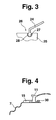
- Fig. 3Fig. 3
- eine Seitenansicht eines Teils eines anderen Trauflüftungselements;a side view of part of another eaves ventilation element;
- Fig. 4Fig. 4
- eine Befestigung des Trauflüftungselements am Traufbrett.fastening the eaves ventilation element to the eaves board.
Die Erfindung ist in den Figuren schematisch dargestellt, so daß die wesentlichen Merkmale der Erfindung gut zu erkennen sind. Die Darstellungen sind nicht notwendigerweise maßstäblich zu verstehen.The invention is shown schematically in the figures, so that the essential features of the invention can be clearly seen. The representations are not necessarily to be understood to scale.
In der Fig. 1 ist dargestellt, in welcher Weise ein Dachlüftungselement in Form eines Trauflüftungselements 1 im Dachbereich befestigt ist. An einem Dachsparren 2 sind eine Trauflatte 3 und eine Dachlatte 4 angeordnet. An der Trauflatte 3 ist ein Rinnenhalter 5 befestigt, der der Aufnahme einer Dachrinne 6 dient. Die Überbrückung des Abstands von der Dachrinne 6 zur Trauflatte 3 erfolgt mittels einer Dachabdeckung, die durch ein auf der Trauflatte 3 befestigtes Traufbrett 7 gebildet wird. Das Traufbrett 7 verhindert, daß Regenwasser in den Bereich zwischen der Dachrinne 6 und einem Frontbereich 8 von Dachsparren 2 und Trauflatte 3 eindringen kann. Es wird vermieden, daß das Holz der Trauflatte 3 bzw. des Dachsparrens 2 in Kontakt mit Regenwasser kommen kann. 1 shows the manner in which a roof ventilation element in the form of an
Oberhalb der Trauflatte 3 und der Dachlatte 4 sind Dacheindeckungsplatten 9 und 10 angeordnet. Zur Unterlüftung des Dachbereichs liegt die Dacheindeckungsplatte 9 auf dem Trauflüftungselement 1 teilweise auf. Das Trauflüftungselement 1 besitzt ein als Streifenprofil ausgebildetes Grundprofil 11, durch das Luft in Strömungsrichtung 12 in den Traufbereich des Daches strömen kann. Das Trauflüftungselement 1 ist an seiner Oberseite mit einem Traufkamm in Form elastischer Finger 13 versehen. Die Finger 13 können sich an die Unterseite der Dacheindeckungsplatte 9 anlegen, indem die Verformung der Finger 13 der Kontur der Unterseite der Dacheindeckungsplatte 9 nachfolgt. Die Finger 13 verhindern das Eindringen von Schmutz und Kleingetier in den Dachbereich der Traufe. Das Trauflüftungselement 1 ist an dem Traufbrett 7 lösbar befestigt. Ein Fußelement 14 ist in eine entsprechende Ausnehmung eines Vorsprungs oder Sockels 15 des Traufbretts 7 eingeschoben und dort verrastet. An dem Traufbrett 7 sind mehrere einzelne Sockel 15 beabstandet zueinander verteilt angebracht. An Stelle einzelner Sockel 15 ist auch eine Sockelleiste denkbar. Ein Absatz 16 an der Oberseite des Traufbretts 7 hintergreift das Fußelement 14. Das Fußelement 14 und das Trauflüftungselement 1 sind deshalb lagefixiert an dem Traufbrett 7 gehalten. Das Trauflüftungselement 1 kann einfach montiert werden. Im Bedarfsfall kann das Trauflüftungselement 1 - bei Beschädigung der Finger 13 oder nicht geeigneter Finger 13 zur Anlage an einer Dacheindeckungsplatte 9, 10 - auf schnelle, einfache Art und Weise ausgetauscht werden.
Aus der dreidimensionalen Ansicht (Fig. 2) ist die Verbindung zwischen dem Trauflüftungselement 1 und dem Traufbrett 7 ersichtlich. Das Traufbrett 7 besteht aus einem ersten Teil, der durch eine Befestigungsleiste 17 gebildet wird, und einem zweiten Teil, der ein Regenschutz 18 ist. Der Regenschutz 18 verhindert, daß Regenwasser oder Schnee in den Bereich von Dachlatte bzw. Trauflatte vordringen können. Die Befestigungsleiste 17 kann an der Trauflatte angebracht werden. An einer Seitenfläche 19 weist die Befestigungsleiste 17 Vorsprünge oder Sockel 15 zur Befestigung des Trauflüftungselements 1 auf. Zum Trauflüftungselement 1 ausgerichtete Enden 20 der Sockel 15 sind von der Seitenfläche 19 leicht beabstandet, so daß das Fußelement 14 unter die Enden 20 geschoben und dort verrastet werden kann, weil sein hinterer Rand von dem Absatz 16 hintergriffen wird. Strichpunktiert ist der unter die Enden 20 eingeschobene Rand des Fußelements 14 mit dem Bezugszeichen 21 bezeichnet. Der Rastverschluß des Trauflüftungselements 1 an der Seitenfläche 19 mittels der Sockel 15 ermöglicht eine kraftschlüssige, lösbare Verbindung des Trauflüftungselements 1 mit dem Traufbrett 7. Das Trauflüftungselement 1 umfaßt weiterhin das Grundprofil 11, das teilweise durchbrochen ist, um Luft zur Belüftung des Dachbereichs durch das Grundprofil 11 hindurchströmen zu lassen. An einer den Dacheindeckungsplatten zugewandten Oberseite 22 sind an dem Grundprofil 11 die elastischen Finger 13 ausgebildet. Die elastischen Finger 13 können sich an die Kontur der Dacheindeckungsplatten anformen, um einerseits Luft hindurchzulassen und andererseits Schmutz oder Kleingetier fernzuhalten. Das Traufbrett 7 kann verformt werden, indem die Befestigungsleiste 17 und der Regenschutz 18 zueinander hin oder von einander weg geklappt werden. Diese beiden Teile 17, 18 sind aus einem harten Material gefertigt. Ein Verbindungsbereich 23 ist aus einem biegsamen Werkstoff hergestellt und besitzt eine Scharnierfunktion.The connection between the
Ein Traufkamm 24 ist gemäß Fig. 3 an einem oberen Ende 25 eines Trauflüftungselements 26 austauschbar angebracht. Der Traufkamm 24 weist ein Verbindungsstück 27 auf, das in eine Nut 28 eingeschoben ist. Eine Stirnseite des Verbindungsstücks 27 kann in Richtung der aus der Zeichenebene herausragenden Längsachse der Nut 28 eingeschoben werden. Mit dem Verbindungsstück 27 ist das Trauflüftungselement 26 verbunden, so daß je nach Art und Zweck der durchzuführenden Unterlüftung von Dächern mittels des Trauflüftungselements 26 unterschiedliche Traufkämme oder Bürsten oder andere elastische Lüftungselemente montiert werden können. Die Lüftungselemente 13 können ausgewählt und gegebenenfalls wieder ausgetauscht werden. 3 , an
Aus Fig. 4 ist ersichtlich, daß auch ein Klipp 30 die Funktion eines Verrastmittels erfüllen kann, wie dies bereits zu dem Absatz 16 beschrieben wurde, und zur erfindungsgemäßen Befestigung des Grundprofils 11 am Traufbrett 7 geeignet ist. Das Fußelement wurde unter den Sockel 15 eingeschoben und durch den Klipp in der eingeschobenen Stellung fixiert.From Fig. 4 it can be seen that a
Claims (14)
Applications Claiming Priority (2)
| Application Number | Priority Date | Filing Date | Title |
|---|---|---|---|
| DE29807499U DE29807499U1 (en) | 1998-04-25 | 1998-04-25 | Roof ventilation element and roof cover |
| DE29807499U | 1998-04-25 |
Publications (1)
| Publication Number | Publication Date |
|---|---|
| EP0952274A1 true EP0952274A1 (en) | 1999-10-27 |
Family
ID=8056293
Family Applications (1)
| Application Number | Title | Priority Date | Filing Date |
|---|---|---|---|
| EP99107923A Withdrawn EP0952274A1 (en) | 1998-04-25 | 1999-04-22 | Roof ventilating element and roof covering |
Country Status (4)
| Country | Link |
|---|---|
| EP (1) | EP0952274A1 (en) |
| DE (1) | DE29807499U1 (en) |
| HU (1) | HUP9901369A2 (en) |
| NL (1) | NL1011617C2 (en) |
Cited By (3)
| Publication number | Priority date | Publication date | Assignee | Title |
|---|---|---|---|---|
| EP1170435A2 (en) * | 2000-07-05 | 2002-01-09 | Ubbink B.V. | Eave ventilation device |
| WO2007073335A1 (en) * | 2005-12-23 | 2007-06-28 | BÖRJESSON, Tomas | Arrangement in connection with roof |
| ITPI20090006A1 (en) * | 2009-01-23 | 2010-07-24 | Vincenzo Santagata | SUPPORT STRUCTURE FOR ROOF COVERING ELEMENTS |
Families Citing this family (1)
| Publication number | Priority date | Publication date | Assignee | Title |
|---|---|---|---|---|
| DE102008059134A1 (en) * | 2008-11-26 | 2010-05-27 | Georg Meyer | Protecting device for protecting against penetration of martens into attics i.e. underneath eaves of roofs, has tines arranged in single tine row and at distance to each other, where tines lie opposite to bearing surface |
Citations (6)
| Publication number | Priority date | Publication date | Assignee | Title |
|---|---|---|---|---|
| FR2551120A1 (en) * | 1983-08-30 | 1985-03-01 | Marley Tile Ag | ROOF EQUIPPED WITH A CLOSURE OF THE SPACE UNDER THE ROOF |
| DE3501773A1 (en) | 1984-11-02 | 1986-07-24 | Oskar 4354 Datteln Fleck | Eaves air-supply element |
| FR2640661A1 (en) * | 1988-12-15 | 1990-06-22 | Nicoll Raccords Plastiques | Device forming an infill apron for the eaves gutter edge of a building covering |
| DE9105506U1 (en) * | 1990-07-26 | 1991-06-27 | Tonwarenfabrik Laufen Aktiengesellschaft, Laufen, Ch | |
| NL9402068A (en) * | 1994-12-08 | 1996-07-01 | Ubbink Nederland Bv | Ventilation profile |
| DE19627750A1 (en) * | 1995-07-14 | 1997-01-16 | Oskar Fleck | Roof accessory unit, esp. for a lining - comprises a support surface element with at least one guide slot with cut back slots |
-
1998
- 1998-04-25 DE DE29807499U patent/DE29807499U1/en not_active Expired - Lifetime
-
1999
- 1999-03-19 NL NL1011617A patent/NL1011617C2/en not_active IP Right Cessation
- 1999-04-22 EP EP99107923A patent/EP0952274A1/en not_active Withdrawn
- 1999-04-23 HU HU9901369A patent/HUP9901369A2/en unknown
Patent Citations (6)
| Publication number | Priority date | Publication date | Assignee | Title |
|---|---|---|---|---|
| FR2551120A1 (en) * | 1983-08-30 | 1985-03-01 | Marley Tile Ag | ROOF EQUIPPED WITH A CLOSURE OF THE SPACE UNDER THE ROOF |
| DE3501773A1 (en) | 1984-11-02 | 1986-07-24 | Oskar 4354 Datteln Fleck | Eaves air-supply element |
| FR2640661A1 (en) * | 1988-12-15 | 1990-06-22 | Nicoll Raccords Plastiques | Device forming an infill apron for the eaves gutter edge of a building covering |
| DE9105506U1 (en) * | 1990-07-26 | 1991-06-27 | Tonwarenfabrik Laufen Aktiengesellschaft, Laufen, Ch | |
| NL9402068A (en) * | 1994-12-08 | 1996-07-01 | Ubbink Nederland Bv | Ventilation profile |
| DE19627750A1 (en) * | 1995-07-14 | 1997-01-16 | Oskar Fleck | Roof accessory unit, esp. for a lining - comprises a support surface element with at least one guide slot with cut back slots |
Cited By (5)
| Publication number | Priority date | Publication date | Assignee | Title |
|---|---|---|---|---|
| EP1170435A2 (en) * | 2000-07-05 | 2002-01-09 | Ubbink B.V. | Eave ventilation device |
| EP1170435A3 (en) * | 2000-07-05 | 2002-01-16 | Ubbink B.V. | Eave ventilation device |
| WO2007073335A1 (en) * | 2005-12-23 | 2007-06-28 | BÖRJESSON, Tomas | Arrangement in connection with roof |
| NO339576B1 (en) * | 2005-12-23 | 2017-01-09 | Boerjesson Tomas | Device by a roof. |
| ITPI20090006A1 (en) * | 2009-01-23 | 2010-07-24 | Vincenzo Santagata | SUPPORT STRUCTURE FOR ROOF COVERING ELEMENTS |
Also Published As
| Publication number | Publication date |
|---|---|
| HU9901369D0 (en) | 1999-06-28 |
| HUP9901369A2 (en) | 2001-02-28 |
| DE29807499U1 (en) | 1998-08-13 |
| NL1011617C2 (en) | 1999-11-04 |
Similar Documents
| Publication | Publication Date | Title |
|---|---|---|
| DE602005005004T2 (en) | Windshield wiper device | |
| WO2007071508A1 (en) | Connection apparatus for a wiping arm | |
| DE69725421T2 (en) | Greenhouse roof | |
| DE102008056435A1 (en) | Fastening element for positioning device for positioning e.g. wall lining at substructure, has section for fixing fastening element at substructure using screw/pin that is accessible at mounting position from upper side of fastening element | |
| DE4006864C1 (en) | Ventilating profile for roof caves - has air ports along profile body with flexible projections along top surface | |
| CH673132A5 (en) | ||
| DE2356782A1 (en) | Ventilation system for ridge roofs - incorporates ventilating profile under overlapping roof ridge cover profile | |
| EP0952274A1 (en) | Roof ventilating element and roof covering | |
| DE2258811A1 (en) | Roof ridge system with extruded lining strip - avoids manual trimming at joints where multiple overlaps could occur | |
| EP0786568B1 (en) | Ventilating element for roofs | |
| EP0180245B1 (en) | Eaves-ventilating element | |
| EP0592930B1 (en) | Ventilating element for roof edges | |
| DE102020113138A1 (en) | Facade or roof cladding with cladding elements | |
| DE202004000697U1 (en) | Sealing strip has fitting strip with first means of locking and cover strip with second means of locking, with first and second means of locking located in one region of sealing strip which may be in edge region or in center section | |
| DE4419920C2 (en) | Eaves ventilation profile | |
| DE4334019C1 (en) | Set of structural elements for a sealing device for a ridge or hip covering | |
| EP3832050B1 (en) | End profile | |
| EP1013845B1 (en) | Ridge or hip ventilating element | |
| EP0474974A1 (en) | Eaves end profile | |
| DE19846120C1 (en) | Roof duct | |
| DE3908761A1 (en) | Roof-ridge arrangement with ventilation grid | |
| DE19933656A1 (en) | Ridge clip for fixing roof tiles has pin projecting from fixing part for fitting into hole in edge of tile | |
| EP4159948A1 (en) | Fastening means for eave flashing | |
| DE3139009A1 (en) | Roofing tile having an opening and a fastening device passing through the opening | |
| DE102018100888A1 (en) | Wall terminal block |
Legal Events
| Date | Code | Title | Description |
|---|---|---|---|
| PUAI | Public reference made under article 153(3) epc to a published international application that has entered the european phase |
Free format text: ORIGINAL CODE: 0009012 |
|
| AK | Designated contracting states |
Kind code of ref document: A1 Designated state(s): AT BE CH DE DK ES FI FR GB GR IT LI LU NL |
|
| AX | Request for extension of the european patent |
Free format text: AL;LT;LV;MK;RO;SI |
|
| 17P | Request for examination filed |
Effective date: 19990908 |
|
| RAP1 | Party data changed (applicant data changed or rights of an application transferred) |
Owner name: HAUSPROFI BAUSYSTEME GMBH |
|
| AKX | Designation fees paid |
Free format text: AT BE CH CY DE DK ES FI FR GB GR IE IT LI |
|
| RBV | Designated contracting states (corrected) |
Designated state(s): AT BE CH DE DK ES FI FR GB GR IT LI LU NL |
|
| STAA | Information on the status of an ep patent application or granted ep patent |
Free format text: STATUS: THE APPLICATION IS DEEMED TO BE WITHDRAWN |
|
| 18D | Application deemed to be withdrawn |
Effective date: 20021031 |