EP0952002A2 - Duplex-printer - Google Patents
Duplex-printer Download PDFInfo
- Publication number
- EP0952002A2 EP0952002A2 EP99107631A EP99107631A EP0952002A2 EP 0952002 A2 EP0952002 A2 EP 0952002A2 EP 99107631 A EP99107631 A EP 99107631A EP 99107631 A EP99107631 A EP 99107631A EP 0952002 A2 EP0952002 A2 EP 0952002A2
- Authority
- EP
- European Patent Office
- Prior art keywords
- receptacle
- printing
- sheets
- sheet
- printed
- Prior art date
- Legal status (The legal status is an assumption and is not a legal conclusion. Google has not performed a legal analysis and makes no representation as to the accuracy of the status listed.)
- Granted
Links
- 238000003860 storage Methods 0.000 claims abstract description 37
- 230000000717 retained effect Effects 0.000 claims abstract description 3
- 238000012432 intermediate storage Methods 0.000 claims description 8
- 238000009434 installation Methods 0.000 claims description 6
- 230000000694 effects Effects 0.000 claims description 5
- 238000006073 displacement reaction Methods 0.000 claims 1
- 238000001035 drying Methods 0.000 abstract description 7
- 239000000976 ink Substances 0.000 description 19
- 238000010276 construction Methods 0.000 description 1
- 238000012986 modification Methods 0.000 description 1
- 230000004048 modification Effects 0.000 description 1
Images

Classifications
-
- B—PERFORMING OPERATIONS; TRANSPORTING
- B41—PRINTING; LINING MACHINES; TYPEWRITERS; STAMPS
- B41J—TYPEWRITERS; SELECTIVE PRINTING MECHANISMS, i.e. MECHANISMS PRINTING OTHERWISE THAN FROM A FORME; CORRECTION OF TYPOGRAPHICAL ERRORS
- B41J13/00—Devices or arrangements of selective printing mechanisms, e.g. ink-jet printers or thermal printers, specially adapted for supporting or handling copy material in short lengths, e.g. sheets
- B41J13/0009—Devices or arrangements of selective printing mechanisms, e.g. ink-jet printers or thermal printers, specially adapted for supporting or handling copy material in short lengths, e.g. sheets control of the transport of the copy material
- B41J13/0045—Devices or arrangements of selective printing mechanisms, e.g. ink-jet printers or thermal printers, specially adapted for supporting or handling copy material in short lengths, e.g. sheets control of the transport of the copy material concerning sheet refeed sections of automatic paper handling systems, e.g. intermediate stackers
-
- B—PERFORMING OPERATIONS; TRANSPORTING
- B41—PRINTING; LINING MACHINES; TYPEWRITERS; STAMPS
- B41J—TYPEWRITERS; SELECTIVE PRINTING MECHANISMS, i.e. MECHANISMS PRINTING OTHERWISE THAN FROM A FORME; CORRECTION OF TYPOGRAPHICAL ERRORS
- B41J3/00—Typewriters or selective printing or marking mechanisms characterised by the purpose for which they are constructed
- B41J3/60—Typewriters or selective printing or marking mechanisms characterised by the purpose for which they are constructed for printing on both faces of the printing material
Definitions
- This invention relates to a printer comprising a frame, at least one first receptacle for the sheets to be printed, a sheet feeding path with a printing zone and at least one second receptacle for receiving the printed sheets.
- Duplex printing within the framework of printers using an ink that needs a certain length of time to dry, such as ink jet printers, is delicate on account of the fact that the ink of a sheet printed on its front face can easily come into contact with members of the printer, such as the guiding walls, during the reversal of the sheet, giving rise to undesirable ink erasures and blotches.
- a large size printer is known from US Patent no. 4,918,490 in which the sheets slide, between the printing of the first and of the second face, in a long guiding channel the length of which is approximately three sheets. In this channel, the printed face touches the walls of the channel. For this reason, the arrangement described in this American patent cannot be used as part of ink printers having a more or less lengthy drying time, such as ink jet printers. Moreover, the printer described in this American patent is complex to build and has large overall dimensions, making it impossible to use for many applications.
- the object of this invention is to overcome the drawbacks cited above and to create a printer permitting reliable duplex printing, including with inks having a relatively long drying time, such as ink jet printers.
- This printer shall in addition have to be easy to build and low reduced overall dimensions, while ensuring high quality printing.
- the cost price of the printer, moreover, shall have to be as low as possible.
- the printer according to the invention is accordingly characterized by the fact that it comprises an installation for the duplex printing of sheets with an intermediate storing device having at least one storage tray, this installation being equipped with a control mechanism suitable for displacing the intermediate storing device so that the sheet or sheets printed on a first face can, successive to a printing exit, be fed into the storage tray or trays, in which a sheet is retained with its printed face facing upwards and from which the sheet or sheets may be fed again, for the printing of their second face, through a printing entrance into the feeding path, the latter being arranged in such a way that the sheet or sheets effect a reversal between the printing entrance and exit.
- the ink still wet from printing can dry during a predetermined period of time when the sheet is kept in the intermediate storage tray.
- This storage tray is also used as a conveying means for presenting the sheet at the printing entrance again so that printing can be effected on its second face.
- This disposition therefore permits, reliably and simply, the effecting of duplex printing within the framework of ink jet printers or other types of printers with drying inks.
- the invention also permits a reduction of the overall dimensions of duplex printers and it is simple to build, using a small number of parts, at a reasonable cost price. The quality and speed of handling of the sheets are also very high.
- each storage tray comprises substantially at its entrance a conveying device provided for gripping and feeding a printed sheet into the storage tray, for keeping it during the intermediate storage and for feeding it again through the printing entrance into the said feeding path for the printing of its second face.
- the second receptacle and the storage tray or trays together form an integral whole, mounted movably on the frame.
- the second receptacle is provided, substantially at its entrance, with a number of superposed conveying members identical in number to that of the superposed storage trays, the conveying members of the storage trays and those of the second receptacle being arranged identically, one on top of the other, so that the corresponding conveying members of one of the storage trays and of the second receptacle are suitable for meshing simultaneously with two driving members superposed on the frame and separated from each other by a predetermined distance.
- the driving of the sheet conveying members is accordingly performed in a particularly rational and reliable manner and with very few components.
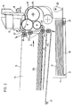
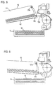
- the embodiment of the printer illustrated in figures 1 and 2 comprises a frame 10, a first receptacle 11 for the sheets to be printed 12, a printing zone 14 and a second receptacle 15 provided for receiving the sheets after they have been printed completely.
- a printhead 17 is borne by a carriage 16 mounted slidingly on at least one transversal bar 18 and adapted so as to print a sheet 12a following a backward and forward movement.
- the first receptacle 11 possesses a movable support plate 20 hinge-mounted on the walls of the receptacle according to a pivoting axis 21 and urged by a spring 22 against a command cam 23.
- a command cam 23 When the latter is in the position illustrated, the stack of sheets 12 is in a position withdrawn from the selection rollers 26.
- the uppermost sheet of the stack 12 is urged against the selection rollers 26 which, by way of a rotation in the anti-clockwise direction, are suitable for feeding the sheet towards the printing zone 14, following a feeding path 27.
- the latter is bounded by guiding elements 28, 29, 30 and effects a reversal 34 of the sheet about a main roller 31, so that the latter is reversed as it is fed about an axis 32 which is perpendicular to the conveying direction 33 of the sheets.
- Auxiliary guiding rollers 36, 37, 38 are moreover arranged along this sheet feeding path forming a printing exit 39.
- the printer comprises an installation 40 for the duplex printing of the sheets.
- the latter possesses an intermediate storing device 41 comprising, in this embodiment, two storage trays 42, 43 arranged under the second receptacle 15 and forming with the latter a rigid group 44 mounted pivotingly on the frame 10 according to a pivoting axis 45 which is perpendicular to the conveying direction 33 of the sheets.
- a control mechanism 50 permits this group 44 to effect the pivoting movement and comprises a rack 51 forming a partial arc of a circle meshing with a double pinion 52 driven by a step motor 53 controlled by a control unit 54 of the printer.
- Each storage tray 42, 43 comprises a conveying member 57 fitted at its entrance.
- this conveying member 57 is comprised by toothed wheels 58 integral with a transversal shaft and cooperating with backing rollers 59.
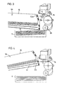
- the second receptacle 15 provided for the printed sheets 12b is equipped, substantially at its entrance facing the printhead 17, with a number of superposed conveying members 57 equal in number to that of the superposed storage trays 42, 43, that is to say, in this embodiment, two.
- conveying members of the storage trays, and those of the second receptacle 15, are arranged in identical fashion one on top of the other so that they can be put in meshing engagement simultaneously, two by two, with driving members 60 mounted superposed on the frame 10 at a predetermined distance from each other.
- the shafts of the toothed wheels 58 are integral at their extremity, with pinions 61 suitable for meshing with two driving pinions 62, 63 in meshing engagement with a sheet transport gear train 64.
- the group 44 consisting of the receptacle 15 and the storage trays 42, 43 can be pivoted about the axis 45 in order to activate both the toothed wheels 58 of the lower storage tray 43 and the lower toothed wheels of the second receptacle 15, and also the toothed wheels of the upper storage tray 42 and the upper toothed wheels of the second receptacle 15, in accordance with command signals provided by the control unit 54.
- the conveying members 57 of the storage trays are provided for gripping and feeding a printed sheet into the storage tray 42, 43, for retaining it with its printed face facing upwards during the intermediate storage, enabling the ink to dry fully, and for feeding it again through a printing entrance 65 into the feeding path 27 for the printing of its second face.
- the storage trays 42, 43 are high enough so that the upper printed surface of the sheets does not touch the walls of the tray, the ink can thus dry without forming blotches.
- the printing entrance 65 of the sheets coming from the storage trays is different from that 66 for the new sheets selected from the first receptacle 11.
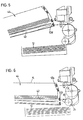
- the succession of events of a printing cycle is illustrated in figures 3 to 7.
- the position illustrated in figure 3 corresponds to the stand-by position between two printing cycles. It also corresponds to the position for front face printing, wherein a sheet is selected by the rollers 26 and conveyed to the printing zone 14.
- the group 44 which together with the control mechanism 50 forms a directing means, is in the lowest position in which the highest conveying member 57a is arranged facing the printing zone.
- the printed sheet 12a is gripped by this conveying member 57a which places it in the second receptacle 15.
- the fact that the highest conveying member 57a is used means that an optimal thickness of sheets can be placed in the second receptacle 15.
- the uppermost sheet of the stack 12 is fed and printed.
- the group 44 is then turned and raised so that the conveying member 57c is facing the printing zone 14 (fig. 4).
- the sheet printed on its upper face is fed into the upper storage tray 42. It should be pointed out that the toothed wheels of the conveying member retain this sheet while it is being dried and that this sheet does not touch the walls of the tray.
- the following sheet is then selected, printed and fed by the conveying member 57d into the lower storage tray 43, after the group 44 has been raised by a predetermined angular distance (fig. 5).
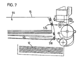
- this group 44 is then lowered so that the conveying member 57c and the upper storage tray 42 are facing the printing entrance 65.
- the stack of sheets 12 is lowered and removed from the rollers 26.
- the first sheet is extracted by the conveying member 57c from the upper storage tray 42 and fed through the printing entrance 65 towards the printing zone while undergoing a reversal about the main roller 31 so that the already printed face is now facing downwards.
- the sheet can thus be printed on its back face, gripped by the conveying member 57a and placed in the second receptacle 15.
- the group 44 is then turned and raised so that the conveying member 57d and the lower storage tray 43 are facing the printing entrance 65 (fig. 7).
- the sheet stored temporarily in this tray is then fed by the conveying member 57d, printed on its back face, gripped by the conveying member 57b and placed in the second receptacle 15.
- a new printing cycle can then commence, or the group can be lowered into the stand-by position illustrated in figure 3.
- the intermediate storing device 41 permits a drying of the ink following printing.
- the printed surface does not rub against the walls of a guiding channel, as is the case in the known printers.
- the invention is therefore particularly well suited to ink jet printers for which duplex printing installations were not previously suitable. In order to optimise the performance of the printer, some movements may be made simultaneous, provided that the drying time of the ink is respected.
- the variant illustrated in figures 8 and 9 differs from the embodiment described above in that it comprises only one intermediate storage tray 42 equipped with one conveying member 57c.
- the second receptacle 15 possesses only one conveying member 57a.
- a sheet 12a is selected, printed and fed into the intermediate storage tray 42, when the group 44 is raised (fig. 8). This group 44 is then lowered and when the ink is dry, the sheet is taken out, printed on the back face, taken again by the conveying member 57a and placed in the receptacle 15 (fig. 9).
- This simplified variant ensures a reliable duplex printing with uncomplicated equipment and low overall dimensions.
- first and second receptacles could be arranged differently, for example they could be disposed at either side of the printing zone.
- the intermediate storage trays could be of a different number, for example 10 in a larger size printer. They could also be separate from the second tray 15 and form a distinct, temporary storage unit.
- the group 44 could also be displaced by lateral translation.
- the conveying members 57 could be of a type other than with toothed wheels, for example rollers co-operating with the lateral margins of the sheets.
- the feeding path 27 could be disposed differently, but must nonetheless ensure the reversal of the sheet for duplex printing.
- the invention is particularly well suited to ink jet printers, but may also be advantageously applied on other types of printers.
Landscapes
- Sheets, Magazines, And Separation Thereof (AREA)
- Ink Jet (AREA)
- Handling Of Cut Paper (AREA)
- Pile Receivers (AREA)
Abstract
Description
- This invention relates to a printer comprising a frame, at least one first receptacle for the sheets to be printed, a sheet feeding path with a printing zone and at least one second receptacle for receiving the printed sheets.
- Duplex printing within the framework of printers using an ink that needs a certain length of time to dry, such as ink jet printers, is delicate on account of the fact that the ink of a sheet printed on its front face can easily come into contact with members of the printer, such as the guiding walls, during the reversal of the sheet, giving rise to undesirable ink erasures and blotches.
- A large size printer is known from US Patent no. 4,918,490 in which the sheets slide, between the printing of the first and of the second face, in a long guiding channel the length of which is approximately three sheets. In this channel, the printed face touches the walls of the channel. For this reason, the arrangement described in this American patent cannot be used as part of ink printers having a more or less lengthy drying time, such as ink jet printers. Moreover, the printer described in this American patent is complex to build and has large overall dimensions, making it impossible to use for many applications.
- The object of this invention is to overcome the drawbacks cited above and to create a printer permitting reliable duplex printing, including with inks having a relatively long drying time, such as ink jet printers. This printer shall in addition have to be easy to build and low reduced overall dimensions, while ensuring high quality printing. The cost price of the printer, moreover, shall have to be as low as possible.
- The printer according to the invention is accordingly characterized by the fact that it comprises an installation for the duplex printing of sheets with an intermediate storing device having at least one storage tray, this installation being equipped with a control mechanism suitable for displacing the intermediate storing device so that the sheet or sheets printed on a first face can, successive to a printing exit, be fed into the storage tray or trays, in which a sheet is retained with its printed face facing upwards and from which the sheet or sheets may be fed again, for the printing of their second face, through a printing entrance into the feeding path, the latter being arranged in such a way that the sheet or sheets effect a reversal between the printing entrance and exit.
- Accordingly, the ink still wet from printing can dry during a predetermined period of time when the sheet is kept in the intermediate storage tray. This storage tray is also used as a conveying means for presenting the sheet at the printing entrance again so that printing can be effected on its second face. This disposition therefore permits, reliably and simply, the effecting of duplex printing within the framework of ink jet printers or other types of printers with drying inks. The invention also permits a reduction of the overall dimensions of duplex printers and it is simple to build, using a small number of parts, at a reasonable cost price. The quality and speed of handling of the sheets are also very high.
- To advantage, each storage tray comprises substantially at its entrance a conveying device provided for gripping and feeding a printed sheet into the storage tray, for keeping it during the intermediate storage and for feeding it again through the printing entrance into the said feeding path for the printing of its second face.
- These characteristics ensure an optimal intermediate storage and drying, while facilitating the handling of the sheets.
- According to a preferred embodiment, the second receptacle and the storage tray or trays together form an integral whole, mounted movably on the frame.
- A particularly simple construction and very low overall dimensions are accordingly obtained.
- Advantageously, the second receptacle is provided, substantially at its entrance, with a number of superposed conveying members identical in number to that of the superposed storage trays, the conveying members of the storage trays and those of the second receptacle being arranged identically, one on top of the other, so that the corresponding conveying members of one of the storage trays and of the second receptacle are suitable for meshing simultaneously with two driving members superposed on the frame and separated from each other by a predetermined distance.
- The driving of the sheet conveying members is accordingly performed in a particularly rational and reliable manner and with very few components.
- Other advantages will become apparent from the characteristics set down in the relevant claims and from the description provided below detailing the invention, with the aid of drawings representing schematically and by way of example one embodiment and variants thereof.
- Figure 1 is a section view of one embodiment of the printer,
- Figure 2 is a lateral view of this embodiment.
- Figures 3 to 7 illustrate a sectional view of the printer in different working positions.
- Figures 8 and 9 illustrate a sectional view of a variant in two working positions.
-
- The embodiment of the printer illustrated in figures 1 and 2 comprises a
frame 10, afirst receptacle 11 for the sheets to be printed 12, aprinting zone 14 and asecond receptacle 15 provided for receiving the sheets after they have been printed completely. - In the
printing zone 14, aprinthead 17 is borne by acarriage 16 mounted slidingly on at least onetransversal bar 18 and adapted so as to print asheet 12a following a backward and forward movement. - The
first receptacle 11 possesses amovable support plate 20 hinge-mounted on the walls of the receptacle according to apivoting axis 21 and urged by aspring 22 against acommand cam 23. When the latter is in the position illustrated, the stack ofsheets 12 is in a position withdrawn from theselection rollers 26. Conversely, following rotation of thiscam 23 through an angle of 90°, the uppermost sheet of thestack 12 is urged against theselection rollers 26 which, by way of a rotation in the anti-clockwise direction, are suitable for feeding the sheet towards theprinting zone 14, following a feeding path 27. The latter is bounded by guidingelements reversal 34 of the sheet about amain roller 31, so that the latter is reversed as it is fed about anaxis 32 which is perpendicular to the conveyingdirection 33 of the sheets. Auxiliary guidingrollers printing exit 39. - The printer comprises an installation 40 for the duplex printing of the sheets. The latter possesses an
intermediate storing device 41 comprising, in this embodiment, twostorage trays second receptacle 15 and forming with the latter arigid group 44 mounted pivotingly on theframe 10 according to apivoting axis 45 which is perpendicular to the conveyingdirection 33 of the sheets. - A
control mechanism 50 permits thisgroup 44 to effect the pivoting movement and comprises arack 51 forming a partial arc of a circle meshing with a double pinion 52 driven by astep motor 53 controlled by acontrol unit 54 of the printer. - Each
storage tray member 57 fitted at its entrance. To advantage, this conveyingmember 57 is comprised by toothed wheels 58 integral with a transversal shaft and cooperating withbacking rollers 59. - The
second receptacle 15 provided for the printedsheets 12b is equipped, substantially at its entrance facing theprinthead 17, with a number of superposed conveyingmembers 57 equal in number to that of thesuperposed storage trays - These conveying members of the storage trays, and those of the
second receptacle 15, are arranged in identical fashion one on top of the other so that they can be put in meshing engagement simultaneously, two by two, with drivingmembers 60 mounted superposed on theframe 10 at a predetermined distance from each other. - As is shown in figure 2, the shafts of the toothed wheels 58 are integral at their extremity, with
pinions 61 suitable for meshing with twodriving pinions transport gear train 64. Accordingly, thegroup 44 consisting of thereceptacle 15 and thestorage trays axis 45 in order to activate both the toothed wheels 58 of thelower storage tray 43 and the lower toothed wheels of thesecond receptacle 15, and also the toothed wheels of theupper storage tray 42 and the upper toothed wheels of thesecond receptacle 15, in accordance with command signals provided by thecontrol unit 54. - It should be noted that the conveying
members 57 of the storage trays are provided for gripping and feeding a printed sheet into thestorage tray printing entrance 65 into the feeding path 27 for the printing of its second face. - The storage trays 42, 43 are high enough so that the upper printed surface of the sheets does not touch the walls of the tray, the ink can thus dry without forming blotches. The
printing entrance 65 of the sheets coming from the storage trays is different from that 66 for the new sheets selected from thefirst receptacle 11. - The succession of events of a printing cycle is illustrated in figures 3 to 7. The position illustrated in figure 3 corresponds to the stand-by position between two printing cycles. It also corresponds to the position for front face printing, wherein a sheet is selected by the
rollers 26 and conveyed to theprinting zone 14. Thegroup 44, which together with thecontrol mechanism 50 forms a directing means, is in the lowest position in which the highest conveyingmember 57a is arranged facing the printing zone. The printedsheet 12a is gripped by this conveyingmember 57a which places it in thesecond receptacle 15. The fact that the highest conveyingmember 57a is used means that an optimal thickness of sheets can be placed in thesecond receptacle 15. - When a duplex printing is commanded, the uppermost sheet of the
stack 12 is fed and printed. Thegroup 44 is then turned and raised so that the conveyingmember 57c is facing the printing zone 14 (fig. 4). The sheet printed on its upper face is fed into theupper storage tray 42. It should be pointed out that the toothed wheels of the conveying member retain this sheet while it is being dried and that this sheet does not touch the walls of the tray. - The following sheet is then selected, printed and fed by the conveying
member 57d into thelower storage tray 43, after thegroup 44 has been raised by a predetermined angular distance (fig. 5). - With reference to figure 6, this
group 44 is then lowered so that the conveyingmember 57c and theupper storage tray 42 are facing theprinting entrance 65. The stack ofsheets 12 is lowered and removed from therollers 26. - The first sheet, the ink of which is now dry, is extracted by the conveying
member 57c from theupper storage tray 42 and fed through theprinting entrance 65 towards the printing zone while undergoing a reversal about themain roller 31 so that the already printed face is now facing downwards. The sheet can thus be printed on its back face, gripped by the conveyingmember 57a and placed in thesecond receptacle 15. - The
group 44 is then turned and raised so that the conveyingmember 57d and thelower storage tray 43 are facing the printing entrance 65 (fig. 7). The sheet stored temporarily in this tray is then fed by the conveyingmember 57d, printed on its back face, gripped by the conveyingmember 57b and placed in thesecond receptacle 15. - A new printing cycle can then commence, or the group can be lowered into the stand-by position illustrated in figure 3.
- Accordingly, the
intermediate storing device 41 permits a drying of the ink following printing. The printed surface does not rub against the walls of a guiding channel, as is the case in the known printers. The invention is therefore particularly well suited to ink jet printers for which duplex printing installations were not previously suitable. In order to optimise the performance of the printer, some movements may be made simultaneous, provided that the drying time of the ink is respected. - The variant illustrated in figures 8 and 9 differs from the embodiment described above in that it comprises only one
intermediate storage tray 42 equipped with one conveyingmember 57c. Thesecond receptacle 15 possesses only one conveyingmember 57a. Asheet 12a is selected, printed and fed into theintermediate storage tray 42, when thegroup 44 is raised (fig. 8). Thisgroup 44 is then lowered and when the ink is dry, the sheet is taken out, printed on the back face, taken again by the conveyingmember 57a and placed in the receptacle 15 (fig. 9). This simplified variant ensures a reliable duplex printing with uncomplicated equipment and low overall dimensions. - Nevertheless, it implies a sequential treatment of the sheets and of the pages.
- Naturally the embodiment and variant thereof described above do not have any restricting characteristics and all the modifications desired may be made thereto within the scope as defined in
claim 1. In particular, the first and second receptacles could be arranged differently, for example they could be disposed at either side of the printing zone. The intermediate storage trays could be of a different number, for example 10 in a larger size printer. They could also be separate from thesecond tray 15 and form a distinct, temporary storage unit. Instead of a pivoting movement, thegroup 44 could also be displaced by lateral translation. The conveyingmembers 57 could be of a type other than with toothed wheels, for example rollers co-operating with the lateral margins of the sheets. - The feeding path 27 could be disposed differently, but must nonetheless ensure the reversal of the sheet for duplex printing. The invention is particularly well suited to ink jet printers, but may also be advantageously applied on other types of printers.
Claims (9)
- Printer comprising a frame (10), at least one first receptacle (11) for the sheets to be printed (12), a sheet feeding path (27) with a printing zone (14), and at least one second receptacle (15) for receiving the printed sheets, characterized by the fact that said printer comprises an installation (40) for the duplex printing of the sheets having an intermediate storing device (41) possessing at least one storage tray (42, 43), said installation being equipped with a control mechanism (50) suitable for displacing the intermediate storing device (41) so that the sheet or sheets printed on a first face can, successively to a printing exit, be fed into the storage tray(s) (42, 43), in which a sheet is retained with its printed face facing upwards and from which the sheet or sheets can be fed again, for the printing of their second face, through a printing entrance (65) into the feeding path (27), the latter being arranged in such a way that the sheet or sheets effect a reversal (34) between the printing entrance and exit (65,39).
- Printer according to claim 1, characterized by the fact that the feeding path (27) is arranged in such a way that the sheet effects a reversal (34) about an axis (32) perpendicular to the sheet conveying direction (33).
- Printer according to claim 1 or 2, characterized by the fact that each storage tray (42, 43) comprises substantially at its entrance a conveying member (57) provided for gripping and feeding a printed sheet into the storage tray, for keeping it during the intermediate storage and for feeding it again through the printing entrance (65) into said feeding path (27) for the printing of its second face.
- Printer according to any of the preceding claims, characterized by the fact that the intermediate storing device (41) with the storage tray(s) (42, 43) is arranged movably under the second receptacle (15).
- Printer according to claim 4, characterized by the fact that the second receptacle (15) and the storage tray(s) (42, 43) form an integral group (44) fitted movably on the frame (10).
- Printer according to claim 4 or 5, characterized by the fact that the first receptacle (11) is arranged at east partially under the intermediate storing device (41).
- Printer according to claim 5 or 6, characterized by the fact that said integral group (44) is pivotingly mounted on the frame (10) according to a pivoting axis (45) perpendicular to the direction of displacement (33) of the sheets.
- Printer according to the claims 3 and 5, characterized by the fact that the second receptacle (15) is provided, substantially at its entrance, with a number of superposed conveying members (57) identical in number to that of the superposed storage trays (42, 43), the conveying members (57c, 57d) of the storage trays (42, 43) and those (57a, 57b) of the second receptacle (15) being arranged in identical fashion one above the other so that the corresponding conveying members (57a, 57c; 57b, 57d) of one of the storage trays (42, 43) and of the second receptacle (15) are suitable for being in meshing engagement simultaneously with two driving members (61) superposed on the frame (10) and separated from each other by a predetermined distance.
- Printer according to claim 3 or 8, characterized by the fact that the conveying members (57) are comprised by toothed wheels (58) co-operating with backing rollers (59).
Applications Claiming Priority (2)
| Application Number | Priority Date | Filing Date | Title |
|---|---|---|---|
| CH00928/98A CH692575A5 (en) | 1998-04-23 | 1998-04-23 | Printer front -verso. |
| CH0092898 | 1998-04-23 |
Publications (3)
| Publication Number | Publication Date |
|---|---|
| EP0952002A2 true EP0952002A2 (en) | 1999-10-27 |
| EP0952002A3 EP0952002A3 (en) | 2001-03-21 |
| EP0952002B1 EP0952002B1 (en) | 2003-03-19 |
Family
ID=4198438
Family Applications (1)
| Application Number | Title | Priority Date | Filing Date |
|---|---|---|---|
| EP99107631A Expired - Lifetime EP0952002B1 (en) | 1998-04-23 | 1999-04-16 | Duplex-printer |
Country Status (4)
| Country | Link |
|---|---|
| US (1) | US6250754B1 (en) |
| EP (1) | EP0952002B1 (en) |
| CH (1) | CH692575A5 (en) |
| DE (1) | DE69905961T2 (en) |
Cited By (1)
| Publication number | Priority date | Publication date | Assignee | Title |
|---|---|---|---|---|
| EP2275271A1 (en) * | 2009-07-16 | 2011-01-19 | Fujifilm Corporation | Printed matter seasoning apparatus and method, and inkjet recording apparatus |
Families Citing this family (12)
| Publication number | Priority date | Publication date | Assignee | Title |
|---|---|---|---|---|
| US6612240B1 (en) * | 2000-09-15 | 2003-09-02 | Silverbrook Research Pty Ltd | Drying of an image on print media in a modular commercial printer |
| US6669190B1 (en) * | 2002-07-12 | 2003-12-30 | Lite-On Technology Corporation | Double-side automatic feeding apparatus |
| JP2004195956A (en) * | 2002-10-22 | 2004-07-15 | Ricoh Co Ltd | Ink jet recording device, copier and recording medium |
| US7201524B2 (en) * | 2005-01-28 | 2007-04-10 | Xerox Corporation | Media path direction control device and method of reversing a media path |
| JP4492380B2 (en) * | 2005-02-04 | 2010-06-30 | 富士ゼロックス株式会社 | Recording device |
| JP2006256158A (en) * | 2005-03-17 | 2006-09-28 | Fuji Xerox Co Ltd | Image recording device |
| JP4687287B2 (en) * | 2005-07-05 | 2011-05-25 | 富士ゼロックス株式会社 | Droplet discharge device |
| US7731184B2 (en) * | 2005-07-15 | 2010-06-08 | Hewlett-Packard Development Company, L.P. | Duplexer |
| US20070132796A1 (en) * | 2005-12-09 | 2007-06-14 | Anne Jovanovic | Print again assembly |
| JP4921796B2 (en) * | 2006-01-11 | 2012-04-25 | セイコーインスツル株式会社 | Printer and recording method |
| JP2008184323A (en) * | 2007-01-31 | 2008-08-14 | Brother Ind Ltd | Sheet sorting apparatus and image recording apparatus having the same |
| JP5130853B2 (en) | 2007-09-28 | 2013-01-30 | ブラザー工業株式会社 | Image recording device |
Citations (1)
| Publication number | Priority date | Publication date | Assignee | Title |
|---|---|---|---|---|
| US4918490A (en) | 1989-07-19 | 1990-04-17 | Xerox Corporation | Batch mode duplex printing |
Family Cites Families (5)
| Publication number | Priority date | Publication date | Assignee | Title |
|---|---|---|---|---|
| US4453841A (en) * | 1982-03-08 | 1984-06-12 | The Mead Corporation | Duplex printing system and method therefor |
| DE3632517A1 (en) * | 1986-09-22 | 1988-03-24 | Siemens Ag | DEVICE FOR RECORDING IMAGE INFORMATION ON EACH SIDE OF RECORDING SHEETS |
| DE3810223C2 (en) * | 1987-04-02 | 1994-05-26 | Minolta Camera Kk | Duplex printing system |
| JP3245302B2 (en) * | 1993-07-22 | 2002-01-15 | キヤノン株式会社 | Sheet member conveying device and information processing device using the same |
| US5991564A (en) * | 1998-10-02 | 1999-11-23 | Tektronix, Inc. | Electrophotographic duplex printing media system |
-
1998
- 1998-04-23 CH CH00928/98A patent/CH692575A5/en not_active IP Right Cessation
-
1999
- 1999-04-16 EP EP99107631A patent/EP0952002B1/en not_active Expired - Lifetime
- 1999-04-16 DE DE69905961T patent/DE69905961T2/en not_active Expired - Lifetime
- 1999-04-21 US US09/295,383 patent/US6250754B1/en not_active Expired - Lifetime
Patent Citations (1)
| Publication number | Priority date | Publication date | Assignee | Title |
|---|---|---|---|---|
| US4918490A (en) | 1989-07-19 | 1990-04-17 | Xerox Corporation | Batch mode duplex printing |
Cited By (2)
| Publication number | Priority date | Publication date | Assignee | Title |
|---|---|---|---|---|
| EP2275271A1 (en) * | 2009-07-16 | 2011-01-19 | Fujifilm Corporation | Printed matter seasoning apparatus and method, and inkjet recording apparatus |
| CN101955075A (en) * | 2009-07-16 | 2011-01-26 | 富士胶片株式会社 | Printed matter seasoning apparatus and method, and inkjet recording apparatus |
Also Published As
| Publication number | Publication date |
|---|---|
| DE69905961D1 (en) | 2003-04-24 |
| CH692575A5 (en) | 2002-08-15 |
| EP0952002A3 (en) | 2001-03-21 |
| EP0952002B1 (en) | 2003-03-19 |
| US6250754B1 (en) | 2001-06-26 |
| DE69905961T2 (en) | 2003-12-04 |
Similar Documents
| Publication | Publication Date | Title |
|---|---|---|
| CA1295181C (en) | Single sheet ink-jet printer with passive drying system | |
| US6250754B1 (en) | Duplex printer | |
| DE69809353T2 (en) | Sheet feeder with a compact transport path | |
| JP5400175B2 (en) | Inkjet printer and media feeding method | |
| JPH115664A (en) | Paper ejection stack device and image forming apparatus provided with the same | |
| US4565462A (en) | Paper loading apparatus for printer including plural feed paths | |
| US5378071A (en) | Video printer | |
| JP3935310B2 (en) | Internal paper guide for printer media shape control | |
| US20060091599A1 (en) | Feeder provided with edge guide member | |
| US5328280A (en) | Printer having means for switching medium feed path from sheet feed path to web feed path or vice versa | |
| DE69020945T2 (en) | Recording device. | |
| US4522519A (en) | Apparatus and process for drop-feeding sheets to a typing or printing machine including separable paper clamping trays | |
| DE69128672T2 (en) | Sheet feeder | |
| JP2020026069A (en) | Maintenance device and liquid discharge device | |
| JP3537326B2 (en) | Image forming device | |
| JP3092040U (en) | Duplex printer for paper processing | |
| US7080948B2 (en) | Paper ejecting mechanism and ink-jet printer having the paper ejecting mechanism | |
| DE60008333T2 (en) | Recording media handling system | |
| JP3765785B2 (en) | Ink jet printer drive roller release device | |
| US5139355A (en) | Printer with multi-tractor form shuttle | |
| JP4877301B2 (en) | Image recording apparatus and recording paper conveyance control method | |
| JP2580022B2 (en) | Automatic paper feeder | |
| JPH0880650A (en) | Paper feeding device of printer | |
| JP3687605B2 (en) | Page change device | |
| JPS61291372A (en) | Automatic sheet feeder for printer |
Legal Events
| Date | Code | Title | Description |
|---|---|---|---|
| PUAI | Public reference made under article 153(3) epc to a published international application that has entered the european phase |
Free format text: ORIGINAL CODE: 0009012 |
|
| AK | Designated contracting states |
Kind code of ref document: A2 Designated state(s): DE FR GB IT |
|
| AX | Request for extension of the european patent |
Free format text: AL;LT;LV;MK;RO;SI |
|
| PUAL | Search report despatched |
Free format text: ORIGINAL CODE: 0009013 |
|
| AK | Designated contracting states |
Kind code of ref document: A3 Designated state(s): AT BE CH CY DE DK ES FI FR GB GR IE IT LI LU MC NL PT SE |
|
| AX | Request for extension of the european patent |
Free format text: AL;LT;LV;MK;RO;SI |
|
| RIC1 | Information provided on ipc code assigned before grant |
Free format text: 7B 41J 13/00 A, 7B 41J 3/60 B |
|
| RAP1 | Party data changed (applicant data changed or rights of an application transferred) |
Owner name: OLIVETTI TECNOST S.P.A. |
|
| 17P | Request for examination filed |
Effective date: 20010912 |
|
| AKX | Designation fees paid |
Free format text: DE FR GB IT |
|
| 17Q | First examination report despatched |
Effective date: 20020115 |
|
| GRAH | Despatch of communication of intention to grant a patent |
Free format text: ORIGINAL CODE: EPIDOS IGRA |
|
| GRAH | Despatch of communication of intention to grant a patent |
Free format text: ORIGINAL CODE: EPIDOS IGRA |
|
| GRAA | (expected) grant |
Free format text: ORIGINAL CODE: 0009210 |
|
| AK | Designated contracting states |
Designated state(s): DE FR GB IT |
|
| REG | Reference to a national code |
Ref country code: GB Ref legal event code: FG4D |
|
| REF | Corresponds to: |
Ref document number: 69905961 Country of ref document: DE Date of ref document: 20030424 Kind code of ref document: P |
|
| ET | Fr: translation filed | ||
| PLBE | No opposition filed within time limit |
Free format text: ORIGINAL CODE: 0009261 |
|
| STAA | Information on the status of an ep patent application or granted ep patent |
Free format text: STATUS: NO OPPOSITION FILED WITHIN TIME LIMIT |
|
| 26N | No opposition filed |
Effective date: 20031222 |
|
| REG | Reference to a national code |
Ref country code: FR Ref legal event code: ST Effective date: 20081231 |
|
| PG25 | Lapsed in a contracting state [announced via postgrant information from national office to epo] |
Ref country code: FR Free format text: LAPSE BECAUSE OF NON-PAYMENT OF DUE FEES Effective date: 20080430 |
|
| REG | Reference to a national code |
Ref country code: FR Ref legal event code: D3 |
|
| REG | Reference to a national code |
Ref country code: FR Ref legal event code: PLFP Year of fee payment: 17 |
|
| REG | Reference to a national code |
Ref country code: DE Ref legal event code: R082 Ref document number: 69905961 Country of ref document: DE Representative=s name: WEICKMANN & WEICKMANN PATENTANWAELTE - RECHTSA, DE Ref country code: DE Ref legal event code: R082 Ref document number: 69905961 Country of ref document: DE Representative=s name: PATENTANWAELTE WEICKMANN & WEICKMANN, DE |
|
| PGFP | Annual fee paid to national office [announced via postgrant information from national office to epo] |
Ref country code: DE Payment date: 20150429 Year of fee payment: 17 Ref country code: GB Payment date: 20150427 Year of fee payment: 17 |
|
| PGFP | Annual fee paid to national office [announced via postgrant information from national office to epo] |
Ref country code: FR Payment date: 20150417 Year of fee payment: 17 Ref country code: IT Payment date: 20150429 Year of fee payment: 17 |
|
| REG | Reference to a national code |
Ref country code: DE Ref legal event code: R119 Ref document number: 69905961 Country of ref document: DE |
|
| GBPC | Gb: european patent ceased through non-payment of renewal fee |
Effective date: 20160416 |
|
| REG | Reference to a national code |
Ref country code: FR Ref legal event code: ST Effective date: 20161230 |
|
| PG25 | Lapsed in a contracting state [announced via postgrant information from national office to epo] |
Ref country code: DE Free format text: LAPSE BECAUSE OF NON-PAYMENT OF DUE FEES Effective date: 20161101 Ref country code: FR Free format text: LAPSE BECAUSE OF NON-PAYMENT OF DUE FEES Effective date: 20160502 Ref country code: GB Free format text: LAPSE BECAUSE OF NON-PAYMENT OF DUE FEES Effective date: 20160416 |
|
| PG25 | Lapsed in a contracting state [announced via postgrant information from national office to epo] |
Ref country code: IT Free format text: LAPSE BECAUSE OF NON-PAYMENT OF DUE FEES Effective date: 20160416 |