EP0951636B1 - Navigationssystem mit einer wegeerfassungsvorrichtung - Google Patents
Navigationssystem mit einer wegeerfassungsvorrichtung Download PDFInfo
- Publication number
- EP0951636B1 EP0951636B1 EP98949176A EP98949176A EP0951636B1 EP 0951636 B1 EP0951636 B1 EP 0951636B1 EP 98949176 A EP98949176 A EP 98949176A EP 98949176 A EP98949176 A EP 98949176A EP 0951636 B1 EP0951636 B1 EP 0951636B1
- Authority
- EP
- European Patent Office
- Prior art keywords
- state
- signal
- input
- output
- sensor
- Prior art date
- Legal status (The legal status is an assumption and is not a legal conclusion. Google has not performed a legal analysis and makes no representation as to the accuracy of the status listed.)
- Expired - Lifetime
Links
- 230000006870 function Effects 0.000 claims description 2
- 238000001514 detection method Methods 0.000 description 18
- 239000003990 capacitor Substances 0.000 description 17
- 238000010586 diagram Methods 0.000 description 10
- 230000001419 dependent effect Effects 0.000 description 6
- 238000011156 evaluation Methods 0.000 description 3
- 230000006698 induction Effects 0.000 description 3
- 230000002093 peripheral effect Effects 0.000 description 2
- 230000001681 protective effect Effects 0.000 description 2
- 230000000630 rising effect Effects 0.000 description 2
- 230000000007 visual effect Effects 0.000 description 2
- XEEYBQQBJWHFJM-UHFFFAOYSA-N Iron Chemical group [Fe] XEEYBQQBJWHFJM-UHFFFAOYSA-N 0.000 description 1
- 238000003708 edge detection Methods 0.000 description 1
- VKYKSIONXSXAKP-UHFFFAOYSA-N hexamethylenetetramine Chemical compound C1N(C2)CN3CN1CN2C3 VKYKSIONXSXAKP-UHFFFAOYSA-N 0.000 description 1
- 238000005259 measurement Methods 0.000 description 1
- 238000010295 mobile communication Methods 0.000 description 1
Images

Classifications
-
- G—PHYSICS
- G01—MEASURING; TESTING
- G01P—MEASURING LINEAR OR ANGULAR SPEED, ACCELERATION, DECELERATION, OR SHOCK; INDICATING PRESENCE, ABSENCE, OR DIRECTION, OF MOVEMENT
- G01P21/00—Testing or calibrating of apparatus or devices covered by the preceding groups
- G01P21/02—Testing or calibrating of apparatus or devices covered by the preceding groups of speedometers
-
- G—PHYSICS
- G01—MEASURING; TESTING
- G01C—MEASURING DISTANCES, LEVELS OR BEARINGS; SURVEYING; NAVIGATION; GYROSCOPIC INSTRUMENTS; PHOTOGRAMMETRY OR VIDEOGRAMMETRY
- G01C21/00—Navigation; Navigational instruments not provided for in groups G01C1/00 - G01C19/00
- G01C21/26—Navigation; Navigational instruments not provided for in groups G01C1/00 - G01C19/00 specially adapted for navigation in a road network
- G01C21/28—Navigation; Navigational instruments not provided for in groups G01C1/00 - G01C19/00 specially adapted for navigation in a road network with correlation of data from several navigational instruments
-
- G—PHYSICS
- G01—MEASURING; TESTING
- G01D—MEASURING NOT SPECIALLY ADAPTED FOR A SPECIFIC VARIABLE; ARRANGEMENTS FOR MEASURING TWO OR MORE VARIABLES NOT COVERED IN A SINGLE OTHER SUBCLASS; TARIFF METERING APPARATUS; MEASURING OR TESTING NOT OTHERWISE PROVIDED FOR
- G01D18/00—Testing or calibrating apparatus or arrangements provided for in groups G01D1/00 - G01D15/00
- G01D18/002—Automatic recalibration
- G01D18/004—Continuous recalibration
Definitions
- the invention relates to a path detection device or a navigation system with a path detection device, the at least one sensor for supplying a sinus or rectangular signal and a converter circuit for Delivery of a rectangular signal as a measure of the distance traveled Contains path of the vehicle.
- a path detection device contains at least one active or one passive Sensor that signals depending on the distance traveled Way delivers.
- a passive sensor delivers a sinusoidal one Signal, which for example has an amplitude of 1 mV to 50 V.
- An active sensor delivers a rectangular signal with a type-dependent amplitude between 5 V and 12 V. This rectangular signal can with interference with an amplitude be affected by 1 V, for example by the Alternator.
- a circuit arrangement is known from DE-A-196 02 243, which enables an active sensor with an electronic Link evaluation for a passive sensor has been designed.
- the evaluation circuit contains a comparator, the output signal of a further evaluation is fed, which is a speed-proportional signal supplies.
- the invention has for its object a path detection device or a navigation system with such To create path detection device, the sinus or rectangular, supplied by at least one sensor Signals largely undisturbed rectangular signals forms.
- the detector is switched on after the navigation system is switched on and when you start driving or after switching the navigation system off and on again determined while driving whether one or more sensors are sine or rectangular signals are supplied.
- the detection can only be up to a medium one Speed of e.g. 100 km / h can be carried out.
- a first state is saved when a sinusoidal Signal has been detected. Otherwise, a second state is saved.
- the sinusoidal signal is passed through an amplifier circuit and then in one Comparator circuit converted into a rectangular signal. In the second state it will rectangular signal not via the amplifier circuit, but directly the Comparator circuit supplied.
- the rectangular signal is therefore not amplified.
- an alternator e.g. with an amplitude of 1 V
- the sinusoidal or rectangular signal derived from at least one sensor becomes passed via a changeover switch to the amplifier or comparator circuit, as in claim 2 executed.
- An embodiment of the detector is in claim 3, the latch in Claim 4 and the comparator circuit described in claim 5.
- the invention relates also on a path detection device as described in claim 6. Furthermore, the path detection device according to the invention for controlling a speed display device or other devices for evaluating speed-dependent Signals are used.
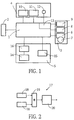
- Fig. 1 is an embodiment of a navigation system for land vehicles as Block diagram shown.
- the navigation system contains a control arrangement 1, a Measuring arrangement 2, a data source arrangement 3, an input arrangement 4 and a Output arrangement 5.
- the control arrangement 1 can for example be a microprocessor included, which among other things performs the navigation calculations and with at least one Read-only memory (ROM) e.g. to execute a program and a write and Read-only memory (RAM) is coupled for storing data during operation.
- ROM Read-only memory
- RAM write and Read-only memory
- GPS Global Positioning System
- the GPS receiving unit delivers based on received satellite data also the current position of the vehicle and gives the calculated position data to the control arrangement 1.
- the data source arrangement 3 contains at least one device for delivery digitally coded geographic data from a data memory to the control arrangement 1.
- This device can be, for example, a CD-ROM drive 6 that data one certain area (e.g. Germany) from a CD-ROM 7.
- RDS-TMC receiver 8 Radio Data System
- TMC Traffic Message Channel
- GSM Global System for Mobile Communication
- the input arrangement 4 contains a keyboard 10, possibly a trackball 11 and a microphone 12.
- a user can make manual entries via the keyboard 10 and / or the Perform trackball 11 and / or voice input via microphone 12.
- the keyboard 10 can also be part of a remote control.
- the user (e.g. driver) of the Entries made by the navigation system via the input arrangement 4 are also the Control arrangement 1 supplied.
- the speech inputs made via the microphone 12 become a speech recognizer 13 supplied, which is part of the control arrangement 1.
- the speech recognizer 13 exists for example from a signal processor with peripheral switching elements, e.g. at least a memory.
- the signal processor works after a stored in a memory Software module for speech recognition.
- the control arrangement contains in addition to the speech recognizer 13 at least one further processor module with corresponding peripheral elements.
- the output arrangement 5 can have a display device 14 and a speech output circuit 15 have. Another is also used to control the display device 14 Drive circuit 16 contained in the output arrangement 5.
- the control arrangement 1 determines between at least two points (start and end point) a route or route.
- the user e.g. driver
- the Input arrangement 4 receives acoustic or visual instructions while driving issued by the control arrangement 1 by means of the output arrangement 5.
- the control arrangement 1 different Soflwaremodule.
- the control arrangement 1 calculates data by means of a software module Position determination the respective position point of the vehicle at the beginning and during the ride.
- Another module for route planning calculates those for the respective one The destination to be traveled on the basis of the position determination software module issued position and the destination point. This can also include traffic reports are taken into account, for example, to instruct the driver to avoid a traffic jam.
- Software module for route specification receives the respective position point from the Software module for position determination, various route information from the Software module for route planning and possibly also navigation data from the data source arrangement 3.
- the software module for route specification generates control data for the Narrator and for the visual representation of instructions. It is also possible to get one Map section on the display device 14 with the respective position information display.
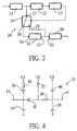
- Fig. 2 shows a block diagram of a path detection device 17, the component the measuring arrangement 2.
- the path detection device 17 contains at least one sensor 18. This can be a passive or active sensor 18. Both Sensor types are mounted near a rotating axis that is proportional to the Move vehicle speed or to the distance covered.
- a passive sensor is, for example, one that works according to the law of induction Sensor.
- a magnetic strip is glued into the rim of a wheel and a sensor attached attached to the axle.
- this passive sensor there is a coil with an iron core. If the wheel is moving, the moving magnetic strip creates one in the coil Induction voltage generated.
- This induction voltage is a sinusoidal voltage, the Frequency and amplitude is speed-dependent.
- speed-dependent frequency in a range between 0.1 Hz and 5 kHz and the speed-dependent amplitude between 1 mV and 50 V.
- Active sensors can e.g. sensors working according to the Hall principle, their Output voltage, however, has a rectangular shape with constant amplitude different frequency.
- a rectangular one supplied by an active sensor Voltage has a type-dependent amplitude between 5 V and 12 V and fluctuates in Dependence on the distance covered, for example in a frequency range between 5 mHz and 2.5 kHz.
- the principle of operation for those working according to the Hall principle Sensors is that an electronic switch is turned on and off by an alternating magnetic field is turned off.
- the 2 shows two sensors 18, their sinusoidal or rectangular ones Output signals are combined in a combination circuit 19.
- the one from the Combination circuit 19 supplied signals are supplied to a converter circuit 20.
- the converter circuit 20 recognizes shortly after the navigation system is switched on and at Start of the journey or after switching off and on again while driving, whether a sine or rectangular signal is output from the combination circuit 19. This becomes a rectangular output signal with a defined maximum amplitude.
- the frequency of the rectangular signals is a measure of the distance covered.
- the rising edges of the converter circuit 20 supplied rectangular signal evaluated.
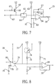
- FIG. 3 A block diagram of the converter circuit 20 is shown in FIG. 3.
- This contains a protective circuit 21, a detector 22, a latch 23, a switch 24, one Amplifier circuit 25 and a comparator circuit 26.
- the protection circuit 21 processed sinusoidal or rectangular signals are the detector 22 and one Input 27 of the switch 24 supplied.
- the detector 22 determines whether it is sine or rectangular signals. Depending on the detection result, shortly after switching on and when starting the journey or after switching off and on while driving the latch 23 is set.
- the latch 23 can store two states. A first one State becomes sinusoidal and a second state rectangular Signal saved. In the first state, the switch 24 couples the input 27 to its first output 28 and in the second state its input 27 with its second output 29.
- the output 28 has an input 30 of the amplifier circuit 25 and the output 29 connected to an input 32 of the comparator circuit 26, which the output signals of Converter circuit 20 provides.
- FIG. 4 An embodiment of the protection circuit 21 is shown in FIG. 4.
- the entrance 33 is connected to a capacitor 34 connected to ground, the cathode of a diode 35 and the Cathode of a diode 36 connected.
- the anode of the diode 35 is on via a resistor 81 laid a first voltage source U1.
- the anode of the diode 36 is via a resistor 37 with a second voltage source U2 and a resistor 38 with a cathode one Diode 39, an anode of a diode 40 and the output 41 of the protection circuit 20 coupled.
- the cathode of the diode 40 is connected to the second voltage source U2 and the anode Diode 39 connected to ground.
- the protection circuit 20 has a decoupling and Limiting function.
- FIG. 5 shows a more detailed circuit diagram of the detector 22.
- the input 42 of the detector 22 is connected to the cathode of a diode 43.
- the anode of diode 43 has one Connection to a capacitor 44 connected to ground, with one to the second Voltage source U2 connected resistor 45 and the inverting input of a Operational amplifier 46.
- the capacitor 44 and the resistor 45 form one Low-pass filter.
- the diode 43 and the resistor 45 perform a signal boost and Decoupling by.
- the non-inverting input of operational amplifier 46, whose Output forms the output of the detector 22 is via a resistor 47 to ground and coupled to the second voltage source U2 via a resistor 48. Resistors 47 and 48 form a voltage divider.
- the capacitor 44 is used for the sinusoidal signals, which the as Comparator to excite operational amplifier 46 to switch, derived to ground become. Such sinusoidal signals which cause the operational amplifier 46 to turn off a certain threshold switches, occur only at higher speeds of the Vehicle and thus at a medium frequency.
- the capacitor 44 must therefore are dimensioned so that all sinusoidal signals which have an amplitude that excite operational amplifier 46 to switch, be derived to ground. hereby but also the higher-frequency rectangular signals are not connected to the Operational amplifier 46 forwarded.
- the latch 23, contains a JK flip-flop 49 and a start circuit 50.
- the clock input T of the JK flip-flop receives the output signal of the detector 22.
- the K input is to ground and the J input to Voltage source U2 laid.
- the output signal of the JK flip-flop 49 is from the Q output removable.
- the reset input R is connected to the start circuit 50.
- This contains an operational amplifier 51 operating as a comparator, the inverting input of which also a resistor 52 connected to ground and one to the voltage source U2 connected resistor 53 and its non-inverting input with a ground connected capacitor 54 and one connected to the voltage source U2 Resistor 55 is connected.
- the Q output of the JK flip-flop 49 has the logical one State "1", which corresponds to voltage U2.
- the JK flip-flop takes this state 49 only when a rectangular signal is present at the input of the detector 22. If a sinusoidal signal is present at the input of the detector 22, the JK flip-flop remains 49 in the on state, i.e. the Q output has the logic state "0".
- the logical one State "0" of the output signal of the JK flip-flop 49 gives the first state of the Hold memory 23 and the logic state "1" of the output signal of the JK trigger 49th indicates the second state of the latch 23.
- the hold memory 23 is designed each time the navigation system is switched on and save a first or second state at the start of the journey. Lies a rectangular signal on, the JK flip-flop remains on regardless of the input signal Clock input T in this state (self-holding). Only when switching off and on again of the navigation system, a new distinction between sine and rectangular signals are made.
- sine and square wave signals at a medium frequency when below a certain Threshold are no longer processed by the detector 22 because they are over the Capacitor 44 are derived to ground.
- This average frequency corresponds, for example the speed of 100 km / h. That means choosing a rectangular one Signal for the latch 23 only with low-frequency signals and thus lower speeds (e.g. below 100 km / h) is possible. At higher A sinusoidal signal is therefore always required for speeds.
- the JK flip-flop 49 is first in the Initial state, i.e. a sinusoidal signal is assumed. That means that too rectangular signals are passed through the amplifier circuit 25, because a No distinction is made at higher speeds. Will the vehicle slower and the frequency thus drops below a determined by the capacitor 44 The JK flip-flop is set, i.e. in this state there will only be one rectangular signal evaluated.
- the Start circuit 50 responsible.
- the resistors 52 and 53 (voltage divider) set the Switching value fixed. Reaches the voltage value at the non-inverting input of the Operational amplifier 51 this switching value, the voltage at the output of the operational amplifier increases 51 from a first to a second value (e.g. from 0 V to 5 V).
- the Switching value is only determined by the value of resistor 55 and the value of Capacitor 54 certain time (charging time constant) reached.
- the charging time constant can e.g. 1 s, i.e. the reset input of the JK flip-flop 49 is approximately 1 s at a first value (e.g. 0 V).
- the two outputs of the JK flip-flop 49 can assume the above-mentioned initial state (Q output on the logic state "0").
- the initial value of the Operational amplifier to the second value (e.g. 5 V), with which the JK flip-flop becomes ready for operation and can react to falling edges at clock input T.
- the central element of the amplifier circuit 25 is an operational amplifier 56, the feedback branch of which is a Contains parallel connection with a capacitor 57 and a resistor 58.
- the exit of the operational amplifier 56 is connected to a terminal of a resistor 59, the another connection forms the output of the amplifier circuit 25.
- the input of the operational amplifier 56 is via a parallel circuit comprising resistor 60 and Capacitor 61 to ground and via a resistor 62 to the second voltage source U2 coupled.
- Via a capacitor 63 and a parallel connection of a resistor 64 and a capacitor 65 becomes a signal from the first output 28 of the changeover switch 24 fed.
- the amplifier circuit 25 amplifies the supplied sinusoidal signal and leads edge detection and band limitation.
- FIG. 8 A more detailed circuit diagram of the comparator circuit 26 is shown in FIG. 8, whose central element is an operational amplifier 69 operating as a comparator.
- Resistor 70 is arranged in the feedback branch of operational amplifier 69, i.e. on Connection of resistor 70 is with the non-inverting input and the other Terminal connected to the output of operational amplifier 69.
- Resistor 70 On Resistor 70 is arranged in the feedback branch of operational amplifier 69, i.e. on Connection of resistor 70 is with the non-inverting input and the other Terminal connected to the output of operational amplifier 69.
- a resistor 71 connected to the second voltage source U2
- a resistor 72 connected to ground and a terminal of a resistor 73 connected.
- the other connection of the resistor 73 is via a switch 74 to the second Voltage source U2 connected.
- the inverting input of operational amplifier 69 is with an input terminal 75 and an output 76 of a further switch 77 connected.
- An input terminal 78 is coupled to ground via a capacitor 79.
- the other input terminal 80 of the switch 77 is with the output of the amplifier circuit 25 connected.
- the switch 74 and the switch 77 are just like that Changeover switch 24 and the transistor 66 from the latch 23 via the output signal, which is output from the Q output of the JK flip-flop controlled.
- the switch 74 In the first state of the latch 23, the switch 74 is open and the switch 77 couples the input 80 with the output terminal 76. This means that signals from the amplifier circuit 25th to the inverting input of the operational amplifier 69.
- the switch 74 In the second state of the latch 23, the switch 74 is closed and the input 78 with the output 76 connected. In the second state, the capacitor 79 connected to ground is thus connected to the inverting input of the operational amplifier 69 connected.
- the switch 74 causes in the first and second state there are different switching hysteresis, which by the resistors 70, 71, 72 and 73 forming a resistance network are determined.
- the switching hysteresis is dimensioned such that largely all disturbances in the supplied rectangular signal are suppressed and processed such supplied rectangular signals, which have a DC component can be.
- the output of the operational amplifier 69 is located rectangular output signals. The distance of the rising or falling Flanks of the rectangular, band and amplitude limited output signal of the comparator circuit 26 is a measure of the distance traveled by the vehicle.
Landscapes
- Engineering & Computer Science (AREA)
- Radar, Positioning & Navigation (AREA)
- Remote Sensing (AREA)
- Physics & Mathematics (AREA)
- General Physics & Mathematics (AREA)
- Automation & Control Theory (AREA)
- Navigation (AREA)
Description
- wenigstens einen Sensor zur Lieferung eines sinus- oder rechteckförmigen Signals in Abhängigkeit des zurückgelegten Weges,
- einen Detektor zur Feststellung der Art des von wenigstens einem Sensor gelieferten Signals wenigstens bis zu einer mittleren Geschwindigkeit, ...
- einen Haltespeicher zur Speicherung eines ersten Zustands bei Detektion eines sinusförmigen Signals und eines zweiten Zustands bei Detektion eines rechteckförmigen Signals,
- eine Verstärkerschaltung zum Empfang des von wenigstens einem Sensor abgeleiteten Signals im ersten Zustand und
- eine Komparatorschaltung (26) zum Empfang des Ausgangssignals der Verstärkerschaltung (25) im ersten Zustand und des von wenigstens einem Sensor (18) abgeleiteten Signals im zweiten Zustand und zur Lieferung eines rechteckförmigen Signals als Maß für den zurückgelegten Weg des Fahrzeugs.
Claims (6)
- Wegeerfassungsvorrichtung (17), diewenigstens einen Sensor zur Lieferung eines sinus- oder rechteckförmigen Signals in Abhängigkeit des zurückgelegten Weges,eine Detektor (22) zur Feststellung der Art des von wenigstens einem Sensor (18) gelieferten Signals wenigstens bis zu einer mittleren Geschwindigkeit,einen Haltespeicher (23) zur Speicherung eines ersten Zustands bei Detektion eines sinusförmigen Signals und eines zweiten Zustands bei Detektion eines rechteckförmigen Signals,eine Verstärkerschaltung (25) zum Empfang des von wenigstens einem Sensor (18) abgeleiteten Signals im ersten Zustand undeine Komparatorschaltung (26) zum Empfang des Ausgangssignals der Verstärkerschaltung (25) im ersten Zustand und des von wenigstens einem Sensor (18) abgeleiteten Signals im zweiten Zustand und zur Lieferung eines rechteckförmigen Signals als Maß für den zurückgelegten Weg des Fahrzeugs enthält.
- Wegeerfassungsvorrichtung (17) nach Anspruch 1, dadurch gekennzeichnet, dass ein Umschalter (24) zum Empfang wenigstens eines von einem Sensor (18) abgeleiteten Signals an seinem Eingang (27) und zur Kopplung seines Eingangs (27) mit seinem ersten Ausgang (28), der mit dem Eingang (30) der Verstärkerschaltung (25) gekoppelt ist, während des ersten Zustands und seines Eingangs (27) mit seinem zweiten Ausgang (29), der mit dem Eingang (32) der Komparatorschaltung (26) gekoppelt ist, während des zweiten Zustands vorgesehen ist.
- Wegeerfassungsvorrichtung (17) nach Anspruch 1, dadurch gekennzeichnet, dass der Detektor (22) einen als Komparator arbeitenden Operationsverstärker (46) enthält, dessen nichtinvertierender Eingang mit einem Spannungsteiler (47, 48) zur Einstellung des Schwellwertes und dessen invertierender Eingang mit einem Tiefpass (44, 45) gekoppelt ist, über den von wenigstens einem Sensor (18) Signale zugeführt werden.
- Wegeerfassungsvorrichtung (17) nach Anspruch 1, dadurch gekennzeichnet, dass der Haltespeicher (23) ein JK-Kippglied (49) enthält, dessen Takteingang zum Empfang des Ausgangssignals des Detektors (22) vorgesehen ist.
- Wegeerfassungsvorrichtung (17) nach Anspruch 1, dadurch gekennzeichnet, dass die Komparatorschaltung (26) einen als Komparator arbeitenden Operationsverstärker enthält, dessen nichtinvertierender Eingang mit einem Widerstandsnetzwerk zur Einstellung einer ersten Schalthysterese während des ersten Zustands und einer zweiten Schalthysterese während des zweiten Zustands verbunden ist.
- Navigationssystem mit einer Wegeerfassungsvorrichtung (17) nach einem der Ansprüche 1 bis 5.
Applications Claiming Priority (3)
| Application Number | Priority Date | Filing Date | Title |
|---|---|---|---|
| DE19750127A DE19750127A1 (de) | 1997-11-13 | 1997-11-13 | Navigationssystem mit einer Wegeerfassungsvorrichtung |
| DE19750127 | 1997-11-13 | ||
| PCT/IB1998/001732 WO1999026043A1 (de) | 1997-11-13 | 1998-10-29 | Navigationssystem mit einer wegeerfassungsvorrichtung |
Publications (2)
| Publication Number | Publication Date |
|---|---|
| EP0951636A1 EP0951636A1 (de) | 1999-10-27 |
| EP0951636B1 true EP0951636B1 (de) | 2004-08-25 |
Family
ID=7848505
Family Applications (1)
| Application Number | Title | Priority Date | Filing Date |
|---|---|---|---|
| EP98949176A Expired - Lifetime EP0951636B1 (de) | 1997-11-13 | 1998-10-29 | Navigationssystem mit einer wegeerfassungsvorrichtung |
Country Status (4)
| Country | Link |
|---|---|
| EP (1) | EP0951636B1 (de) |
| JP (1) | JP2001508549A (de) |
| DE (2) | DE19750127A1 (de) |
| WO (1) | WO1999026043A1 (de) |
Family Cites Families (3)
| Publication number | Priority date | Publication date | Assignee | Title |
|---|---|---|---|---|
| FR2612713B1 (fr) * | 1987-03-20 | 1989-07-07 | Bendix Electronics Sa | Circuit convertisseur de signaux analogiques en signaux logiques |
| FR2612645B1 (fr) * | 1987-03-20 | 1989-05-19 | Bendix France | Procede et dispositif de verification de l'etat de fonctionnement d'un capteur magnetique a reluctance variable et leur application en electronique automobile |
| DE19602243A1 (de) * | 1996-01-23 | 1997-07-24 | Teves Gmbh Alfred | Schaltungsanordnung zur Anpassung eines aktiven Sensors an eine Auswerteschaltung |
-
1997
- 1997-11-13 DE DE19750127A patent/DE19750127A1/de not_active Withdrawn
-
1998
- 1998-10-29 EP EP98949176A patent/EP0951636B1/de not_active Expired - Lifetime
- 1998-10-29 WO PCT/IB1998/001732 patent/WO1999026043A1/de not_active Ceased
- 1998-10-29 DE DE59811868T patent/DE59811868D1/de not_active Expired - Fee Related
- 1998-10-29 JP JP52799199A patent/JP2001508549A/ja active Pending
Also Published As
| Publication number | Publication date |
|---|---|
| DE59811868D1 (de) | 2004-09-30 |
| DE19750127A1 (de) | 1999-05-20 |
| JP2001508549A (ja) | 2001-06-26 |
| EP0951636A1 (de) | 1999-10-27 |
| WO1999026043A1 (de) | 1999-05-27 |
Similar Documents
| Publication | Publication Date | Title |
|---|---|---|
| EP1147375B1 (de) | Verfahren zur leitung eines führers eines fahrzeugs von mindestens einem start- zu mindestens einem zielpunkt | |
| DE10013675B4 (de) | Fahrzeug-Navigationssystem | |
| EP0331675B2 (de) | System zur ausgabe von wegeinformationen für fahrer von landfahrzeugen und informationsausgabesystem | |
| DE69332359T2 (de) | Leitungsgerät für Fahrzeuge | |
| EP1307707B1 (de) | Verfahren zur routenberechnung | |
| DE69725814T2 (de) | Verfahren und Vorrichtung zur Feststellung der Drehung von Rädern | |
| DE102005046177A1 (de) | Fahrzeugnavigationssystem | |
| DE19505487C2 (de) | Einrichtung in einem Fahrzeug zur Bestimmung der aktuellen Fahrzeugposition | |
| DE102007062680A1 (de) | Verkehrsstaugradbestimmungsvorrichtung, Verkehrsstaugradmeldevorrichtung und Programm | |
| EP2420800B1 (de) | Technik zur Signalisierung von Telefonanrufen während einer Routenführung | |
| EP1004851A1 (de) | Adaptives Navigationssystem | |
| DE19606258C1 (de) | Fahrzeugautonome Detektion von Verkehrsstau | |
| DE102011014855A1 (de) | Verfahren und Vorrichtung zum Erfassen und Klassifizieren von fahrenden Fahrzeugen | |
| DE10012502A1 (de) | Fahrzeugnavigationssystem, das Kartendaten über Strassen eingeschränkter Art verwendet | |
| EP0944894B1 (de) | Verfahren zur rechnergestützten navigation eines fahrzeuges mit einem endgerät, endgerät und verkehrszentrale | |
| DE19604892C1 (de) | Positionsbestimmungssystem für Kraftfahrzeuge | |
| EP1072862A1 (de) | Navigationsverfahren und Navigationsgerät | |
| EP0881613B1 (de) | Verfahren zum Erkennen des Zeitpunkts für das Betätigen von Fahrtrichtungssignalleuchten (FRSL) bei Fahrzeugen | |
| DE102006033842A1 (de) | Navigationssystem | |
| EP1192418B1 (de) | Navigationsgerät | |
| DE10053873B4 (de) | Verfahren zur Beeinflussung einer Fahrtroutenführung | |
| DE19945119C2 (de) | Verfahren zum Navigieren eines bodengebundenen Fahrzeugs | |
| EP2201552B1 (de) | Navigationsgerät für kraftfahrzeuge und verfahren zur berechnung und ausgabe mindestens einer alternativen strassenroute im staufall | |
| DE19933639A1 (de) | Verfahren zur Berechnung einer Route von einem Start- zu einem Zielort | |
| DE19753172A1 (de) | Verfahren zur rechnergestützten Navigation eines Fahrzeuges mit einem Endgerät, Endgerät und Verkehrszentrale |
Legal Events
| Date | Code | Title | Description |
|---|---|---|---|
| PUAI | Public reference made under article 153(3) epc to a published international application that has entered the european phase |
Free format text: ORIGINAL CODE: 0009012 |
|
| AK | Designated contracting states |
Kind code of ref document: A1 Designated state(s): DE FR GB |
|
| 17P | Request for examination filed |
Effective date: 19991129 |
|
| RAP1 | Party data changed (applicant data changed or rights of an application transferred) |
Owner name: SIEMENS AKTIENGESELLSCHAFT |
|
| 17Q | First examination report despatched |
Effective date: 20030919 |
|
| GRAP | Despatch of communication of intention to grant a patent |
Free format text: ORIGINAL CODE: EPIDOSNIGR1 |
|
| GRAS | Grant fee paid |
Free format text: ORIGINAL CODE: EPIDOSNIGR3 |
|
| GRAA | (expected) grant |
Free format text: ORIGINAL CODE: 0009210 |
|
| AK | Designated contracting states |
Kind code of ref document: B1 Designated state(s): DE FR GB |
|
| REG | Reference to a national code |
Ref country code: GB Ref legal event code: FG4D Free format text: NOT ENGLISH |
|
| REF | Corresponds to: |
Ref document number: 59811868 Country of ref document: DE Date of ref document: 20040930 Kind code of ref document: P |
|
| GBT | Gb: translation of ep patent filed (gb section 77(6)(a)/1977) |
Effective date: 20041215 |
|
| ET | Fr: translation filed | ||
| PLBE | No opposition filed within time limit |
Free format text: ORIGINAL CODE: 0009261 |
|
| STAA | Information on the status of an ep patent application or granted ep patent |
Free format text: STATUS: NO OPPOSITION FILED WITHIN TIME LIMIT |
|
| 26N | No opposition filed |
Effective date: 20050526 |
|
| PGFP | Annual fee paid to national office [announced via postgrant information from national office to epo] |
Ref country code: GB Payment date: 20071018 Year of fee payment: 10 Ref country code: FR Payment date: 20071022 Year of fee payment: 10 |
|
| PGFP | Annual fee paid to national office [announced via postgrant information from national office to epo] |
Ref country code: DE Payment date: 20071214 Year of fee payment: 10 |
|
| GBPC | Gb: european patent ceased through non-payment of renewal fee |
Effective date: 20081029 |
|
| REG | Reference to a national code |
Ref country code: FR Ref legal event code: ST Effective date: 20090630 |
|
| PG25 | Lapsed in a contracting state [announced via postgrant information from national office to epo] |
Ref country code: DE Free format text: LAPSE BECAUSE OF NON-PAYMENT OF DUE FEES Effective date: 20090501 |
|
| PG25 | Lapsed in a contracting state [announced via postgrant information from national office to epo] |
Ref country code: FR Free format text: LAPSE BECAUSE OF NON-PAYMENT OF DUE FEES Effective date: 20081031 |
|
| PG25 | Lapsed in a contracting state [announced via postgrant information from national office to epo] |
Ref country code: GB Free format text: LAPSE BECAUSE OF NON-PAYMENT OF DUE FEES Effective date: 20081029 |