EP0951344B1 - Method and apparatus for fluid contact - Google Patents
Method and apparatus for fluid contact Download PDFInfo
- Publication number
- EP0951344B1 EP0951344B1 EP98951030A EP98951030A EP0951344B1 EP 0951344 B1 EP0951344 B1 EP 0951344B1 EP 98951030 A EP98951030 A EP 98951030A EP 98951030 A EP98951030 A EP 98951030A EP 0951344 B1 EP0951344 B1 EP 0951344B1
- Authority
- EP
- European Patent Office
- Prior art keywords
- fluid
- cover plate
- tray
- bleed
- over
- Prior art date
- Legal status (The legal status is an assumption and is not a legal conclusion. Google has not performed a legal analysis and makes no representation as to the accuracy of the status listed.)
- Expired - Lifetime
Links
- 239000012530 fluid Substances 0.000 title claims abstract description 196
- 238000000034 method Methods 0.000 title claims description 13
- 238000012546 transfer Methods 0.000 claims description 23
- 238000006073 displacement reaction Methods 0.000 claims description 4
- 239000007788 liquid Substances 0.000 description 17
- 239000007789 gas Substances 0.000 description 9
- 238000012360 testing method Methods 0.000 description 8
- 239000006185 dispersion Substances 0.000 description 7
- 238000005194 fractionation Methods 0.000 description 7
- KFZMGEQAYNKOFK-UHFFFAOYSA-N Isopropanol Chemical compound CC(C)O KFZMGEQAYNKOFK-UHFFFAOYSA-N 0.000 description 6
- OKKJLVBELUTLKV-UHFFFAOYSA-N Methanol Chemical compound OC OKKJLVBELUTLKV-UHFFFAOYSA-N 0.000 description 6
- XLYOFNOQVPJJNP-UHFFFAOYSA-N water Substances O XLYOFNOQVPJJNP-UHFFFAOYSA-N 0.000 description 6
- 230000000712 assembly Effects 0.000 description 5
- 238000000429 assembly Methods 0.000 description 5
- 238000011144 upstream manufacturing Methods 0.000 description 4
- 229920003023 plastic Polymers 0.000 description 3
- 239000004033 plastic Substances 0.000 description 3
- 230000001154 acute effect Effects 0.000 description 2
- 230000008859 change Effects 0.000 description 2
- 238000010276 construction Methods 0.000 description 2
- 230000000694 effects Effects 0.000 description 2
- 238000005516 engineering process Methods 0.000 description 2
- 238000009434 installation Methods 0.000 description 2
- 230000003993 interaction Effects 0.000 description 2
- 239000000463 material Substances 0.000 description 2
- 238000010521 absorption reaction Methods 0.000 description 1
- 230000001174 ascending effect Effects 0.000 description 1
- 230000015572 biosynthetic process Effects 0.000 description 1
- 230000005587 bubbling Effects 0.000 description 1
- 238000006243 chemical reaction Methods 0.000 description 1
- 230000007423 decrease Effects 0.000 description 1
- 230000003247 decreasing effect Effects 0.000 description 1
- 230000001419 dependent effect Effects 0.000 description 1
- 238000004821 distillation Methods 0.000 description 1
- 230000002708 enhancing effect Effects 0.000 description 1
- 238000007667 floating Methods 0.000 description 1
- 239000007792 gaseous phase Substances 0.000 description 1
- 230000005484 gravity Effects 0.000 description 1
- 239000012535 impurity Substances 0.000 description 1
- 239000007791 liquid phase Substances 0.000 description 1
- 239000002184 metal Substances 0.000 description 1
- 239000003595 mist Substances 0.000 description 1
- 239000000203 mixture Substances 0.000 description 1
- 238000012986 modification Methods 0.000 description 1
- 230000004048 modification Effects 0.000 description 1
- 238000000465 moulding Methods 0.000 description 1
- 239000002245 particle Substances 0.000 description 1
- 230000002028 premature Effects 0.000 description 1
- 230000037452 priming Effects 0.000 description 1
- 230000008569 process Effects 0.000 description 1
- 230000000630 rising effect Effects 0.000 description 1
- 238000000926 separation method Methods 0.000 description 1
- 230000007704 transition Effects 0.000 description 1
Images


Classifications
-
- B—PERFORMING OPERATIONS; TRANSPORTING
- B01—PHYSICAL OR CHEMICAL PROCESSES OR APPARATUS IN GENERAL
- B01F—MIXING, e.g. DISSOLVING, EMULSIFYING OR DISPERSING
- B01F23/00—Mixing according to the phases to be mixed, e.g. dispersing or emulsifying
- B01F23/20—Mixing gases with liquids
-
- B—PERFORMING OPERATIONS; TRANSPORTING
- B01—PHYSICAL OR CHEMICAL PROCESSES OR APPARATUS IN GENERAL
- B01D—SEPARATION
- B01D3/00—Distillation or related exchange processes in which liquids are contacted with gaseous media, e.g. stripping
- B01D3/14—Fractional distillation or use of a fractionation or rectification column
- B01D3/16—Fractionating columns in which vapour bubbles through liquid
- B01D3/163—Plates with valves
Definitions
- This invention relates to a fluid dispersing apparatus and to a method of providing a mass transfer exchange system.
- This apparatus and this method particularly pertain to a novel valve assembly for use in fractionation columns and other related apparatus.
- a number of horizontally oriented surfaces or trays are mounted in a sealed, vertically oriented vessel known in the industry as a column or tower.
- Each of the trays may contain numerous openings.
- a relatively heavier fluid is introduced on the upper surface of the uppermost tray deck. The introduction of this fluid at one end of the horizontal tray is referred to as the upstream end or portion.
- a crossflow forms as the fluid flows across from the upstream end of the tray to the downstream end or portion of each tray.
- a weir which leads to a downcomer.
- the downcomer of an upper tray leads down to an unperforated upstream area or downcomer seal area on the next lower tray.
- a lighter fluid is introduced into the lower end of the column. As the heavier liquid flows across the tray surface, the lighter fluid ascends through the openings in the trays and into the heavier fluid flowing across and above the surface of the tray to create a bubble or active area where there is intimate and active contact between the heavier and lighter fluids.
- Some columns utilize multiple sets of flow paths including a downcomer, active area and downcomer seal transition area for each section.
- valves associated within the tray openings and others have fixed assemblies over the holes or apertures.
- the valves may consist of generally flat plates or bubble caps to deflect the rising gases. These valves rise upwardly and fall due to gravity by the introduction of fluid pressure from below the valve.
- each individual valve introduces a small area of blockage across the each aperture of the tray deck thereby reducing the interaction or exchange between the fluids. This small, central area above each valve is a stagnant zone or an inactive area where minimal mass transfer exchange occurs.
- FR 1,439,459 discloses a fluid dispersing apparatus comprising column like vents.
- US 3,399,871 discloses a bubbling valve for liquid-phase and gaseous-phase exchange consisting of a relative thin disc formed with rectilinear slots disposed tangentially on a circle concentric to the disc and adapted to reduce priming and provide a self-centering effect.
- US 3,427,007 discloses a gas and liquid contact apparatus having a bubble tower plate adapted to carry a liquid and formed with an opening through which a gas or vapour is adapted to flow upwardly through the plate to contact the liquid.
- SU 766609 discloses a fluid dispersing apparatus.
- US 4,290,981 discloses an exchange element for the bottoms of an exchanger column comprising a cylinder having grid openings into the side walls, a fix cover plate at the top of the cylinder for defecting gas and a moveable aperture valve plate inside the cylinder normally covering the opening in the exchange bottoms.
- SU 959798 discloses a fluid dispersing apparatus.
- SU 1012939 discloses a fluid dispersing apparatus.
- This invention relates to a fluid dispersing apparatus of the type used in distillation and absorption systems for mass transfer exchange between two fluids of differing masses. According to an aspect of the present invention, there is provided a fluid dispersing apparatus, comprising:
- the cover plate is positioned over the tray opening to provide a fluid escape passage between the cover plate and a tray deck surface. Lighter fluid flows upwardly through the tray opening between the tray deck and the cover plate while heavier fluid flows across the tray deck surface.
- a bleed fluid deflecting member spans the fluid perforation
- a bleed fluid deflecting member spans the fluid perforation from side-to-side to provide at least two oppositely facing outlets.
- the configuration of the deflecting member disperses the fluid into two distinct bleed fluid streams which flow away from one another and passes over a central zone of the cover plate. These two bleed fluid streams are different in size from the fluid that passes between the cover plate and the tray deck at the fluid escape passage.
- a method of providing a mass transfer exchange system comprising; providing a valve assembly having a cover plate and means to position the cover plate over a tray opening in a tray deck of said mass transfer exchange system to define a fluid escape passage between the tray opening and the tray deck; perforating said cover plate of the valve assembly to form at least one bleed fluid perforation in the cover plate; and forming an integral deflecting member over said fluid perforation from side-to- side to provide at least two oppositely facing outlets such that is in use at least two distinct bleed fluid streams flow away from one another over a central portion of said cover plate, wherein each distinct bleed fluid stream differs in size from a fluid stream flowing upwardly through the fluid escape passage, and wherein one said bleed fluid stream is directed toward a central portion of said cover plate.
- the apparatus is a valve assembly and the cover plate rests over the tray thereunder by means of slidable legs. At least two legs are provided to slide in and extend. downwardly in the tray opening. For each leg, at least one tray engaging projection is provided on that leg to limit the upward displacement of the cover plate when the upwardly flowing vapor pressure pushes against the cover plate. This defines fluid escape passages between the cover plate and the tray deck.
- At least two perforations are provided and the legs are at positions that lie between the perforations but are spaced outwardly therefrom, on the cover plate.
- the or each bleed fluid deflecting member may be a hump bridge over the fluid opening.
- the or each hump bridge may be a portion of the cover plate which has been formed by providing pairs of parallel slits in the cover plate and upwardly pressing the portion of the cover plate between the slits to provide the perforation there/below leading to the oppositely facing outlets on each side thereof.
- Three perforations with deflecting members may be provided, and in plan view, they may be arranged in a V-formation around the center of the cover plate with the deflecting member hump bridges extending along parallel, spaced paths.
- the cover plate legs may be along paths which extend from the center of the cover plate, between the three deflecting members.
- the or each deflecting member may be a portion of the cover plate which has been formed by providing pairs of parallel slits in the cover plate and upwardly pressing portions of the cover plate on the outer sides of the or each pair of parallel slits to provide the perforations there/below leading to oppositely facing outlets on each side thereof.
- the valve assembly of the present invention provides for a finer dispersion of the lighter fluid over a traditionally inactive area of the valve assembly. This provides for a greater active area than conventional tray assemblies which rely on traditional valve configurations thereby increasing the efficiency of the mass transfer and thus, lowering the energy requirements. More efficient mass transfer allows for a decreased energy requirement for the entire mass transfer exchange system while increasing the efficiency and maintaining the purity of the desired products.
- the term "fluid” is adopted from the terminology of mass transfer applications, in order to describe generally, without restriction to mass transfer technology, the kind of particulates that would flow through the valve of the present invention.
- the particulates in mass transfer operations generally consist of droplets or bubbles at the molecular level or on a microscopic scale.
- vapor or "gas” is a lighter fluid
- liquid is a heavier fluid.
- the dispersion tray valve of the present invention is ideally utilized in a high fluid pressure environment, such as in a trayed tower column. This high fluid pressure environment allows for the separation or fractionation of vapors, gases and liquids.
- tray and "tray deck” refer to the surface within a tower column used in mass transfer applications.
- the tray may also be described as a fluid contacting fractionation tray. In a typical tray installation, the upper surface of the tray is toward the top of the tower and the lower surface of the tray is toward the bottom of the tower. Many different trays may be contained within a trayed or fractionation column.
- tray openings are positioned throughout the tray deck surface. Ordinarily, valves or other devices are positioned above the tray openings to regulate the flow of vapors through the liquids.
- the term tray herein means simply any surface through which a valve, such as in the present invention, is mounted.
- valve assembly or other device of the present invention may be constructed to fit within the mass transfer fractionation trays.
- the dispersion tray valve is illustrated, described and claimed, generically and in preferred specific embodiments.
- valve assembly or other device of the present invention is preferably inserted into the openings of the trays for use in a tower column and fluid environment. However, it is not intended to restrict the application of the invention to a valve for use in only a fluid environment or a tower column.
- valve assembly or other device of the present invention preferably moves in an upward and downward motion relative to the tray deck. This movement allows for the fluid to pass from one side of the tray deck to the other side to accomplish the fractionation of fluids required by mass transfer technology.
- the distance between the tray deck and the dispersion valve defines a fluid escape passage or opening where upwardly flowing particles pass through.
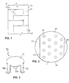
- FIG. 1 and 2 there is shown, in simple schematics, a vertical oriented tower or column 50 and an above view of a tray deck 1.
- a number of tray decks 1 are horizontally spaced apart and mounted within column 50. Liquid is fed to the uppermost tray deck by a fluid line 61 at an upstream end 56 of the tray deck. Downcomer passages 65 lead down from one tray deck to the next lower tray deck at downstream end 57.
- a lighter fluid or vapor is introduced at the bottom of the tower through feed line 62. As the heavier liquid flows across the tray deck surface 1, the vapor ascends through the openings 10 in the tray to create a bubble or active area 55. In the active area 55, intimate and active contact occurs between the heavier fluid and lighter vapor.
- FIG. 3 shows a prior art valve assembly 70 of conventional construction.
- Valve assembly 70 is mounted in openings 10 of the tray deck 1.
- the valve 70 includes a non-perforated cover plate 71 with legs 73, 73A and 73B to allow the valve to be mounted within tray deck 1.
- a fluids contacting column, tray opening 10, fluid dispersing assembly, generally designated 18, comprising:
- the assembly 18 is a valve assembly and the cover plate 21 rests on the tray over the opening 10 thereunder, the legs 23, 23A and 23B are slidable, in and extending downwardly in the tray opening 10, and, for each leg 23, 23A and 23B, at least one tray engaging projection, 230, 230A and 230B respectively, is provided on that leg 23, 23A and 23B for limiting cover plate upward displacement, by upwardly flowing fluid, to reveal the escape passages such as that designated 20.
- three perforations 200, 201 and 202 are provided, and the legs, 23, 23A and 23B, are at positions that lie between the perforations, 200, 201 and 202, but are spaced outwardly therefrom, on the cover plate 21.
- the bleed fluid perforations are arranged in a V-shaped formation such that the fluid streams pass over a traditionally inactive and central area of the valve Z.
- the legs 23, 23A and 23B prevent lateral displacement of the cover plate 21 over the tray 1.
- the valve assembly 18 is made from a material, preferably metal, that will be suitable for the fluids contacting application with which the column (not shown) is intended to be used.
- the valve may be constructed of other materials such as plastics when the valve assembly is to be used in mass transfer applications when the fluids do not interact with the plastic. Valves constructed of plastic lower the cost of the equipment for the column.
- the cover plate 21 is circular, for covering a circular opening 10, and the three legs 23, 23A and 23B, are integral therewith and are circumferentially spaced therearound at 120 degrees from one another to lie along paths which extend from the center of the cover plate 21, between the deflecting members 224, 225 and 226.
- the tray engaging projections 230, 230A and 230B are described in Provisional Patent Application, Serial No. 60/061,504, filed October 10, 1997 by Karl T. Chuang entitled “Method and Apparatus for Tray Valve Attachment”.
- tray engaging projections Two types of tray engaging projections are shown, which are:
- the distance 15 between the upper end of the tray engaging projection 230 and the cover plate 21 determines the maximum height of the escape passage 110 when the cover plate 21 is fully displaced by being floated upwardly by lighter fluid to the position shown in Figure 5.
- the tray opening 10 may be provided with at least one anti-rotation tab, such as that designated 1A, Figure 4.
- the tab la protrudes slightly inwardly, radially from the perimeter of the tray opening 10 so that when leg 23 is in the opening 10 rotation of the cover plate 21 in the opening 10 is restricted. This facilitates a more uniform passage of fluid through all of the escape passages, such as that designated 110, and ensures a more predictable fluid flow rate calculations to be made to achieve higher efficiency.
- Anti-sticking tabs such as that designated 24 in Figures 4, 5 and 6, protrude slightly downwardly form the cover plate 21.
- the tabs 24 ensure that there is always a gap between the underside of the cover plate 21 and the tray 1. This avoids the cover plate 21 becoming completely suction attached to the tray deck 1 during use so that the cover plate 21 may be floated.
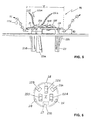
- the bleed fluid deflecting members 224, 225 and 226 may be described as hump bridges, sun roof projections or canopies providing bleed fluid openings, such as those designated 22 on opposite sides of the bleed fluid deflecting members 224, 225, and 226.
- the three bleed fluid deflecting members 224, 225 and 226 when viewed from above are in a V-formation around the center of the cover plate 21, and extend upwardly over in and span the perforations 200, 201 and 202 from side-to-side, along parallel, spaced paths, and may be provided by cutting parallel slits in the cover plate 21 and either upwardly pressing the portion of the cover plate 21 between the lists by stamping, or molding, an upwardly curved bridge or canopy to provide the perforations 200, 201 and 202, with the bleed fluid deflecting members 224, 225, and 226 spanning them.
- the tray opening 10 and the cover plate 21 including the perforations 200, 201 and 202 may be other geometric shapes such as round, square or triangular. While three perforations 200, 201 and 202 are provided in this embodiment, the number, size and configuration of the perforations and the bleed fluid openings, such as those designated 22, will be determined by the size of the openings 10 in the tray 1, and the dispersed fluid dispersion effect desired.
- a relatively heavier fluid stream flows over the top of the tray 1, in the direction of arrow X, while a relatively lighter fluid 11 flows upwardly through the opening 10 ( Figure 4) lifting the assembly 1 to reveal the escape passages, such as that designated 10.
- a portion of the lighter fluid 11 passing through the opening 10 escapes as streams of relatively large droplets or bubbles 110 and 110A from the fluid escape passages 20, such as that designated 10, into the heavier stream, while another portion thereof passes upwardly through the perforations 200, 201 and 202 to be deflected by the deflecting members 224, 225 and 226, as two emerging streams of relatively finer bubbles, 220 and 220A into the heavier streams, from the oppositely facing outlets, such as those designated 22 and 22A.
- the streams of finer bubbles 220 and 220 A flow in opposite directions, away from one another, form the outlets, such as those designated 22 and 22A, over the cover plate 21 before ascending through the heavier liquid.
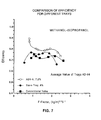
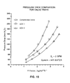
- isopropyl alcohol-rich vapor was pumped upwardly, as the lighter fluid, through a column containing the tray while methyl alcohol liquid was passed downwardly through the column, as the heavier fluid, to flow across the tray. This was done for the exchange of mass and heat between vapor and liquid at various liquid flow rates of 0.12 GPM/(inch weir length) to 0.59 GPM/(inch weir length) for the isopropyl alcohol/methyl alcohol system. In an air-water column a constant liquid flow rate of 0.29 GPM/(inch weir length) was applied.
- F represents the square root of kinetic energy of the vapor for a superficial vapor velocity of 0.46 m/s to 2.3 m/s
- E represents the exchange efficiency, that is, as a ration of the change of composition of the tray to the change that would occur on a theoretical tray.
- -•- represents a conventional tray with 8% of the tray surface area perforated and with cover plates containing no perforations.
- - ⁇ - represents the tray of -•- with cover plate perforated
- -o- represents the tray of -•- with the cover plate having perforations and deflecting members as shown in Figures 4 and 5 according to the present invention.
- valve assembly of Figures 4 and 5 offers approximately a 10% increase in efficiency over the conventional tray at the normal operating range of the flows tested.
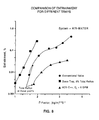
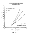
- test column 300 mm diameter which has three trays installed and the middle tray serves as the test tray.
- Manometer taps were placed above and below the test tray to measure the dry or total tray pressure drop.
- the top tray was used to collect the entrainment which was measured by recording the time elapsed to fill a container.
- the top tray was also covered with a 30-mm layer of mist eliminator mesh to ensure that the entrained water was not carried out of the column.
- the bottom tray was designed as an air distributor and a weeping collector.
- the water pressure drop for the assembly shown in Figures 4 and 5 is approximately 10 to 20% lower than those of conventional valve assemblies of Figure 3, depending on the flow rates of the fluids.
- the assembly as shown in Figures 4 and 5 was found to be able to provide a greater escape over the lighter fluid to pass upwardly through a tray than that of conventional trays.
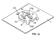
- a cover plate 121 is attached to the tray 1 by three downwardly extending cover plate legs, two of which are shown and designated 123 and 123A.
- the legs such as 123 and 123A are spaced equidistant from one another around the cover plate 121, and secure the cover plate 121 in a fixed, raised position over opening 10 in the tray 1 to provide escape passages 124 to 126, between the tray 1 and cover plate 121, for upwardly flowing fluid through the opening 10.
- Three bleed fluid perforations 100, 100A and 100B are provided in the cover plate 121, each having a bleed fluid deflecting member 122, 122A and 122B, respectively, spanning that perforation 100, 100A and 100B, to provide oppositely facing outlets, such as, 128 and 128A.
- the cover plate 121, legs such as 123 and 123A, and members 122, 122A and 122B may be integral with the tray deck and pressed therefrom. In other embodiments, the cover plate 121, legs such as 123 and 123A, and members 122, 122A and 122B may be integral, and pressed from sheet, mounted in the tray 1 by springing the legs into the opening 10 until projections (not shown) secure the cover plate 121 at a fixed height over the opening 10.
- the assembly shown in Figure 12 operates in the same manner as that described with reference to Figures 4 and 5, except that the cover plate 121 is fixed in position over the opening 10 and is not lifted by the relatively lighter fluid.
- the perforations with deflecting members may be incorporated into any other configurations of valve cover plates or caps such as square, rectangular, triangular or other shapes as required by the specifications of the tower.
- different shapes and numbers of perforations and deflecting members may be incorporated into various valves.
- the perforations with the deflecting members may be incorporated into various valves.
- the perforations with the deflecting members may be adapted and used with other traditional valve designs such as other floating valves and other fixed valves such as bubble caps to increase the surface area contact between the lighter and heavier fluids and produce finer fluid droplets and bubbles as needed.
Landscapes
- Chemical & Material Sciences (AREA)
- Chemical Kinetics & Catalysis (AREA)
- Vaporization, Distillation, Condensation, Sublimation, And Cold Traps (AREA)
- Physical Or Chemical Processes And Apparatus (AREA)
- Extraction Or Liquid Replacement (AREA)
- Sampling And Sample Adjustment (AREA)
Applications Claiming Priority (3)
| Application Number | Priority Date | Filing Date | Title |
|---|---|---|---|
| US6150497P | 1997-10-10 | 1997-10-10 | |
| US61504P | 1997-10-10 | ||
| PCT/US1998/021394 WO1999019054A1 (en) | 1997-10-10 | 1998-10-09 | Method and apparatus for fluid contact |
Publications (3)
| Publication Number | Publication Date |
|---|---|
| EP0951344A1 EP0951344A1 (en) | 1999-10-27 |
| EP0951344A4 EP0951344A4 (en) | 2001-09-12 |
| EP0951344B1 true EP0951344B1 (en) | 2003-09-03 |
Family
ID=22036212
Family Applications (1)
| Application Number | Title | Priority Date | Filing Date |
|---|---|---|---|
| EP98951030A Expired - Lifetime EP0951344B1 (en) | 1997-10-10 | 1998-10-09 | Method and apparatus for fluid contact |
Country Status (10)
| Country | Link |
|---|---|
| US (2) | US6145816A (enExample) |
| EP (1) | EP0951344B1 (enExample) |
| JP (1) | JP2001505823A (enExample) |
| KR (1) | KR100504992B1 (enExample) |
| CN (1) | CN1104941C (enExample) |
| AT (1) | ATE248641T1 (enExample) |
| CA (1) | CA2274697C (enExample) |
| DE (1) | DE69817762T2 (enExample) |
| ES (1) | ES2206998T3 (enExample) |
| WO (1) | WO1999019054A1 (enExample) |
Cited By (1)
| Publication number | Priority date | Publication date | Assignee | Title |
|---|---|---|---|---|
| RU2500452C2 (ru) * | 2009-07-24 | 2013-12-10 | Александр Максимович Журба | Колонна ректификационная с колпачковыми тарелками |
Families Citing this family (30)
| Publication number | Priority date | Publication date | Assignee | Title |
|---|---|---|---|---|
| US6145816A (en) * | 1997-10-10 | 2000-11-14 | Amt International, Inc. | Fluids contacting, tray opening, fluid dispersing assembly |
| US6588736B1 (en) * | 2000-12-14 | 2003-07-08 | Karl T. Chuang | Gas/liquid contacting, perforated tray assembly |
| US6799752B2 (en) * | 2001-05-03 | 2004-10-05 | Amt International, Inc. | Method and apparatus for improving a fractionation process |
| US20050280169A1 (en) * | 2004-06-21 | 2005-12-22 | China Petroleum & Chemical Corporation | Gas-liquid contact tray with fixed valves for mass transfer |
| CN1327924C (zh) * | 2004-07-19 | 2007-07-25 | 南京大学 | 母子导向浮阀 |
| PL1747809T3 (pl) * | 2005-07-29 | 2008-09-30 | Sulzer Chemtech Ag | Zawór denny do kolumny półkowej |
| US7540476B2 (en) * | 2006-07-18 | 2009-06-02 | Sulzer Chemtech Ag | Valve for a contact tray |
| US8540218B2 (en) * | 2007-04-27 | 2013-09-24 | Gtc Technology Us Llc | Fluid dispersion unit assembly and method |
| US8517354B1 (en) | 2008-03-20 | 2013-08-27 | Gtc Technology Us Llc | Fluid dispersion unit with directional component vector |
| US9463397B2 (en) | 2008-04-04 | 2016-10-11 | Gtc Technology Us Llc | System and method for liquid distribution |
| US8517352B1 (en) | 2008-04-04 | 2013-08-27 | Gtc Technology Us Llc | Liquid distributor |
| US8678357B2 (en) | 2010-05-17 | 2014-03-25 | Gtc Technology Us, Llc | Fluid contactor-diffuser tray assembly |
| US8480062B2 (en) * | 2009-05-15 | 2013-07-09 | Gtc Technology Us, Llc | Activated hinge-joint |
| US9199206B2 (en) * | 2010-05-11 | 2015-12-01 | Sulzer Chemtech Ag | Contact tray for a mass transfer column |
| US8944419B2 (en) * | 2010-05-11 | 2015-02-03 | Sulzer Chemtech Ag | Contact tray for a mass transfer column |
| US9072986B2 (en) | 2011-02-23 | 2015-07-07 | Gtc Technology Us Llc | Method and apparatus for securing fractionation trays |
| US9597650B2 (en) | 2011-04-18 | 2017-03-21 | Gtc Technology Us Llc | System for improved reactant mixing and distribution |
| US12059640B2 (en) * | 2014-08-11 | 2024-08-13 | Sulzer Management Ag | Method and system for orifice control of valve pressure drop |
| MX378167B (es) * | 2014-12-23 | 2025-03-10 | Sulzer Management Ag | Diseño de aberturas para bandeja de contacto vapor-liquido. |
| US9850166B2 (en) | 2015-02-03 | 2017-12-26 | Construction Research & Technology, Gmbh | Liquid coloring suspension and colored cementitious composition |
| US20170007943A1 (en) * | 2015-07-08 | 2017-01-12 | Koch-Glitsch, Lp | Contact tray for a mass transfer column and method involving same |
| CN107820443B (zh) | 2015-07-08 | 2021-05-04 | 科氏-格利奇有限合伙公司 | 用于传质塔的接触阀塔盘 |
| US9981235B2 (en) * | 2016-01-28 | 2018-05-29 | Woven Metal Products, Inc. | Tray deck orifice device and methods of repairing a tray deck |
| USD816188S1 (en) | 2016-06-07 | 2018-04-24 | Koch-Glitsch, Lp | Tray valve cover |
| USD816189S1 (en) | 2016-06-07 | 2018-04-24 | Koch-Glitsch, Lp | Tray valve |
| MY208421A (en) * | 2017-12-27 | 2025-05-08 | Koch Glitsch Lp | Contact tray for a mass transfer column |
| US11420135B2 (en) * | 2018-08-06 | 2022-08-23 | Koch-Glitsch, Lp | Multi-pass contact tray for a mass transfer column and method involving same |
| USD898165S1 (en) * | 2018-12-19 | 2020-10-06 | Koch-Glitsch, Lp | Tray valve |
| CN110420475A (zh) * | 2019-08-21 | 2019-11-08 | 姚传亮 | 一种板式分馏塔 |
| CA3223704A1 (en) * | 2021-07-14 | 2023-01-19 | Marco RYLL | Valve trays in extraction columns |
Family Cites Families (17)
| Publication number | Priority date | Publication date | Assignee | Title |
|---|---|---|---|---|
| BE620721A (enExample) * | 1960-09-30 | 1900-01-01 | ||
| FR1439459A (fr) * | 1964-06-27 | 1966-05-20 | Kralovoplska Strojirna Zd Y Ch | Plateau pour colonnes de fractionnement et colonne pourvue de plateaux conformes au précédent |
| FR1452216A (fr) * | 1965-07-28 | 1966-02-25 | Loire Atel Forges | Clapet de barbotage pour appareils d'échange entre une phase gazeuse et une phase liquide |
| GB1186883A (en) * | 1966-02-21 | 1970-04-08 | Chepos Zd Y Chemickeho A Potra | Fluid Contacting Apparatus |
| FR1603103A (enExample) * | 1968-05-09 | 1971-03-22 | ||
| US3747905A (en) * | 1970-11-10 | 1973-07-24 | Pantaleoni N | Contact apparatus and method |
| US3815880A (en) * | 1972-11-27 | 1974-06-11 | Phillips Petroleum Co | Valve mechanism for fluid contact apparatus |
| US4118446A (en) * | 1974-08-30 | 1978-10-03 | Viktor Leontievich Burin | Valve tray for mass-exchange apparatus |
| US4225541A (en) * | 1977-12-20 | 1980-09-30 | Vaschuk Valery I | Contact tray for mass and heat exchange apparatus |
| SU766609A1 (ru) * | 1978-03-27 | 1980-09-30 | Предприятие П/Я В-8333 | Клапанна тарелка |
| DE2848386A1 (de) * | 1978-11-08 | 1980-05-14 | Stahl App & Geraetebau Gmbh | Austauschelement fuer boeden in stoffaustauschkolonnen |
| SU1012939A1 (ru) * | 1980-07-11 | 1983-04-23 | Казахский Химико-Технологический Институт | Клапанна тарелка |
| US4344900A (en) * | 1980-10-16 | 1982-08-17 | Phillips Petroleum Company | Fractionator tray valve |
| SU959798A1 (ru) * | 1981-02-18 | 1982-09-23 | Московский Ордена Октябрьской Революции И Ордена Трудового Красного Знамени Институт Нефтехимической И Газовой Промышленности Им.И.М.Губкина | Клапанна тарелка |
| BR9807653A (pt) * | 1997-02-05 | 2000-02-15 | Norton Chem Process Prod | Dispositivo aperfeiçoado para transferência de massa |
| KR20000069416A (ko) * | 1997-10-10 | 2000-11-25 | 에이엠티 인터내셔널 인코포레이티드 | 트레이 밸브 부착을 위한 장치 및 방법 |
| US6145816A (en) * | 1997-10-10 | 2000-11-14 | Amt International, Inc. | Fluids contacting, tray opening, fluid dispersing assembly |
-
1998
- 1998-09-01 US US09/145,187 patent/US6145816A/en not_active Expired - Lifetime
- 1998-10-09 DE DE69817762T patent/DE69817762T2/de not_active Expired - Fee Related
- 1998-10-09 CA CA002274697A patent/CA2274697C/en not_active Expired - Fee Related
- 1998-10-09 ES ES98951030T patent/ES2206998T3/es not_active Expired - Lifetime
- 1998-10-09 EP EP98951030A patent/EP0951344B1/en not_active Expired - Lifetime
- 1998-10-09 CN CN98802384A patent/CN1104941C/zh not_active Expired - Fee Related
- 1998-10-09 KR KR10-1999-7005187A patent/KR100504992B1/ko not_active Expired - Lifetime
- 1998-10-09 WO PCT/US1998/021394 patent/WO1999019054A1/en not_active Ceased
- 1998-10-09 AT AT98951030T patent/ATE248641T1/de not_active IP Right Cessation
- 1998-10-09 JP JP52248899A patent/JP2001505823A/ja not_active Ceased
-
2000
- 2000-02-15 US US09/504,291 patent/US6270062B1/en not_active Expired - Lifetime
Cited By (1)
| Publication number | Priority date | Publication date | Assignee | Title |
|---|---|---|---|---|
| RU2500452C2 (ru) * | 2009-07-24 | 2013-12-10 | Александр Максимович Журба | Колонна ректификационная с колпачковыми тарелками |
Also Published As
| Publication number | Publication date |
|---|---|
| DE69817762T2 (de) | 2004-08-19 |
| CA2274697C (en) | 2006-12-19 |
| DE69817762D1 (de) | 2003-10-09 |
| CA2274697A1 (en) | 1999-04-22 |
| US6270062B1 (en) | 2001-08-07 |
| EP0951344A1 (en) | 1999-10-27 |
| WO1999019054A1 (en) | 1999-04-22 |
| ES2206998T3 (es) | 2004-05-16 |
| CN1247482A (zh) | 2000-03-15 |
| EP0951344A4 (en) | 2001-09-12 |
| ATE248641T1 (de) | 2003-09-15 |
| KR100504992B1 (ko) | 2005-08-01 |
| KR20000069415A (ko) | 2000-11-25 |
| JP2001505823A (ja) | 2001-05-08 |
| US6145816A (en) | 2000-11-14 |
| CN1104941C (zh) | 2003-04-09 |
Similar Documents
| Publication | Publication Date | Title |
|---|---|---|
| EP0951344B1 (en) | Method and apparatus for fluid contact | |
| US3080155A (en) | Flow control means | |
| US3087711A (en) | Fluid contact trays | |
| CA2157627C (en) | Contact tray apparatus and method | |
| US5120474A (en) | Valve-tray assembly | |
| US6053485A (en) | Apparatus for tray valve attachment | |
| EP1015087B1 (en) | Improved mass transfer device | |
| US5454989A (en) | Vapor-liquid contact apparatus | |
| KR101386106B1 (ko) | 가스-액체 접촉 장치 | |
| US3125614A (en) | Figure | |
| CA1127068A (en) | Mass transfer equipment | |
| US4547326A (en) | Gas liquid contacting tray | |
| US6193222B1 (en) | Gas-liquid contact tray and method | |
| US20160038851A1 (en) | Method and system for orifice control of valve pressure drop | |
| US6189872B1 (en) | Froth activator apparatus and method | |
| KR101304184B1 (ko) | 기체-액체 접촉기 배플 | |
| US4810428A (en) | High efficiency radial type vapor distributor for packed towers | |
| CA2194580C (en) | Vapor-liquid contact apparatus | |
| AU1451799A (en) | High-capacity vapor/liquid contacting device | |
| EP0059449A1 (en) | Improved gas-liquid contacting tray | |
| WO2018140751A1 (en) | Method and system for orifice control of valve pressure drop |
Legal Events
| Date | Code | Title | Description |
|---|---|---|---|
| PUAI | Public reference made under article 153(3) epc to a published international application that has entered the european phase |
Free format text: ORIGINAL CODE: 0009012 |
|
| 17P | Request for examination filed |
Effective date: 19990709 |
|
| AK | Designated contracting states |
Kind code of ref document: A1 Designated state(s): AT BE CH CY DE DK ES FI FR GB GR IE IT LI LU MC NL PT SE |
|
| A4 | Supplementary search report drawn up and despatched |
Effective date: 20010802 |
|
| AK | Designated contracting states |
Kind code of ref document: A4 Designated state(s): AT BE CH CY DE DK ES FI FR GB GR IE IT LI LU MC NL PT SE |
|
| RIC1 | Information provided on ipc code assigned before grant |
Free format text: 7B 01F 3/04 A, 7B 01D 3/16 B |
|
| 17Q | First examination report despatched |
Effective date: 20020610 |
|
| GRAH | Despatch of communication of intention to grant a patent |
Free format text: ORIGINAL CODE: EPIDOS IGRA |
|
| GRAS | Grant fee paid |
Free format text: ORIGINAL CODE: EPIDOSNIGR3 |
|
| GRAA | (expected) grant |
Free format text: ORIGINAL CODE: 0009210 |
|
| AK | Designated contracting states |
Kind code of ref document: B1 Designated state(s): AT BE CH CY DE DK ES FI FR GB GR IE IT LI LU MC NL PT SE |
|
| PG25 | Lapsed in a contracting state [announced via postgrant information from national office to epo] |
Ref country code: NL Free format text: LAPSE BECAUSE OF FAILURE TO SUBMIT A TRANSLATION OF THE DESCRIPTION OR TO PAY THE FEE WITHIN THE PRESCRIBED TIME-LIMIT Effective date: 20030903 Ref country code: LI Free format text: LAPSE BECAUSE OF FAILURE TO SUBMIT A TRANSLATION OF THE DESCRIPTION OR TO PAY THE FEE WITHIN THE PRESCRIBED TIME-LIMIT Effective date: 20030903 Ref country code: FI Free format text: LAPSE BECAUSE OF FAILURE TO SUBMIT A TRANSLATION OF THE DESCRIPTION OR TO PAY THE FEE WITHIN THE PRESCRIBED TIME-LIMIT Effective date: 20030903 Ref country code: CH Free format text: LAPSE BECAUSE OF FAILURE TO SUBMIT A TRANSLATION OF THE DESCRIPTION OR TO PAY THE FEE WITHIN THE PRESCRIBED TIME-LIMIT Effective date: 20030903 Ref country code: BE Free format text: LAPSE BECAUSE OF FAILURE TO SUBMIT A TRANSLATION OF THE DESCRIPTION OR TO PAY THE FEE WITHIN THE PRESCRIBED TIME-LIMIT Effective date: 20030903 Ref country code: AT Free format text: LAPSE BECAUSE OF FAILURE TO SUBMIT A TRANSLATION OF THE DESCRIPTION OR TO PAY THE FEE WITHIN THE PRESCRIBED TIME-LIMIT Effective date: 20030903 |
|
| REG | Reference to a national code |
Ref country code: GB Ref legal event code: FG4D |
|
| REG | Reference to a national code |
Ref country code: CH Ref legal event code: EP |
|
| PG25 | Lapsed in a contracting state [announced via postgrant information from national office to epo] |
Ref country code: LU Free format text: LAPSE BECAUSE OF NON-PAYMENT OF DUE FEES Effective date: 20031009 Ref country code: IE Free format text: LAPSE BECAUSE OF NON-PAYMENT OF DUE FEES Effective date: 20031009 Ref country code: CY Free format text: LAPSE BECAUSE OF FAILURE TO SUBMIT A TRANSLATION OF THE DESCRIPTION OR TO PAY THE FEE WITHIN THE PRESCRIBED TIME-LIMIT Effective date: 20031009 |
|
| REF | Corresponds to: |
Ref document number: 69817762 Country of ref document: DE Date of ref document: 20031009 Kind code of ref document: P |
|
| REG | Reference to a national code |
Ref country code: IE Ref legal event code: FG4D |
|
| PG25 | Lapsed in a contracting state [announced via postgrant information from national office to epo] |
Ref country code: MC Free format text: LAPSE BECAUSE OF NON-PAYMENT OF DUE FEES Effective date: 20031031 |
|
| PG25 | Lapsed in a contracting state [announced via postgrant information from national office to epo] |
Ref country code: SE Free format text: LAPSE BECAUSE OF FAILURE TO SUBMIT A TRANSLATION OF THE DESCRIPTION OR TO PAY THE FEE WITHIN THE PRESCRIBED TIME-LIMIT Effective date: 20031203 Ref country code: GR Free format text: LAPSE BECAUSE OF FAILURE TO SUBMIT A TRANSLATION OF THE DESCRIPTION OR TO PAY THE FEE WITHIN THE PRESCRIBED TIME-LIMIT Effective date: 20031203 Ref country code: DK Free format text: LAPSE BECAUSE OF FAILURE TO SUBMIT A TRANSLATION OF THE DESCRIPTION OR TO PAY THE FEE WITHIN THE PRESCRIBED TIME-LIMIT Effective date: 20031203 |
|
| NLV1 | Nl: lapsed or annulled due to failure to fulfill the requirements of art. 29p and 29m of the patents act | ||
| PG25 | Lapsed in a contracting state [announced via postgrant information from national office to epo] |
Ref country code: PT Free format text: LAPSE BECAUSE OF FAILURE TO SUBMIT A TRANSLATION OF THE DESCRIPTION OR TO PAY THE FEE WITHIN THE PRESCRIBED TIME-LIMIT Effective date: 20040203 |
|
| REG | Reference to a national code |
Ref country code: CH Ref legal event code: PL |
|
| ET | Fr: translation filed | ||
| REG | Reference to a national code |
Ref country code: ES Ref legal event code: FG2A Ref document number: 2206998 Country of ref document: ES Kind code of ref document: T3 |
|
| PLBE | No opposition filed within time limit |
Free format text: ORIGINAL CODE: 0009261 |
|
| STAA | Information on the status of an ep patent application or granted ep patent |
Free format text: STATUS: NO OPPOSITION FILED WITHIN TIME LIMIT |
|
| REG | Reference to a national code |
Ref country code: IE Ref legal event code: MM4A |
|
| 26N | No opposition filed |
Effective date: 20040604 |
|
| PGFP | Annual fee paid to national office [announced via postgrant information from national office to epo] |
Ref country code: DE Payment date: 20061130 Year of fee payment: 9 |
|
| PG25 | Lapsed in a contracting state [announced via postgrant information from national office to epo] |
Ref country code: DE Free format text: LAPSE BECAUSE OF NON-PAYMENT OF DUE FEES Effective date: 20080501 |
|
| REG | Reference to a national code |
Ref country code: FR Ref legal event code: ST Effective date: 20080630 |
|
| PGFP | Annual fee paid to national office [announced via postgrant information from national office to epo] |
Ref country code: FR Payment date: 20061017 Year of fee payment: 9 |
|
| PG25 | Lapsed in a contracting state [announced via postgrant information from national office to epo] |
Ref country code: FR Free format text: LAPSE BECAUSE OF NON-PAYMENT OF DUE FEES Effective date: 20071031 |
|
| PGFP | Annual fee paid to national office [announced via postgrant information from national office to epo] |
Ref country code: GB Payment date: 20101006 Year of fee payment: 13 Ref country code: IT Payment date: 20101016 Year of fee payment: 13 |
|
| PGFP | Annual fee paid to national office [announced via postgrant information from national office to epo] |
Ref country code: ES Payment date: 20101122 Year of fee payment: 13 |
|
| GBPC | Gb: european patent ceased through non-payment of renewal fee |
Effective date: 20111009 |
|
| PG25 | Lapsed in a contracting state [announced via postgrant information from national office to epo] |
Ref country code: IT Free format text: LAPSE BECAUSE OF NON-PAYMENT OF DUE FEES Effective date: 20111009 Ref country code: GB Free format text: LAPSE BECAUSE OF NON-PAYMENT OF DUE FEES Effective date: 20111009 |
|
| REG | Reference to a national code |
Ref country code: ES Ref legal event code: FD2A Effective date: 20130605 |
|
| PG25 | Lapsed in a contracting state [announced via postgrant information from national office to epo] |
Ref country code: ES Free format text: LAPSE BECAUSE OF NON-PAYMENT OF DUE FEES Effective date: 20111010 |