EP0951208A2 - Servo amplifier unit - Google Patents
Servo amplifier unit Download PDFInfo
- Publication number
- EP0951208A2 EP0951208A2 EP99302954A EP99302954A EP0951208A2 EP 0951208 A2 EP0951208 A2 EP 0951208A2 EP 99302954 A EP99302954 A EP 99302954A EP 99302954 A EP99302954 A EP 99302954A EP 0951208 A2 EP0951208 A2 EP 0951208A2
- Authority
- EP
- European Patent Office
- Prior art keywords
- printed circuit
- circuit board
- semiconductor module
- unit case
- components
- Prior art date
- Legal status (The legal status is an assumption and is not a legal conclusion. Google has not performed a legal analysis and makes no representation as to the accuracy of the status listed.)
- Granted
Links
Images
Classifications
-
- H—ELECTRICITY
- H05—ELECTRIC TECHNIQUES NOT OTHERWISE PROVIDED FOR
- H05K—PRINTED CIRCUITS; CASINGS OR CONSTRUCTIONAL DETAILS OF ELECTRIC APPARATUS; MANUFACTURE OF ASSEMBLAGES OF ELECTRICAL COMPONENTS
- H05K7/00—Constructional details common to different types of electric apparatus
- H05K7/14—Mounting supporting structure in casing or on frame or rack
- H05K7/1422—Printed circuit boards receptacles, e.g. stacked structures, electronic circuit modules or box like frames
- H05K7/1427—Housings
- H05K7/1432—Housings specially adapted for power drive units or power converters
-
- H—ELECTRICITY
- H02—GENERATION; CONVERSION OR DISTRIBUTION OF ELECTRIC POWER
- H02M—APPARATUS FOR CONVERSION BETWEEN AC AND AC, BETWEEN AC AND DC, OR BETWEEN DC AND DC, AND FOR USE WITH MAINS OR SIMILAR POWER SUPPLY SYSTEMS; CONVERSION OF DC OR AC INPUT POWER INTO SURGE OUTPUT POWER; CONTROL OR REGULATION THEREOF
- H02M7/00—Conversion of AC power input into DC power output; Conversion of DC power input into AC power output
- H02M7/003—Constructional details, e.g. physical layout, assembly, wiring or busbar connections
-
- H—ELECTRICITY
- H05—ELECTRIC TECHNIQUES NOT OTHERWISE PROVIDED FOR
- H05K—PRINTED CIRCUITS; CASINGS OR CONSTRUCTIONAL DETAILS OF ELECTRIC APPARATUS; MANUFACTURE OF ASSEMBLAGES OF ELECTRICAL COMPONENTS
- H05K7/00—Constructional details common to different types of electric apparatus
- H05K7/14—Mounting supporting structure in casing or on frame or rack
- H05K7/1422—Printed circuit boards receptacles, e.g. stacked structures, electronic circuit modules or box like frames
- H05K7/1427—Housings
- H05K7/1432—Housings specially adapted for power drive units or power converters
- H05K7/14324—Housings specially adapted for power drive units or power converters comprising modular units, e.g. DIN rail mounted units
Definitions
- the present invention relates to a servo amplifier for use in a controller for various industrial machinery such as a machine tool, a robot, an injection molding machine, a wire electric discharge machine and an electrical press machine.
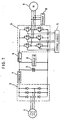
- FIG. 7 illustrates a circuitry structure of a servo amplifier generally known in the art.
- An alternating current from a three-phase alternating-current power supply 1 is converted to a direct current by a semiconductor module 2 constituted by a rectifier circuit such as a diode bridge circuit, and then smoothed by an electrolytic capacitor 3. Subsequently, the direct current is converted into a desired alternating current under PWM control by a semiconductor module 4 and a control circuit 5 which constitute an inverter circuit, so as to drivingly control a servomotor 6.
- a semiconductor module 2 constituted by a rectifier circuit such as a diode bridge circuit
- a general servo amplifier is constituted by parts or components shown in FIG. 7 except the three-phase power supply 1 and the servomotor 6, that is, the semiconductor modules 2 and 4, the control circuit 5, the electrolytic capacitor 3 and the circuits 7 to 10.
- the semiconductor module 2 constituting a rectifier circuit is not accommodated in the same unit case which contains the other parts or components.
- the semiconductor modules 2 and 4 are components which mainly generate beat, although the circuits 7-10 include beat generating parts.
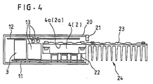
- FIG. 4 is a diagram of the amplifier having the above-described servo amplifier circuitry as viewed from the bottom of the amplifier for showing the internal arrangement thereof
- the aforementioned parts or components constituting the servo amplifier are separately mounted on two printed circuit boards 11 and 12 which are arranged opposite to each other.
- One or both of the semiconductor modules 4 and 2 are mounted on the printed circuit board 11 or 12 so that heat radiating surfaces 4a and 2a thereof are parallel to the printed circuit board 11, 12.
- one or both of the semiconductor modules are mounted on the printed circuit board 11.
- the heat radiating surface 4a, 2a of the semiconductor module 4, 2 has a large area for enhancing heat radiation, but since the heat radiating surface 4a, 2a extends parallel to the printed circuit board 11, 12, size of the heat radiating surface 4a, 2a does not affect width of the servo amplifier, thus permitting reduction in the width of the amplifier.
- a flat heat pipe 23 is attached to the beat radiating surface 4a, 2a of the semiconductor module 4, 2, and a heat sink 24 is attached to a portion of the flat heat pipe 23 which is exposed outside from the rear of a unit case 20. This arrangement permits heat generated by the semiconductor module 4, 2 to be conducted to the heat sink 24 and radiated therefrom away from a region in the unit case 20 where the other components are disposed.
- the heat sink 24 is produced by die casting or the like as a one-piece structure including a flange 21 for mounting the servo amplifier on a locker or a casing of a controller.
- the length of the heat sink 24 in the width direction of the unit case 20 is smaller than the width of the unit case 20. Namely, the heat sink 24 is formed such that the width there of is smaller than the width of the unit case 20.
- the unit case 20 is provided for preventing electric shock, supporting the printed circuit boards 11 and 12, and improving external, appearance, and is securely fixed to the flange 21.
- reference numeral 22 denotes a terminal of the semiconductor module 4, 2.
- the width of the amplifier is restricted by height of tall components among components 13 over than the semiconductor module 2, 4, which is for example a relay or an electrolytic capacitor 3, and other components of small height are mounted in spaces not interfering with such tall components.
- the width of the servo amplifier is determined by the height of the tallest component among the components mounted on the printed circuit boards 11 and 12.
- heat generated by the semiconductor module 4, 2 is radiated from the heat pipe 23 and the beat sink 24, to cool the module 4, 2, but there are some other components of the servo amplifier in the unit case 20 which generate considerable heat and need to be cooled.
- a fan motor is provided in the amplifier to carry out forced air cooling.
- An object of the present invention is to provide a servo amplifier of small thickness.
- a further object of the invention is to provide a downsized and thin servo amplifier capable of efficiently cooling heat generating components therein.
- At least one semiconductor module such as one constituting an inverter essential to a servo amplifier, and first and second printed circuit boards are arranged so that a heat radiating surface of the semiconductor module and surfaces of the printed circuit boards are parallel to inner wall surfaces of a unit case.
- Components mounted on the first and second printed circuit boards have heights substantially equal to or smaller than the thickness of the semiconductor module and also the sum of height of parts positioned in confronting relation with each other on the first and second printed circuit boards is made substantially equal to or smaller than the thickness of the semiconductor module, so that, a distance between the inner walls of the unit case can be made substantially equal to a total thickness of the semiconductor module and the printed circuit board.
- height of components mounted on the printed circuit boards is made substantially equal to or smaller than the sum of the thicknesses of the semiconductor module and the heat sink, and also the distance between the inner walls of the unit case is made substantially equal to the sum of the thicknesses of the semiconductor module, the heat sink and the printed circuit boards.
- guide plates are provided in the unit case to define air passages so that the flow of air produced by fans is forcibly caused to impinge concentratedly on components which need to be cooled, thereby permitting dense arrangement of the components.
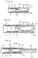
- FIG. 1 shows an internal arrangement of a servo amplifier as viewed from its bottom, according to a first embodiment of the present invention.
- identical reference numerals are used to denote components or elements identical with those of the conventional servo amplifier shown in FIG. 4.
- the first embodiment differs from the conventional servo amplifier shown in FIG. 4 in that the width of the servo amplifier is determined by the thickness of the semiconductor module 4, 2, thereby making the width of the servo amplifier extremely small.
- the component indispensable to the servo amplifier is the semiconductor module 4 constituting an inverter circuit, and the external shape of the semiconductor module 4 places restrictions on the external shape of the servo amplifier. Consequently, the requirement for minimizing the width of the servo amplifier is that the width or distance between inner walls of the unit case 20 of the servo amplifier should not be greater than a width determined by the thickness (width) of the semiconductor module 4.
- the components are arranged in such a manner that those components positioned in confronting relation with each other on the printed circuit boards 11 and 12 do not interfere with each other and also that the sum of the heights of such components is smaller than or equal to the height of the semiconductor module 4, 2. Consequently, the maximum value of thickness of the components contained in the unit case 20 is the sum of thickness of the printed circuit board 11 and the semiconductor module 4, 2. Also, a distance between the inner walls of the unit case 20 is set substantially equal to or slightly greater than the sum of thickness of the printed circuit board 11 and semiconductor module 4, 2, thereby reducing the width and thus the size of the servo amplifier.
- a thin beat sink 25 is attached to the beat radiating surface 4a, 2a of the semiconductor module 4, 2 to radiate heat generated by the module 4, 2.
- the distance between the inner walls of the unit case 20 is substantially equal to the total thickness of the printed circuit board 11, semiconductor module 4, 2 and the heat sink 25.
- forced air cooling described later, may be employed to cool the semiconductor module 4, 2 and other servo amplifier components within the unit case that generate heat and thus need to be cooled.
- FIG. 3 shows an internal arrangement of a servo amplifier as viewed from its bottom, according to a third embodiment of the present invention.
- the third embodiment includes a flat beat pipe 23 and a heat sink 24 which is produced by die casting or the like as a one-piece body having a flange 21 as an integral part thereof, the flat heat pipe 23 being attached to the heat radiating surface 4a, 2a of the semiconductor module 4, 2, while the heat sink 24 being mounted to a portion of the heat pipe 23 extending to the outside from the rear of the unit case 20 so that heat generated by the semiconductor module 4, 2 may be conducted to and dissipated from the heat sink 24.
- the width of the heat sink 24 in the width direction of the unit case 20 is made smaller than the width of the unit case 20 to allow a plurality of unit cases 20 to be placed one upon another.
- the construction described above makes it possible to remarkably improve the efficiency in cooling the semiconductor module 4, 2, compared with the first embodiment shown in FIG. 1 or the second embodiment shown in FIG. 2.
- the third embodiment is almost identical in construction with the first embodiment except that the flat heat pipe 23 and the heat sink 24 are provided, but the distance between the inner walls of the unit case 20 is determined by the total width (total thickness) of the printed circuit board 11, semiconductor module 4, 2 and flat heat pipe 23 and is set to a width slightly greater than the total width (total thickness). Accordingly, components which are to be mounted in regions of the printed circuit boards other than the region in which the semiconductor module 4, 2 is mounted are suitably selected so that their widths (thicknesses) are smaller than the distance between the inner walls of the unit case 20, and also components such as the electrolytic capacitor 3 are divided into a plurality of parts to be arranged at different positions.
- the present invention is directed to a servo amplifier, and therefore, a semiconductor module determines a limit on height (in the present invention, width).
- the servo amplifier is very often expected to handle high voltage and large current and thus the semiconductor module needs to have high withstand voltage and high heat dissipation property, inevitably enlarging the external shape of the semiconductor module.
- transistors are used as part of the circuitry in Japanese Patent Laid-Open Publication No. 8-80040, they can be made flat or be divided and do not place the limit on height.
- the width of a servo amplifier is approximately 50 mm, and there is apparently a large difference.
- the servo amplifier requires various circuits and thus a large number of components, and reduction in the volume of the amplifier makes it necessary to mount the components separately on a plurality of printed circuit boards. Also in this case, there are special restrictions imposed on the servo amplifier, for example, the printed circuit boards need to be arranged so as to face each other, the total height of components positioned in confronting relation with each other on the printed circuit boards should not exceed the height of the semiconductor module.
- a servo amplifier according to another embodiment wherein an improved forced air cooling method is employed to permit reduction of size will be described.
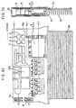
- FIGS. 5a and 5b illustrate air flows observed when a conventional forced air cooling method is applied to the servo amplifier of the third embodiment described above.
- components 13a and 13b besides the semiconductor module 4, 2, are the components that require air cooling.
- air cooling method air is introduced from one side of the unit case 20 and discharged via fans 15 on the other side of the unit case, and in this case, air flows through the entire region of the unit case 20, as indicated by the broken lines in FIG. 5a. Since, in particular, a smaller gap has a greater flow resistance, a larger amount of air tends to flow through a greater gap.
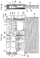
- air passages are defined with the use of arrangement of the components and guide plates 30a, 30b and 30c (hatched in FIGS. 6a and 6b), as shown in FIGS. 6a and 6b, so that a larger amount of air may impinge upon the components 13a and 13b which need to be cooled.
- the guide plate 30a is formed on the unit case 20 or the flange 21 in such an manner as to close gaps between side walls of the unit case 20 and the components, so that air may flow concentratedly to the component 13a requiring cooling as well as to the beat radiating surface of the semiconductor module 4, 2 (surface of the heat pipe 23) to allow a large amount of air to impinge upon these components.
- the guide plates 30b and 30c are arranged in the interior of the unit case 20 in such a manner as to close gaps between the component 13b, which also is arranged inside the unit case and needs to be cooled, and other components, so that air may flow concentratedly to the component 13b to allow a large amount of air to impinge thereupon.
- the width or distance between the inner walls of the unit case 20 is set to a width determined by the total thickness of the printed circuit board 11, semiconductor module 4, 2 and heat pipe 23, and also the air passages are defined with the use of the arrangement of the components and the guide plates so that air may concentratedly impinge upon the components that need to be cooled, whereby the air cooling effect is enhanced and the servo amplifier can be reduced in thickness and thus in size.
- two printed circuit boards 11 and 12 are used by way of example, but a single printed circuit board or three or more subdivided boards may alternatively be used.
- a single printed circuit board or three or more subdivided boards may alternatively be used.
- the present invention is applicable also in cases where a plurality of semiconductor modules are provided.
- the width or distance between the inner walls of the unit case of a servo amplifier is determined by the thickness of a semiconductor module which is indispensable to the servo amplifier, and the other components are arranged so that their heights may be smaller than the above width, whereby the thickness of the servo amplifier can be minimized, making it possible to provide a thin servo amplifier.
- air passages are defined so that air may flow concentratedly to the semiconductor module and other components requiring cooling to forcibly cool them by means of fans, whereby the cooling effect is enhanced, permitting dense arrangement of the components and reduction in size of the servo amplifier.
Landscapes
- Engineering & Computer Science (AREA)
- Microelectronics & Electronic Packaging (AREA)
- Power Engineering (AREA)
- Cooling Or The Like Of Electrical Apparatus (AREA)
- Control Of Electric Motors In General (AREA)
Abstract
Description
Claims (5)
- A servo-amplifier comprising at least one semiconductor module, a first printed circuit board on which the least one semiconductor module is mounted, a second printed circuit board on which at least one semiconductor module is not mounted, and a unit case for accommodating said semiconductor module, said first printed circuit board and said second printed circuit board,
wherein said first printed circuit board and said second printed circuit board are placed opposite to each other, a heat radiating surface of said at least one semiconductor module, said first printed circuit board and said second printed circuit board are arranged parallel to inner wall faces of the unit case, the heights of parts mounted on said first printed circuit board and said second printed circuit board are made equal to or smaller than the thickness of said at least one semiconductor module, the sum of the heights of parts positioned in confronting relation with each other on said first printed circuit board and second printed circuit board is made substantially equal to or smaller than the thickness of said at least one semiconductor module, and the distance between the inner walls of said unit case is made substantially equal to the sum of thickness of said at least one semiconductor module and said first printed circuit board. - A servo-amplifier comprising at least one semiconductor module, a first printed circuit board on which the at least one semiconductor module is mounted, a second printed circuit board on which the at least one semiconductor module is not mounted, a heat sink for cooling said at least one semiconductor module, and a unit case for accommodating said at least one semiconductor module, said first printed circuit board, said second printed circuit board and said heat sink,
wherein said first printed circuit board and said second printed circuit board are placed opposite to each other, a heat radiating surface of said at least one semiconductor module, said first printed circuit board and said second printed circuit board are arranged parallel to inner wall faces of the unit case, said heat sink is attached to the heat radiating surface of said semiconductor module, the heights of parts mounted on said first printed circuit board and said second printed circuit board are made equal to or smaller than the sum of the thickness of said at least one semiconductor module and said heat sink, the sum of the height of parts positioned in confronting relation with each other on said first printed circuit board and second printed circuit board is made substantially equal to or smaller than the sum of the thickness of said at least one semiconductor module and said heat sink, and the distance between the inner walls of said unit case is made substantially equal to the sum of thickness of said at least one semiconductor module, said heat sink and said first printed circuit board. - A servo-amplifier comprising at least one semiconductor module, a first printed circuit board on which the at least one semiconductor module is mounted, a second printed circuit board on which at least one semiconductor module is not mounted, a heat sink with a flat heat pipe for cooling said at least one semiconductor module, and a unit case for accommodating said at least one semiconductor module, said first printed circuit board, said second printed circuit board and said heat sink with the flat heat pipe,
wherein said first printed circuit board and said second printed circuit board are placed opposite to each other, a heat radiating surface of said at least one semiconductor module, said first printed circuit board and said second printed circuit board are arranged parallel to inner wall faces of the unit case, said heat sink with the flat heat pipe is attached to the heat radiating surface of said at least one semiconductor module, the heights of parts mounted on said first printed circuit board and said second printed circuit board are made equal to or smaller than the sum of the thickness of said at least one semiconductor module and said heat sink with the flat heat pipe, the sum of the heights of parts positioned in confronting relation with each other are made substantially equal to or smaller than the sum of the thickness of said at least one semiconductor module and said heat sink with the flat heat pipe, and the distance between the inner walls of said unit case is made substantially equal to the sum of the thickness of said at least one semiconductor module, said heat sink with the flat heat pipe and said first printed circuit board. - A servo-amplifier according to any one of claims 1 to 3, further comprising a cooling fan and a guide plate, wherein a path is formed in said casing for cooling air from the fan in relation to the cooling fan and guide plate so that parts which need cooling are impinged upon by the current of air generated by said cooling fan.
- A servo-amplifier comprising:electronic partsa casing for accommodating said electric parts;a cooling fan; anda guide plate,
wherein a path is formed in said casing for cooling air from the fan in relation to the cooling fan and guide plate so that electronic parts which need cooling are impinged upon by the current of air generated by said cooling fan.
Applications Claiming Priority (2)
| Application Number | Priority Date | Filing Date | Title |
|---|---|---|---|
| JP10121640A JPH11299285A (en) | 1998-04-16 | 1998-04-16 | Servo amplifier |
| JP12164098 | 1998-04-16 |
Publications (3)
| Publication Number | Publication Date |
|---|---|
| EP0951208A2 true EP0951208A2 (en) | 1999-10-20 |
| EP0951208A3 EP0951208A3 (en) | 2000-04-26 |
| EP0951208B1 EP0951208B1 (en) | 2004-11-24 |
Family
ID=14816268
Family Applications (1)
| Application Number | Title | Priority Date | Filing Date |
|---|---|---|---|
| EP99302954A Expired - Lifetime EP0951208B1 (en) | 1998-04-16 | 1999-04-16 | Servo amplifier unit |
Country Status (4)
| Country | Link |
|---|---|
| US (1) | US6292363B1 (en) |
| EP (1) | EP0951208B1 (en) |
| JP (1) | JPH11299285A (en) |
| DE (1) | DE69922078T2 (en) |
Cited By (8)
| Publication number | Priority date | Publication date | Assignee | Title |
|---|---|---|---|---|
| EP1116640A3 (en) * | 2000-01-12 | 2004-11-03 | Omron Corporation | Control unit and method of manufacturing the same |
| EP1793289A1 (en) * | 2005-11-29 | 2007-06-06 | Seiko Epson Corporation | Robot control device and robot system |
| WO2008071192A1 (en) | 2006-12-11 | 2008-06-19 | Danfoss Drives A/S | Electronic device and frequency converter of motor |
| EP2254228A1 (en) * | 2009-05-20 | 2010-11-24 | ABB Schweiz AG | Electronic switching module and system with such switching modules |
| CN102672728A (en) * | 2011-03-08 | 2012-09-19 | 株式会社安川电机 | Robot control device |
| US8363408B2 (en) | 2006-12-11 | 2013-01-29 | Danfoss Drives A/S | Electronic device and frequency converter of motor |
| CN110336515A (en) * | 2018-03-30 | 2019-10-15 | 瀚德万安(上海)电控制动系统有限公司 | Motor control module, actuator and electro-mechanical brake apparatus |
| US10849252B2 (en) | 2018-04-18 | 2020-11-24 | Delta Electronics, Inc. | Converter |
Families Citing this family (16)
| Publication number | Priority date | Publication date | Assignee | Title |
|---|---|---|---|---|
| EP1330866B1 (en) * | 2000-11-03 | 2015-12-30 | SMC Electrical Products, Inc. | Inverter for use in an AC drive |
| AUPR215700A0 (en) * | 2000-12-19 | 2001-01-25 | Fujisawa Pharmaceutical Co., Ltd. | Carboxylic acid compound having cyclopropane ring |
| US6411514B1 (en) * | 2001-03-08 | 2002-06-25 | Rally Manufacturing, Inc. | Power inverter with heat dissipating assembly |
| US7085136B2 (en) * | 2004-04-14 | 2006-08-01 | Thermaltake Technology Ltd. | Heat duct-equipped heat-radiating device for power supply |
| JP4908355B2 (en) * | 2007-09-06 | 2012-04-04 | 株式会社東芝 | Electronic equipment and daughter board |
| US20140118954A1 (en) * | 2011-06-28 | 2014-05-01 | Telefonaktiebolaget L M Ericsson (Publ) | Electronic device with heat-dissipating structure |
| TWM426756U (en) * | 2011-08-04 | 2012-04-11 | Cooler Master Co Ltd | Heat sink with the heat pipe protection mechanism |
| JP5884775B2 (en) | 2013-05-31 | 2016-03-15 | 株式会社豊田自動織機 | Inverter device |
| JP5731610B2 (en) * | 2013-10-15 | 2015-06-10 | ファナック株式会社 | Power supply method for injection molding machine having transformer |
| JP6088464B2 (en) * | 2014-05-29 | 2017-03-01 | ファナック株式会社 | Amplifier integrated robot controller |
| DE102016109078A1 (en) * | 2016-05-18 | 2017-11-23 | Dr. Ing. H.C. F. Porsche Aktiengesellschaft | electronics assembly |
| JP6389211B2 (en) * | 2016-07-15 | 2018-09-12 | 本田技研工業株式会社 | Protective cover for electronic devices |
| CN106602967B (en) * | 2017-01-05 | 2023-11-14 | 四川埃姆克伺服科技有限公司 | Integrated motor drive unit structure |
| JP6434559B2 (en) | 2017-04-10 | 2018-12-05 | ファナック株式会社 | Motor drive device |
| TWI686120B (en) * | 2018-04-18 | 2020-02-21 | 台達電子工業股份有限公司 | Convertor |
| DE112022000713T5 (en) * | 2021-03-18 | 2023-11-09 | Nec Corporation | STRUCTURE OF AN ELECTRONIC DEVICE AND METHOD FOR ASSEMBLY ELECTRONIC DEVICE |
Family Cites Families (16)
| Publication number | Priority date | Publication date | Assignee | Title |
|---|---|---|---|---|
| US4177499A (en) | 1977-11-14 | 1979-12-04 | Volkmann Electric Drives Corporation | Electronic assembly with heat sink means |
| JPS6413751A (en) * | 1987-07-08 | 1989-01-18 | Seiko Epson Corp | Semiconductor circuit unit for power supply |
| JP2624784B2 (en) * | 1988-06-29 | 1997-06-25 | 株式会社日立製作所 | Inverter device |
| KR920005988B1 (en) | 1988-08-31 | 1992-07-25 | 가부시기가이샤 히다찌세이사꾸쇼 | Inverter |
| JP2570861B2 (en) * | 1989-02-10 | 1997-01-16 | 富士電機株式会社 | Inverter device |
| JP2626326B2 (en) * | 1991-07-31 | 1997-07-02 | 三菱電機株式会社 | Motor control unit |
| US5297025A (en) * | 1992-10-28 | 1994-03-22 | Onan Corporation | Power supply assembly |
| JPH077994A (en) | 1993-06-17 | 1995-01-10 | Matsushita Electric Ind Co Ltd | Servo motor drive controller |
| JPH0739167A (en) | 1993-07-23 | 1995-02-07 | Fuji Electric Co Ltd | Inverter device and inverter device installation device |
| EP0655881A1 (en) | 1993-11-26 | 1995-05-31 | Siemens Aktiengesellschaft | Casing |
| JPH07222458A (en) * | 1994-01-28 | 1995-08-18 | Sharp Corp | Grid-connected inverter |
| JPH07297561A (en) | 1994-04-21 | 1995-11-10 | Mitsubishi Electric Corp | Electronic device housing |
| JP3348552B2 (en) | 1994-12-28 | 2002-11-20 | 富士電機株式会社 | Electronic equipment cooling device |
| JPH08289566A (en) | 1995-04-18 | 1996-11-01 | Toshiba Corp | Motor drive |
| JPH0928094A (en) | 1995-07-12 | 1997-01-28 | Matsushita Electric Ind Co Ltd | Servo controller |
| JPH11148977A (en) | 1997-11-13 | 1999-06-02 | Yoshihiko Akao | Approximate estimation method for attenuation of earthquake wave with respect to distance |
-
1998
- 1998-04-16 JP JP10121640A patent/JPH11299285A/en active Pending
-
1999
- 1999-04-16 DE DE69922078T patent/DE69922078T2/en not_active Expired - Fee Related
- 1999-04-16 US US09/292,920 patent/US6292363B1/en not_active Expired - Fee Related
- 1999-04-16 EP EP99302954A patent/EP0951208B1/en not_active Expired - Lifetime
Cited By (18)
| Publication number | Priority date | Publication date | Assignee | Title |
|---|---|---|---|---|
| EP1116640A3 (en) * | 2000-01-12 | 2004-11-03 | Omron Corporation | Control unit and method of manufacturing the same |
| CN102626927A (en) * | 2005-11-29 | 2012-08-08 | 精工爱普生株式会社 | Robot control device and robot system |
| CN101879719B (en) * | 2005-11-29 | 2016-02-17 | 精工爱普生株式会社 | Robot controller and robot system |
| US7769489B2 (en) | 2005-11-29 | 2010-08-03 | Seiko Epson Corporation | Robot control device and robot system |
| CN101879719A (en) * | 2005-11-29 | 2010-11-10 | 精工爱普生株式会社 | Robot controller and robot system |
| US8599555B2 (en) | 2005-11-29 | 2013-12-03 | Seiko Epson Corporation | Robot control device and robot system |
| CN102626928A (en) * | 2005-11-29 | 2012-08-08 | 精工爱普生株式会社 | Robot control device and robot system |
| CN102626926A (en) * | 2005-11-29 | 2012-08-08 | 精工爱普生株式会社 | Robot control device and robot system |
| EP1793289A1 (en) * | 2005-11-29 | 2007-06-06 | Seiko Epson Corporation | Robot control device and robot system |
| WO2008071192A1 (en) | 2006-12-11 | 2008-06-19 | Danfoss Drives A/S | Electronic device and frequency converter of motor |
| US8310830B2 (en) | 2006-12-11 | 2012-11-13 | Danfoss Drives A/S | Electronic device and frequency converter of motor |
| US8363408B2 (en) | 2006-12-11 | 2013-01-29 | Danfoss Drives A/S | Electronic device and frequency converter of motor |
| EP2254228A1 (en) * | 2009-05-20 | 2010-11-24 | ABB Schweiz AG | Electronic switching module and system with such switching modules |
| CN102672728A (en) * | 2011-03-08 | 2012-09-19 | 株式会社安川电机 | Robot control device |
| CN102672728B (en) * | 2011-03-08 | 2015-12-16 | 株式会社安川电机 | Robot controller |
| CN110336515A (en) * | 2018-03-30 | 2019-10-15 | 瀚德万安(上海)电控制动系统有限公司 | Motor control module, actuator and electro-mechanical brake apparatus |
| CN110336515B (en) * | 2018-03-30 | 2021-12-28 | 瀚德万安(上海)电控制动系统有限公司 | Motor control module, actuator and electromechanical brake device |
| US10849252B2 (en) | 2018-04-18 | 2020-11-24 | Delta Electronics, Inc. | Converter |
Also Published As
| Publication number | Publication date |
|---|---|
| JPH11299285A (en) | 1999-10-29 |
| DE69922078T2 (en) | 2005-04-07 |
| DE69922078D1 (en) | 2004-12-30 |
| EP0951208B1 (en) | 2004-11-24 |
| EP0951208A3 (en) | 2000-04-26 |
| US6292363B1 (en) | 2001-09-18 |
Similar Documents
| Publication | Publication Date | Title |
|---|---|---|
| EP0951208B1 (en) | Servo amplifier unit | |
| EP2089962B1 (en) | Electronic device and frequency converter of motor | |
| US20030030980A1 (en) | Electronics cooling subassembly | |
| US20150348694A1 (en) | Cooling structure for magnetic component and power converter provided therewith | |
| KR20160129696A (en) | Cooling case for electronic device, electronic device, and construction machine | |
| TWI661656B (en) | Motor drive | |
| JPH1169774A (en) | Power converter | |
| US9960654B2 (en) | Dual air and liquid cooling media compatible electric machine electronics | |
| EP4075934A1 (en) | Packaging of power conversion unit | |
| EP1767307A1 (en) | Arc welding control device | |
| JP5716598B2 (en) | Power supply | |
| JP4744237B2 (en) | Circuit board cooling mechanism | |
| US20200120837A1 (en) | Fluid cooled power electronic assembly | |
| JPH1026372A (en) | Outdoor unit of air conditioner | |
| US10098256B2 (en) | Electronic device | |
| JPH07249885A (en) | Cooling structure | |
| US6719038B2 (en) | Heat removal system | |
| EP4350969B1 (en) | Bus bar heat dissipation structure and inverter device | |
| JPH05260763A (en) | Sheet metal construction for inverter apparatus | |
| JP5046087B2 (en) | Motor control device | |
| CN114224509A (en) | Main unit connected with surgical instrument and surgical equipment | |
| JP5716599B2 (en) | Power supply | |
| JPH09322334A (en) | control panel | |
| JP5609811B2 (en) | Power supply | |
| JP7464183B1 (en) | Power Conversion Equipment |
Legal Events
| Date | Code | Title | Description |
|---|---|---|---|
| PUAI | Public reference made under article 153(3) epc to a published international application that has entered the european phase |
Free format text: ORIGINAL CODE: 0009012 |
|
| AK | Designated contracting states |
Kind code of ref document: A2 Designated state(s): DE |
|
| AX | Request for extension of the european patent |
Free format text: AL;LT;LV;MK;RO;SI |
|
| PUAL | Search report despatched |
Free format text: ORIGINAL CODE: 0009013 |
|
| AK | Designated contracting states |
Kind code of ref document: A3 Designated state(s): AT BE CH CY DE DK ES FI FR GB GR IE IT LI LU MC NL PT SE |
|
| AX | Request for extension of the european patent |
Free format text: AL;LT;LV;MK;RO;SI |
|
| RIC1 | Information provided on ipc code assigned before grant |
Free format text: 7H 05K 7/14 A, 7H 02M 7/00 B, 7H 05K 7/20 B |
|
| 17P | Request for examination filed |
Effective date: 20000906 |
|
| AKX | Designation fees paid |
Free format text: DE |
|
| 17Q | First examination report despatched |
Effective date: 20030507 |
|
| GRAP | Despatch of communication of intention to grant a patent |
Free format text: ORIGINAL CODE: EPIDOSNIGR1 |
|
| GRAS | Grant fee paid |
Free format text: ORIGINAL CODE: EPIDOSNIGR3 |
|
| GRAA | (expected) grant |
Free format text: ORIGINAL CODE: 0009210 |
|
| AK | Designated contracting states |
Kind code of ref document: B1 Designated state(s): DE |
|
| REF | Corresponds to: |
Ref document number: 69922078 Country of ref document: DE Date of ref document: 20041230 Kind code of ref document: P |
|
| PLBE | No opposition filed within time limit |
Free format text: ORIGINAL CODE: 0009261 |
|
| STAA | Information on the status of an ep patent application or granted ep patent |
Free format text: STATUS: NO OPPOSITION FILED WITHIN TIME LIMIT |
|
| 26N | No opposition filed |
Effective date: 20050825 |
|
| PGFP | Annual fee paid to national office [announced via postgrant information from national office to epo] |
Ref country code: DE Payment date: 20080424 Year of fee payment: 10 |
|
| PG25 | Lapsed in a contracting state [announced via postgrant information from national office to epo] |
Ref country code: DE Free format text: LAPSE BECAUSE OF NON-PAYMENT OF DUE FEES Effective date: 20091103 |