EP0951149A2 - Konfigurierbares Nachrichtenübertragungsgerät das den Gebrauch nicht verwendeter Multiplexerkanäle während eines hohen Verbrauchsmodus erlaubt - Google Patents
Konfigurierbares Nachrichtenübertragungsgerät das den Gebrauch nicht verwendeter Multiplexerkanäle während eines hohen Verbrauchsmodus erlaubt Download PDFInfo
- Publication number
- EP0951149A2 EP0951149A2 EP99302813A EP99302813A EP0951149A2 EP 0951149 A2 EP0951149 A2 EP 0951149A2 EP 99302813 A EP99302813 A EP 99302813A EP 99302813 A EP99302813 A EP 99302813A EP 0951149 A2 EP0951149 A2 EP 0951149A2
- Authority
- EP
- European Patent Office
- Prior art keywords
- amplifier
- channels
- communication channel
- switches
- output
- Prior art date
- Legal status (The legal status is an assumption and is not a legal conclusion. Google has not performed a legal analysis and makes no representation as to the accuracy of the status listed.)
- Withdrawn
Links
- 238000004891 communication Methods 0.000 title claims abstract description 107
- 230000008878 coupling Effects 0.000 claims description 6
- 238000010168 coupling process Methods 0.000 claims description 6
- 238000005859 coupling reaction Methods 0.000 claims description 6
- 238000012986 modification Methods 0.000 description 4
- 230000004048 modification Effects 0.000 description 4
- 230000005540 biological transmission Effects 0.000 description 1
- 238000010276 construction Methods 0.000 description 1
Images

Classifications
-
- H—ELECTRICITY
- H03—ELECTRONIC CIRCUITRY
- H03F—AMPLIFIERS
- H03F3/00—Amplifiers with only discharge tubes or only semiconductor devices as amplifying elements
- H03F3/54—Amplifiers using transit-time effect in tubes or semiconductor devices
- H03F3/58—Amplifiers using transit-time effect in tubes or semiconductor devices using travelling-wave tubes
-
- H—ELECTRICITY
- H04—ELECTRIC COMMUNICATION TECHNIQUE
- H04B—TRANSMISSION
- H04B1/00—Details of transmission systems, not covered by a single one of groups H04B3/00 - H04B13/00; Details of transmission systems not characterised by the medium used for transmission
- H04B1/74—Details of transmission systems, not covered by a single one of groups H04B3/00 - H04B13/00; Details of transmission systems not characterised by the medium used for transmission for increasing reliability, e.g. using redundant or spare channels or apparatus
Definitions
- the present invention relates generally to communication apparatus, for example for use as spacecraft communication apparatus. Particularly, but not exclusively, the invention relates to amplifier redundancy ring communication apparatus that can be configured to use normally unused multiplexer channels when operating in high power mode.
- the assignee of the present invention manufactures and deploys communication satellites that carry communication systems as their payloads.
- a typical communication system uses two or more separate and independent amplifier channels that each form a redundancy ring.
- a plurality of single input, multiple output, input multiplexers that are coupled to a multiple input, single output, output multiplexer by means of a set of amplifier channels that form the redundancy ring.
- Each redundancy ring contains a plurality of amplified communication paths (amplifier channels) that route signals from the outputs of the input multiplexers to the inputs of the output multiplexer.
- each independent set of amplifier channels forming the redundancy ring extra amplifier channels are provided that may be used in case of failure of one of the other amplifier channels within that redundancy ring. If an amplifier channel fails, one of the extra amplifier channels is switched into the circuit to replace it.
- the amplified communication paths each contain a travelling wave tube amplifier (TWTA), for example. Pairs of travelling wave tube amplifiers may be selectively coupled together to provide for high power operation. Thus, the travelling wave tube amplifiers may be controlled to operate in (1) a single travelling wave tube (TWT) mode and in (2) a high power combined travelling wave tube (TWT) mode using a coupled pair of travelling wave tube amplifiers.
- TWTA travelling wave tube amplifier
- TWT travelling wave tube amplifier
- TWT travelling wave tube amplifier
- communication apparatus comprising:
- communication apparatus comprising:
- the communication apparatus thus comprises a plurality of multiple output, input multiplexers and a plurality of multiple input, output multiplexers. Outputs of the input multiplexers are coupled to inputs of the output multiplexers by way of a plurality of amplifier channels. A plurality of redundant amplifier channels are provided that complete the redundancy ring. Each redundancy ring contains a plurality of amplified communication paths (amplifier channels) that route signals from the outputs of the input multiplexers to the inputs of the output multiplexer along with additional amplifier channels that may be used in case of failure of one of the amplifier channels.
- amplified communication paths amplifier channels
- the present invention provides communication apparatus that is selectively configurable to provide for the use of normally unused output multiplexer channels when it is operated in high power mode.
- the apparatus uses selectively interconnected amplifier channels of its redundancy rings to permit normally unused output multiplexer channels to be used when the system is configured to operate in high power mode.
- pairs of amplifier channels may be selectively coupled together.
- the amplifier channels may be configured to operate in a single amplifier mode wherein each amplifier channel operates independently, and in a high power combined amplifier mode wherein both amplifier channels of a pair are coupled together to provide high power output.
- switching circuitry is provided that (1) permits the extra amplifier channels to be switched into the circuit if other amplifier channels fail, as is the case with the prior system, but (2) also provides the capability to switch an unused amplifier channel into the circuit to provide a communication channel between the corresponding output and input of the input and output multiplexers that is normally provided by the "coupled" amplifier channel.
- the unused amplifier channel that is switched into the circuit is typically the corresponding amplifier channel of the other redundancy ring. However, this need not be the case, in that any of the unused amplifier channels may be switched into the circuit to provide the communication path.
- the present invention thus provides the capability to use previously unused multiplexer channels by switching in a single amplifier or combined pair of travelling wave tube amplifiers from a different TWT redundancy ring.
- the aspect of the present invention provides added flexibility for customers and a simplicity in the design that "backfills" the unused multiplexer channels.
- outputs of the input multiplexers of each redundancy ring are interconnected together by means of controllable switches.
- inputs of the output multiplexers of each redundancy ring are interconnected together by means of controllable switches.
- the switches are controlled by means of a controller that selectively activates the switches to interconnect a particular input multiplexer output to the appropriate output multiplexer input, thus providing a communication path therebetween.
- the arrangement of switches permits controlled selection of the alternative path through any of the unused amplifier channels.
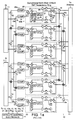
- Figs. 1a and 1b illustrate communication apparatus 10 comprising conventional separate travelling wave tube amplifier (TWTA) redundancy rings 10 used in spacecraft communication systems previously deployed by the assignee of the present invention. More specifically, Figs. 1a and 1b illustrate two conventional and separate 12-for-8 TWTA redundancy rings 10 used to amplify input signals that are supplied to transmit antennas (not shown) for transmission.
- the redundancy rings 10 are identified as a North-West redundancy ring 10 (Fig. 1a) and a South-West redundancy ring 10 (Fig. 1b).
- Each redundancy ring 10 comprises a plurality of amplified communication paths 20a or amplifier channels 20a.
- the communication apparatus 10 shown in Fig. 1a is substantially the same as that shown in Fig. 1b, so a description of Fig. 1a will be provided that describes both circuits.
- Input signals are applied to inputs of a plurality of single input, multiple output input multiplexers 11 (or to an input of a single input multiplexer 11) which output a plurality of separate output signals at individual outputs of the input multiplexers 11 (corresponding to a plurality of communication paths 20a).
- Each of the outputs of the input multiplexers 11 are coupled by way of a controllable input switch 12, 12a to a channel amplifier (CAMP) 14.
- CAMP channel amplifier
- Outputs of the channel amplifiers 14 are routed through individual amplifier channels 20a of the redundancy ring 10 and are coupled by way of controllable output switches 16, 16a to inputs of a multiple input, single output, output multiplexer 15.
- the output of the output multiplexer 15 is coupled to the transmit antenna (not shown).
- Each redundancy ring 10 comprises a plurality of amplified communication paths 20a (amplifier channels 20a) that amplify signals derived from the outputs of the input multiplexers 11 that are coupled to the inputs of the output multiplexer 15.
- Each of the amplifier channels 20a comprise a travelling wave tube amplifier 26, along with controllable switches 21, 28, input and output hybrid (H) couplers 23, phase shifters ( ⁇ ) 22, 24, and terminated circulators 27, constructed substantially as shown.
- a electrical power conditioner (EPC) 25 comprising a high voltage power supply, is coupled to selected pairs of travelling wave tube amplifiers 26.
- the channel amplifiers 14 are used to set the gain of the signal supplied to the travelling wave tube amplifier 26 disposed in the respective communication path 20a.
- a plurality of controllable input redundancy switches 13 are coupled between selected controllable input switches 12, 12a and corresponding channel amplifiers 14 of the redundant amplifier channels 20a.
- a plurality of controllable output redundancy switches 17 are selectively coupled between outputs of the redundant amplifier channels 20a and selected controllable output switches 16, 16a.
- Satellite control electronics 18 is provided that operates as a controller and has control lines that are coupled to each of the switches 12, 12a, 13, 16, 16a, 17, 21, 28 and that are used to selectively control or toggle the switches 12, 12a, 13, 16, 16a, 17, 21, 28 to route selected signals through the plurality of amplifier channels 20a.
- each redundancy ring 10 contains extra amplifier channels 20a that may be used in case of failure of another of the amplifier channels 20a in that ring 10.
- one of the extra amplifier channels 20a may be switched into the circuit to replace it.
- the satellite control electronics 18 is used to toggle the switches 12, 12a, 13, 16, 16a, 17, 21, 28 to switch the extra amplifier channels 20a into the circuit.
- Pairs of travelling wave tube amplifiers 26 may be selectively coupled together to provide for high power operation.
- the electrical power conditioner supplies high voltage to the travelling wave tube amplifiers 26.
- the switch controller 18 selectively switches the input and output switches 12, 12a, 16, 16a to remove the undesired amplifier channel 20a from its normal communication path and couples the output of the amplifiers 26 by way of the switches 21, 28 and hybrid couplers 23 to the other communication path which is combined to produce the high power output.
- channel 1 when channel 1, for example, is selected for high power mode, the output of the TWT amplifier 26 normally used to support traffic for channel 2 is switched into the output hybrid coupler 23 to provide for high power combining.
- This provides high output power for channel 1, but leaves channel 2 in the input and output multiplexers 11, 15 unused.
- the travelling wave tube amplifiers 26 may be controlled to operate in a normal (low power) mode or in a high power combined mode using coupled travelling wave tube amplifiers 26.
- the conventional system 10 is configured to operate in the normal (low power) mode, the outputs of the input multiplexers 11 are routed straight through to the inputs of the output multiplexer 15, and all communication paths 20a are used.
- the conventional system is configured to operate in the high power mode, the communication path for the channel of the "coupled" amplifier 26 is not used. Consequently, all communication paths 20a are not used when the conventional system 10 is operated in the high power mode.
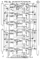
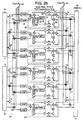
- FIGs. 2a and 2b they illustrate improved communication apparatus 30 in accordance with the principles of the present invention.
- the construction of the apparatus 30 shown in Figs. 2a and 2b is generally the same as that of Figs. 1a and 1b, but with certain modifications and will be discussed below.
- the present apparatus 30 overcomes limitations of the prior apparatus 10 by providing switching circuitry and interconnection paths between amplifier channels 20a of each of the redundancy rings 10.
- the communication apparatus 30 employs switchably interconnected amplifier channels 20a of separate redundancy rings 10 that permit use of normally unused multiplexer channels when the amplifiers 26 are operated in high power mode.
- the communication apparatus 30 comprises a plurality of multiple output, input multiplexers 11 and a plurality of multiple input, output multiplexers 15. Outputs of the input multiplexers 11 are coupled to inputs of the output multiplexers 15 by way of a plurality of amplifier channels 20a. A plurality of redundant amplifier channels 20a are provided that complete the redundancy ring 10. Each redundancy ring 10 has a plurality of amplified communication paths 20a (amplifier channels 20a) that route signals from the outputs of input multiplexers 11 to inputs of an output multiplexer 15 along with additional amplifier channels 20a that may be used in case of failure of one of the amplifier channels 20a.
- amplified communication paths 20a amplifier channels 20a
- outputs of the input multiplexers 11 of each redundancy ring 10 are interconnected together by means of selectively interconnected and controllable switches 12, 13, 13a.
- inputs of the output multiplexers 15 of each redundancy ring 10 are interconnected together by means of selectively interconnected and controllable switches 16, 17, 17a.
- Certain of the switches 13a operate to couple signals between the redundancy rings 10.
- the switches 12, 13, 13a 16, 17, 17a are controlled by means of spacecraft control electronics 18 (or controller 18) that selectively activates the switches 12, 13, 13a, 16, 17, 17a to interconnect a particular output of an input multiplexer 11 to the appropriate input of an output multiplexer 15, thus providing a communication path therebetween.
- the arrangement of switches 12, 13, 13a, 16, 17, 17a permits controlled selection of alternative paths through any of the unused amplifier channels 20a.
- Pairs of amplifier channels 20a may be selectively coupled together.
- the amplifier channels 20a may be configured to operate in a normal amplifier mode wherein each amplifier channel 20a operates independently, and in a high power combined amplifier mode wherein both amplifier channels 20a of a pair are coupled together to provide high power output. This is implemented in the manner discussed with reference to Figs. 1a and 1b.
- modified switching circuitry is provided that (1) permit the extra amplifier channels 20a to be switched into the circuit if other amplifier channels 20a fail, as is the case with the prior system, and (2) also provides the capability to switch an unused amplifier channel 20a into the circuit to provide a communication channel between the corresponding output and input of the input and output multiplexers 11, 15 that is normally provided by the "coupled" amplifier channel 20a.
- the unused amplifier channel 20a that is switched into the circuit is typically the corresponding amplifier channel 20a of the other redundancy ring 10. However, this need not be the case, in that any of the unused amplifier channels 20a may be switched into the circuit to provide the communication path. Selection of the appropriate amplifier channel 20a is typically a function of design choice, taking into account the power availability, loading, and traffic demand.
- the present invention thus provides the capability to use previously unused multiplexer channels by switching in a single amplifier channel 20a or combined pair of travelling wave tube amplifiers, such as from a different TWT redundancy ring 10, for example.
- the aspect of the present invention provides added flexibility and a simplicity in the design that "backfills" the unused multiplexer channels.
- the switching circuitry permits extra amplifier channels 20a to be switched into the circuit if other amplifier channels 20a fail, and provides the capability to switch an unused amplifier channel into the circuit to provide a communication channel between the corresponding output and input of the input and output multiplexers 11, 15 that is normally provided by the "coupled" amplifier channel 20a when operating in high power mode.
- the unused amplifier channel 20a that is switched into the circuit is typically the corresponding amplifier channel of the other redundancy ring 10. However, this need not be the case, in that any of the unused amplifier channels 20a may be switched into the circuit to provide the communication path, subject to power, loading, and traffic demand.
- TWT amplifiers 26 from one redundancy ring 10 can be used to "backfill" the unused channels 20a in the output multiplexer 15 coupled to the other redundancy ring 10.
- This configuration adds flexibility that allows configuration of the TWT amplifiers on board a spacecraft and also maintain a 12-for-8 TWT redundancy, for example, in both TWT redundancy rings 10.
Landscapes
- Engineering & Computer Science (AREA)
- Power Engineering (AREA)
- Computer Networks & Wireless Communication (AREA)
- Signal Processing (AREA)
- Radio Relay Systems (AREA)
- Amplifiers (AREA)
- Transmitters (AREA)
- Microwave Amplifiers (AREA)
Applications Claiming Priority (2)
| Application Number | Priority Date | Filing Date | Title |
|---|---|---|---|
| US62548 | 1998-04-18 | ||
| US09/062,548 US6301225B1 (en) | 1998-04-18 | 1998-04-18 | Configurable communication apparatus that permits use of unused multiplexer channels when operating in high power mode |
Publications (2)
| Publication Number | Publication Date |
|---|---|
| EP0951149A2 true EP0951149A2 (de) | 1999-10-20 |
| EP0951149A3 EP0951149A3 (de) | 2001-10-04 |
Family
ID=22043220
Family Applications (1)
| Application Number | Title | Priority Date | Filing Date |
|---|---|---|---|
| EP99302813A Withdrawn EP0951149A3 (de) | 1998-04-18 | 1999-04-12 | Konfigurierbares Nachrichtenübertragungsgerät das den Gebrauch nicht verwendeter Multiplexerkanäle während eines hohen Verbrauchsmodus erlaubt |
Country Status (3)
| Country | Link |
|---|---|
| US (1) | US6301225B1 (de) |
| EP (1) | EP0951149A3 (de) |
| JP (1) | JPH11308124A (de) |
Cited By (5)
| Publication number | Priority date | Publication date | Assignee | Title |
|---|---|---|---|---|
| EP1148636A3 (de) * | 2000-04-07 | 2005-10-26 | Harris Corporation | Hochfrequenzleistungsverstärker mit verteilter Kodierung der Modulation |
| FR2921216A1 (fr) * | 2007-09-17 | 2009-03-20 | Astrium Sas Soc Par Actions Si | Dispositif de traitement de signaux radiofrequences, procede d'evacuation d'energie radiofrequence dans un tel o dispositif, engin aerien ou spatial comprenant un tel dispositif |
| US8208874B2 (en) | 2006-05-05 | 2012-06-26 | Astrium Limited | RF power amplifiers |
| EP3297174A1 (de) * | 2016-09-16 | 2018-03-21 | Space Systems/Loral, LLC | Netzzugangsnetzwerk mit redundanz |
| CN108683446A (zh) * | 2018-03-29 | 2018-10-19 | 西安空间无线电技术研究所 | 一种通信卫星转发器双频带功放备份环及切换方法 |
Families Citing this family (5)
| Publication number | Priority date | Publication date | Assignee | Title |
|---|---|---|---|---|
| US7369810B2 (en) * | 2001-10-05 | 2008-05-06 | The Boeing Company | Satellite transponder architecture with integral redundancy and beam selection capabilities |
| US7443789B2 (en) * | 2001-11-21 | 2008-10-28 | Adc Dsl Systems, Inc. | Protection switching mechanism |
| US9786361B1 (en) | 2015-07-31 | 2017-10-10 | Flex Logix Technologies, Inc. | Programmable decoupling capacitance of configurable logic circuitry and method of operating same |
| US10382320B2 (en) * | 2016-10-07 | 2019-08-13 | The Boeing Company | Cascaded redundancy architectures for communication systems |
| JP6734209B2 (ja) * | 2017-02-13 | 2020-08-05 | 日本電信電話株式会社 | 電力増幅装置および電力増幅制御方法 |
Family Cites Families (3)
| Publication number | Priority date | Publication date | Assignee | Title |
|---|---|---|---|---|
| US5649310A (en) * | 1994-06-15 | 1997-07-15 | Space Systems/Loral, Inc. | Signal translation and amplification system including a thermal radiation panel coupled thereto |
| GB2314725B (en) * | 1996-06-28 | 2000-03-08 | Matra Marconi Space Uk Ltd | Switching means for use on-board a spacecraft |
| US5978652A (en) * | 1997-01-10 | 1999-11-02 | Space Systems/Loral, Inc. | Common direct broadcasting service system |
-
1998
- 1998-04-18 US US09/062,548 patent/US6301225B1/en not_active Expired - Fee Related
- 1998-11-18 JP JP10327684A patent/JPH11308124A/ja active Pending
-
1999
- 1999-04-12 EP EP99302813A patent/EP0951149A3/de not_active Withdrawn
Cited By (7)
| Publication number | Priority date | Publication date | Assignee | Title |
|---|---|---|---|---|
| EP1148636A3 (de) * | 2000-04-07 | 2005-10-26 | Harris Corporation | Hochfrequenzleistungsverstärker mit verteilter Kodierung der Modulation |
| US8208874B2 (en) | 2006-05-05 | 2012-06-26 | Astrium Limited | RF power amplifiers |
| FR2921216A1 (fr) * | 2007-09-17 | 2009-03-20 | Astrium Sas Soc Par Actions Si | Dispositif de traitement de signaux radiofrequences, procede d'evacuation d'energie radiofrequence dans un tel o dispositif, engin aerien ou spatial comprenant un tel dispositif |
| EP3297174A1 (de) * | 2016-09-16 | 2018-03-21 | Space Systems/Loral, LLC | Netzzugangsnetzwerk mit redundanz |
| US10284283B2 (en) | 2016-09-16 | 2019-05-07 | Space Systems/Loral, Llc | Access switch network with redundancy |
| CN108683446A (zh) * | 2018-03-29 | 2018-10-19 | 西安空间无线电技术研究所 | 一种通信卫星转发器双频带功放备份环及切换方法 |
| CN108683446B (zh) * | 2018-03-29 | 2021-04-13 | 西安空间无线电技术研究所 | 一种通信卫星转发器双频带功放备份环及切换方法 |
Also Published As
| Publication number | Publication date |
|---|---|
| JPH11308124A (ja) | 1999-11-05 |
| US6301225B1 (en) | 2001-10-09 |
| EP0951149A3 (de) | 2001-10-04 |
Similar Documents
| Publication | Publication Date | Title |
|---|---|---|
| US4070637A (en) | Redundant microwave configuration | |
| CA1236178A (en) | Power amplifying apparatus | |
| US9564865B2 (en) | Redundant amplifier and switching method thereof | |
| US6023359A (en) | Optical wavelength-division multiplex transmission equipment with a ring structure | |
| US6301225B1 (en) | Configurable communication apparatus that permits use of unused multiplexer channels when operating in high power mode | |
| JP5398957B2 (ja) | 電力増幅器システム | |
| US5610556A (en) | Multi-port amplifiers with switchless redundancy | |
| WO2003015212A1 (en) | Partially deployed active phased array antenna system | |
| GB2322494A (en) | Spacecraft with parallel amplifiers and redundancy | |
| EP0396015A1 (de) | Transponder mit Antennenstrahlauswahl und gemeinsamer Benutzung von Antennen- und Zuführungselementen | |
| US5033108A (en) | Signal repeater using shared amplification with selectable input/output connections | |
| WO2008125876A1 (en) | Routing of downlink channels in a communications satellite | |
| JP2020502935A (ja) | マルチモードアクティブ電子走査アレイのためのシステム及び方法 | |
| US7369810B2 (en) | Satellite transponder architecture with integral redundancy and beam selection capabilities | |
| US6020796A (en) | Switching means for use on-board a spacecraft | |
| JP2003218762A (ja) | 衛星用ダウンリンク切換機構 | |
| US6943625B2 (en) | Gain and phase balanced amplifier redundancy system | |
| EP0908964B1 (de) | Kompakte Redundanz-Kombiniereinrichtung und Verfahren zu deren Betrieb | |
| US20150256128A1 (en) | Multi-port amplifier and method for controlling thereof | |
| US6295282B1 (en) | Calibrated low loss radio frequency switch matrix | |
| JPH10303662A (ja) | 故障の場合でも劣化が少ない電力増幅器装置 | |
| EP1328075A2 (de) | Redundante Schaltung einer Nutzlast für einen Satelliten | |
| EP3297174B1 (de) | Netzzugangsnetzwerk mit redundanz | |
| JPS60165874A (ja) | 分岐分配増幅器 | |
| Kuroda et al. | 3-5 Ka-band High Power Multi-port Amplifier (MPA) |
Legal Events
| Date | Code | Title | Description |
|---|---|---|---|
| PUAI | Public reference made under article 153(3) epc to a published international application that has entered the european phase |
Free format text: ORIGINAL CODE: 0009012 |
|
| AK | Designated contracting states |
Kind code of ref document: A2 Designated state(s): AT BE CH CY DE DK ES FI FR GB GR IE IT LI LU MC NL PT SE Kind code of ref document: A2 Designated state(s): DE FR GB IT |
|
| AX | Request for extension of the european patent |
Free format text: AL;LT;LV;MK;RO;SI |
|
| RAP3 | Party data changed (applicant data changed or rights of an application transferred) |
Owner name: SPACE SYSTEMS / LORAL, INC. |
|
| PUAL | Search report despatched |
Free format text: ORIGINAL CODE: 0009013 |
|
| AK | Designated contracting states |
Kind code of ref document: A3 Designated state(s): AT BE CH CY DE DK ES FI FR GB GR IE IT LI LU MC NL PT SE |
|
| AX | Request for extension of the european patent |
Free format text: AL;LT;LV;MK;RO;SI |
|
| RIC1 | Information provided on ipc code assigned before grant |
Free format text: 7H 04B 1/74 A, 7H 04B 7/185 B |
|
| 17P | Request for examination filed |
Effective date: 20020117 |
|
| R17P | Request for examination filed (corrected) |
Effective date: 20011121 |
|
| AKX | Designation fees paid |
Free format text: DE FR GB IT |
|
| 17Q | First examination report despatched |
Effective date: 20020813 |
|
| GRAH | Despatch of communication of intention to grant a patent |
Free format text: ORIGINAL CODE: EPIDOS IGRA |
|
| STAA | Information on the status of an ep patent application or granted ep patent |
Free format text: STATUS: THE APPLICATION HAS BEEN WITHDRAWN |
|
| 18W | Application withdrawn |
Effective date: 20030710 |