EP0951101A2 - A connector - Google Patents
A connector Download PDFInfo
- Publication number
- EP0951101A2 EP0951101A2 EP99106225A EP99106225A EP0951101A2 EP 0951101 A2 EP0951101 A2 EP 0951101A2 EP 99106225 A EP99106225 A EP 99106225A EP 99106225 A EP99106225 A EP 99106225A EP 0951101 A2 EP0951101 A2 EP 0951101A2
- Authority
- EP
- European Patent Office
- Prior art keywords
- housing
- lock arm
- connector according
- receptacle
- electric part
- Prior art date
- Legal status (The legal status is an assumption and is not a legal conclusion. Google has not performed a legal analysis and makes no representation as to the accuracy of the status listed.)
- Granted
Links
Images


Classifications
-
- H—ELECTRICITY
- H01—ELECTRIC ELEMENTS
- H01R—ELECTRICALLY-CONDUCTIVE CONNECTIONS; STRUCTURAL ASSOCIATIONS OF A PLURALITY OF MUTUALLY-INSULATED ELECTRICAL CONNECTING ELEMENTS; COUPLING DEVICES; CURRENT COLLECTORS
- H01R13/00—Details of coupling devices of the kinds covered by groups H01R12/70 or H01R24/00 - H01R33/00
- H01R13/62—Means for facilitating engagement or disengagement of coupling parts or for holding them in engagement
- H01R13/627—Snap or like fastening
- H01R13/6271—Latching means integral with the housing
- H01R13/6273—Latching means integral with the housing comprising two latching arms
Definitions
- the present invention relates to a connector.
- FIG. 7 A known connector for fitting an electric part provided with, for example, a circuit for a relay into a housing to connect the circuit for the relay with terminal fittings mounted in the housing is shown in FIG. 7.
- a housing 1 is cross-shaped since terminal accommodating portions 2A, 2B, 2C, 2D for accommodating terminal fittings (not shown) project in four directions: upward, downward, leftward and rightward.
- An electric part 3 is engaged with a cross-shaped engagement end surface 1A of the housing 1.
- the cross-like shape of the housing 1 is specified by the ISO standards.
- the housing 1 and the electric part 3 are locked into each other by the engagement of a lock arm 4 formed on the upper surface of the upper terminal accommodating portion 2A and a receiving projection 3A of the electric part 3. Further, the housing 1 is mounted in a rectangular container 5 by a mount portion 1B formed on the lower surface of the lower terminal accommodating portion 2B. In the rectangular container 5, the housing 1 is surrounded by the walls of the container 5.
- the above prior art connector is large when viewed in the direction of connection since the lock arm 4 is provided on the top of the terminal accommodating portion 2A.
- an object of the present invention is to make the shape of the connector when viewed in the direction of connection smaller.
- a connector comprising:
- the connector further comprises a mount member having a receptacle into which the housing are at least partially insertable, wherein the space is defined by two neighbouring terminal accommodating portions preferably projecting in directions at an angle different from 0° and 180° and a lateral or corner portion of the receptacle.
- the housing has a substantially cross-like shape and comprises four terminal accommodating portions projecting in four directions, wherein the locking means is provided in a substantially rectangular space defined by two of the terminal accommodating portions projecting in mutually substantially orthogonal directions and a corner portion of the receptacle being substantially rectangular.
- a connector comprising:
- the space substantially rectangular space defined by the two terminal accommodating portions projecting in mutually orthogonal directions
- the locking means is provided is a dead space
- the shape of the connector when viewed in a direction of connection can be made smaller, which results in a reduced dimension of the rectangular receptacle.
- the locking means comprises an elastically deformable lock arm having a fixed end and a free end, and an engaging portion to be engaged with the lock arm; and the free end of the lock arm is arranged in such a position as to be exposed from the rectangular receptacle in the connected state of the housing and the electric part.
- the lock arm and the engaging portion are unlocked or unlockable by bringing a jig into engagement with the lock arm.
- the jig In order to unlock the locking means, the jig is brought into engagement of the free end of the lock arm to deform the lock arm in the unlocking direction. Since the free end of the lock arm is exposed from the rectangular receptacle, the jig can be brought into engagement with the lock arm in a direction intersecting with an axis of the rectangular receptacle.
- the free end of the lock arm is formed with a slanted guide surface inclined with respect to a direction in which a jig is brought or bringable into engagement.
- the jig can be brought into engagement with the lock arm without getting caught.
- an excessive deformation restricting means for restricting a deformation of the lock arm in an unlocking direction beyond a specified limit.
- the excessive deformation restricting means for restricting the degree of deformation of the lock arm in the unlocking direction prevents the lock arm from being excessively deformed beyond its elasticity limit.
- the excessive deformation restricting means is provided at or on the electric part.
- the housing are locked in the mount member by mount lock means being preferably arranged outside of the space between the two neighbouring terminal accommodation portions.
- two or more housings can be at least partially inserted into respective receptacles of the mount member substantially side by side.
- the three or more terminal accommodation portions are substantially equally spaced in the angular direction.
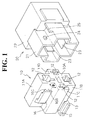
- FIGS. 1 to 6 a first embodiment of the invention is described with reference to FIGS. 1 to 6.
- Cavities 12 are formed in the respective terminal accommodating portions 11A, 11B, 11C, 11D.
- Mating connectors (not shown) are fitted or fittable into the respective cavities 12 preferably from behind, and male terminal fittings 23 of the electric part 20 are at least partially inserted or insertable thereinto preferably from the front surface side.
- the male terminal fittings 23 and mating terminal fittings are or can be connected in the cavities 12.
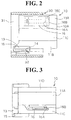
- the electric part 20 preferably has a substantially cross-shaped or star-shaped receptacle to be fitted substantially on a portion, preferably a front half of the housing 10.
- a substantially rectangular coil container 22 (electric or electronic part container) is continuously (integrally or unitarily) formed at the rear end of the receptacle 21 (right end in FIGS. 5 and 6).
- a relay coil (electric or electronic part) is accommodated (not shown) and base ends of four male terminal fittings 23 are fixed.
- the respective male terminal fittings 23 at least partially project into the receptacle 21 and are at least partially inserted or insertable into the cavities 12 with the electric part 20 and the housing 10 connected with each other.
- the arrangement of the male terminal fittings 23 and the cross-shaped housing 10 and receptacle 21 are preferably specified by the ISO standards.
- the housing 10 is mountable on a mount member 30 comprised of a plurality of substantially rectangular receptacles or hood or container 31 arranged substantially side by side which are hollow entirely along forward and backward directions.
- a mount means therefor are provided a mount portion 13 which bulges sideways on the lower surface of the terminal accommodating portion 11B at a lateral side, e.g. at the bottom of the housing 10, a step-shaped locking portion 14 formed on the lateral, preferably lower surface of the mount portion 13 (FIG. 2), and an elastically deformable lock arm 32 formed on the corresponding, preferably the lower surface of each rectangular receptacle 31.
- the housing 10 When the housing 10 is pushed into the rectangular receptacle 31 preferably from behind, the opposite ends of the mount portion 13 are guided by guide grooves 33 formed in the rectangular receptacle 31.
- stoppers 15 thereof come into contact with receiving portions 34 of the rectangular receptacle 31, substantially preventing any further movement of the housing 10 forward or in an insertion direction. Further, a backward movement of the housing 10 is restricted by the engagement of the lock arm 32 and the locking portion 14.
- the housing 10 is fixed in the rectangular receptacle 31.
- the front end of the housing 10 In this mount state, the front end of the housing 10 is substantially exposed forward or in a mating direction with the electric part 20 from the rectangular receptacle 31 (see FIG. 2). With the electric part 20 connected with the housing 10, the leading end of the receptacle 21 is at least partially accommodated in the rectangular receptacle 31.
- the housing 10 fixed or positioned in the substantially rectangular receptacle 31 as above has its upper, lower, left and right sides substantially enclosed by the inner surfaces of the rectangular receptacle 31 when viewed from the front surface side (see FIG. 4). There are left only narrow clearances between the upper surface of the upper terminal accommodating portion 11A and the upper surface of the rectangular receptacle 31, between the right side surface of the right terminal accommodating portion 11D and the right side surface of the rectangular receptacle 31, between the left side surface of the left terminal accommodating portion 11C and the left side surface of the rectangular receptacle 31.
- a locking means for locking the housing 10 and the electric part 20 in their connected state is provided in the space SL.
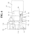
- the locking means is comprised of a lock arm 16 preferably projecting forward from a rear end position of the left side surface of the upper terminal accommodating portion 11A, and an engaging portion 24 projecting in a position of the receptacle 21 corresponding to the lock arm 16.
- a step-shaped locking portion 16A is formed at a free end (leading end) of the inner surface of the lock arm 16 facing the terminal accommodating portion 11A. This locking portion 16A is brought or bringable into engagement with the engaging portion 24 to lock the housing 10 and the electric part 20 in their connected state.
- a slanted engaging surface 16B is formed at the free end of the lock arm 16. During the connection of the housing 10 and the electric part 20, this slanted engaging surface 16B comes into contact with the engaging portion 24, and thus the lock arm 16 moves over the engaging portion 24 while smoothly undergoing an elastic deformation outward (leftward).
- the free end of the lock arm 16 is so located as to project substantially forward of the rectangular receptacle 31 (see FIGS. 2, 5 and 6). Accordingly, the lock arm 16 is not seen by being concealed by the coil container 22 of the electric part 20 when viewed from the front surface side (right side of FIGS. 5 and 6). However, the lock arm 16 can be seen from above in FIG. 4 because nothing is located thereabove, and a jig 35 can be inserted toward it.
- the jig 35 may be inserted into a clearance between the lock arm 16 and the receptacle 21 not from the front surface side, but from above, thereby elastically deforming the lock arm 16 outward so as to disengage it from the engaging portion 24.
- a slanted guide surface 16C inclined with respect to the insertion direction of the jig 35 is formed at the inner upper edge of the free end of the lock arm 16. Because of this slanted guide surface 16C, the leading end of the jig 35 can be easily inserted without being struck against the upper surface of the lock arm 16.
- a rib-shaped excessive deformation restricting or preventing portion 25 (excessive deformation restricting means) is formed such that it is located outside the free end of the lock arm 16 in the connected state with the housing 10.
- This restricting portion 25 permits an elastic deformation necessary to disengage the lock arm 16 from the engaging portion 24.
- the free end of the lock arm 16 comes into contact with the restricting portion 25 to prevent any further deformation.
- the housing 10 is fixed to the rectangular receptacle 31 by being fitted thereinto preferably from behind, and the electric part 20 is then fitted into the housing 10 preferably from behind.
- the lock arm 16 moves over the engaging portion 24 while undergoing an elastic deformation, and is engaged with the engaging portion 24 upon attaining a proper connected state. In this way, the housing 10 and the electric part 20 are locked in their connected state.
- the jig 35 is inserted from above in FIG. 4 into the clearance between the free end of the lock arm 16, which is exposed between the rectangular receptacle 31 and the electric part 20, and the left outer surface of the receptacle 21, thereby elastically deforming the lock arm 16 outward to separate it from the engaging portion 24.
- unlocking is effected and the electric part 20 can be separated from the housing 10 as it is.
- the lock arm 16 for locking the housing 10 and the electric part 20 in their connected state is provided in the rectangular dead space SL enclosed by the upper and left terminal accommodating portions 11A, 11C and the upper left corner of the rectangular receptacle 31. Accordingly, as compared with the case where the lock arm 16 is provided on the outer surface of any of the terminal accommodating portions 11A, 11B, 11C, the shape of the connector when viewed from the direction of connection is smaller.
- the jig 35 is inaccessible to the lock arm 16 along the longitudinal axis (forward and backward directions) of the rectangular receptacle 31 because of the coil container 22 standing in the way. Since the free end of the lock arm 16 projects forward from the rectangular receptacle 31 and is exposed when viewed e.g. from above in FIG. 4, unlocking of the lock arm 16 can be effected by inserting the jig 35 from above (in a direction intersecting or arranged at an angle different from 0° or 180° with the longitudinal axis of the rectangular receptacle 31).
- the lock arm 16 is formed with the slanted guide surface 16C inclined with respect to the insertion direction of the jig 35, the jig 35 can be easily brought into engagement with the lock arm 16 in particular without getting caught.
- the excessive deformation restricting portion 25 is provided to restrict an excessive deformation of the lock arm 16 in the unlocking direction, there is no likelihood that the lock arm 16 is plastically deformed by being deformed beyond its elasticity limit.
Landscapes
- Details Of Connecting Devices For Male And Female Coupling (AREA)
- Connector Housings Or Holding Contact Members (AREA)
Abstract
Description
wherein the locking means is provided in a space angularly arranged between two neighbouring terminal accommodating portions projecting indirections at an angle different from 0° and 180°.
wherein the space is defined by two neighbouring terminal accommodating portions preferably projecting in directions at an angle different from 0° and 180° and a lateral or corner portion of the receptacle.
wherein the locking means is provided in a substantially rectangular space defined by two of the terminal accommodating portions projecting in mutually substantially orthogonal directions and a corner portion of the receptacle being substantially rectangular.
wherein the locking means is provided in a substantially rectangular space defined by two of the terminal accommodating portions projecting in mutually orthogonal directions and a corner portion of the rectangular receptacle.
- 10
- Housing
- 11A
- Terminal Accommodating Portion
- 11B
- Terminal Accommodating Portion
- 11C
- Terminal Accommodating Portion
- 11D
- Terminal Accommodating Portion
- 16
- Lock Arm (Locking Means)
- 16C
- Slanted Guide Surface
- 20
- Electric Part
- 23
- Male Terminal Fitting
- 24
- Engaging Portion (Locking Means)
- 25
- Excessive Deformation Restricting Portion
(Excessive Deformation Restricting Means) - 31
- Rectangular Receptacle
- 35
- Jig
Claims (10)
- A connector, comprising:a housing (10) three or more terminal accommodating portions (11A-11D) adapted to accommodate a terminal fitting and projecting in three or more directions being angularly distributed,an electric part (20) to be connected with a engagement end surface (10A) of the housing (10), anda locking means (16; 24) for locking the housing (10) and the electric part (20) in their connected state,
wherein the locking means (16; 24) is provided in a space (SL) angularly arranged between two (11A, 11C) neighbouring terminal accommodating portions (11A-11D) projecting indirections at an angle () different from 0° and 180°. - A connector according to claim 1, further comprising a mount member (30) having a receptacle (31) into which the housing (10) are at least partially insertable,
wherein the space (SL) is defined by two (11A, 11C) neighbouring terminal accommodating portions (11A-11D)and a lateral or corner portion of the receptacle (31). - A connector according to one or more of the preceding claims, wherein the housing (10) has a substantially cross-like shape and comprises four terminal accommodating portions (11A-11D) projecting in four directions,
wherein the locking means (16; 24) is provided in a substantially rectangular space (SL) defined by two (11A, 11C) of the terminal accommodating portions (11A-11D) projecting in mutually substantially orthogonal directions and a corner portion of the receptacle (31) being substantially rectangular. - A connector according to one or more of the preceding claims including claim 2, wherein the locking means (16; 24) comprises an elastically deformable lock arm (16) having a fixed end and a free end, and an engaging portion (24) to be engaged with the lock arm (16), and wherein the free end of the lock arm (16) is arranged in such a position as to be exposed from the receptacle (31) in the connected state of the housing (10) and the electric part (20).
- A connector according to claim 4, wherein the lock arm (16) and the engaging portion (24) are unlocked by bringing a jig (35) into engagement with the lock arm (16).
- A connector according to claim 5, wherein the free end of the lock arm (16) is formed with a slanted guide surface (16C) inclined with respect to a direction (J) in which the jig (35) is brought or bringable into engagement.
- A connector according to claim 4, 5 or 6, further comprising an excessive deformation restricting means (25) for restricting a deformation of the lock arm (16) in an unlocking direction beyond a specified limit.
- A connector according to claim 7, wherein the excessive deformation restricting means (25) is provided at or on the electric part (20).
- A connector according to one or more of the preceding claims including claim 2, wherein the housing (10) are locked in the mount member (30) by mount lock means (13; 14; 32) being preferably arranged outside of the space (SL) between the two neighbouring terminal accommodation portions (11A-11D).
- A connector according to one or more of the preceding claims including claim 2, wherein two or more housings (10) can be at least partially inserted into respective receptacles (31) of the mount member (30) substantially side by side.
Applications Claiming Priority (2)
| Application Number | Priority Date | Filing Date | Title |
|---|---|---|---|
| JP10159498A JP3367417B2 (en) | 1998-04-13 | 1998-04-13 | connector |
| JP10159498 | 1998-04-13 |
Publications (3)
| Publication Number | Publication Date |
|---|---|
| EP0951101A2 true EP0951101A2 (en) | 1999-10-20 |
| EP0951101A3 EP0951101A3 (en) | 2002-01-30 |
| EP0951101B1 EP0951101B1 (en) | 2003-07-16 |
Family
ID=14304718
Family Applications (1)
| Application Number | Title | Priority Date | Filing Date |
|---|---|---|---|
| EP99106225A Expired - Lifetime EP0951101B1 (en) | 1998-04-13 | 1999-04-13 | A connector |
Country Status (5)
| Country | Link |
|---|---|
| US (1) | US6074234A (en) |
| EP (1) | EP0951101B1 (en) |
| JP (1) | JP3367417B2 (en) |
| CN (1) | CN1144319C (en) |
| DE (1) | DE69909547T2 (en) |
Cited By (2)
| Publication number | Priority date | Publication date | Assignee | Title |
|---|---|---|---|---|
| EP2961001A1 (en) * | 2014-06-25 | 2015-12-30 | Tyco Electronics AMP Korea Ltd. | Header assembly and connector for vehicle having the header assembly |
| CN106486871A (en) * | 2015-08-28 | 2017-03-08 | 住友电装株式会社 | Adapter |
Families Citing this family (19)
| Publication number | Priority date | Publication date | Assignee | Title |
|---|---|---|---|---|
| US6943661B2 (en) | 2001-10-16 | 2005-09-13 | General Electric Company | Quick-connect positive temperature coefficient of resistance resistor/overload assembly and method |
| USD543941S1 (en) * | 2005-01-31 | 2007-06-05 | Ip Holdings, Llc | Female 4 prong receptacle |
| USD544840S1 (en) * | 2005-01-31 | 2007-06-19 | Ip Holdings, Llc | Male 4 prong receptacle |
| US8109883B2 (en) | 2006-09-28 | 2012-02-07 | Tyco Healthcare Group Lp | Cable monitoring apparatus |
| US8668651B2 (en) | 2006-12-05 | 2014-03-11 | Covidien Lp | ECG lead set and ECG adapter system |
| CA2646037C (en) | 2007-12-11 | 2017-11-28 | Tyco Healthcare Group Lp | Ecg electrode connector |
| USD737979S1 (en) | 2008-12-09 | 2015-09-01 | Covidien Lp | ECG electrode connector |
| US8694080B2 (en) | 2009-10-21 | 2014-04-08 | Covidien Lp | ECG lead system |
| CA2746944C (en) | 2010-07-29 | 2018-09-25 | Tyco Healthcare Group Lp | Ecg adapter system and method |
| EP2734106B1 (en) | 2011-07-22 | 2019-09-18 | Kpr U.S., Llc | Ecg electrode connector |
| US8634901B2 (en) | 2011-09-30 | 2014-01-21 | Covidien Lp | ECG leadwire system with noise suppression and related methods |
| USD726116S1 (en) | 2013-02-20 | 2015-04-07 | Ip Holdings, Llc | Electrical plug housing |
| USD771818S1 (en) | 2013-03-15 | 2016-11-15 | Covidien Lp | ECG electrode connector |
| US9408546B2 (en) | 2013-03-15 | 2016-08-09 | Covidien Lp | Radiolucent ECG electrode system |
| DK2967396T3 (en) | 2013-03-15 | 2019-05-20 | Kpr Us Llc | ELECTRODE CONNECTOR WITH A LEADING ELEMENT |
| JP6311396B2 (en) * | 2014-03-28 | 2018-04-18 | 住友電装株式会社 | connector |
| USD758916S1 (en) | 2015-02-13 | 2016-06-14 | Ip Holdings, Llc | Planter cell |
| US10477780B2 (en) | 2015-02-13 | 2019-11-19 | Hgci, Inc. | Multiple cell tray with media plugs |
| CN112683284B (en) * | 2020-12-01 | 2024-01-02 | 北京罗克维尔斯科技有限公司 | Methods and devices for updating high-precision maps |
Family Cites Families (9)
| Publication number | Priority date | Publication date | Assignee | Title |
|---|---|---|---|---|
| US3407717A (en) * | 1965-07-12 | 1968-10-29 | Eastman Kodak Co | One-piece moldable camera socket for detachably holding a multilamp photoflash package |
| JPH0753259Y2 (en) * | 1988-02-10 | 1995-12-06 | 矢崎総業株式会社 | Connector locking mechanism |
| FR2636785B1 (en) * | 1988-09-20 | 1990-11-02 | Labinal | IMPROVEMENTS ON ELECTRICAL CONNECTION BOXES |
| JP2518968Y2 (en) * | 1992-02-06 | 1996-12-04 | 矢崎総業株式会社 | Combined connector |
| JP2593281Y2 (en) * | 1992-10-06 | 1999-04-05 | 住友電装株式会社 | connector |
| US5342215A (en) * | 1993-06-21 | 1994-08-30 | Molex Incorporated | Releasable latching system for electrical connectors |
| JP2591513Y2 (en) * | 1993-06-25 | 1999-03-03 | 住友電装株式会社 | Locking structure |
| JP2784418B2 (en) * | 1993-12-28 | 1998-08-06 | 矢崎総業株式会社 | Anti-pry connector |
| JP2907377B2 (en) * | 1994-06-03 | 1999-06-21 | 矢崎総業株式会社 | Connector connection detection device |
-
1998
- 1998-04-13 JP JP10159498A patent/JP3367417B2/en not_active Expired - Lifetime
-
1999
- 1999-04-02 CN CNB99103533XA patent/CN1144319C/en not_active Expired - Lifetime
- 1999-04-07 US US09/287,504 patent/US6074234A/en not_active Expired - Fee Related
- 1999-04-13 EP EP99106225A patent/EP0951101B1/en not_active Expired - Lifetime
- 1999-04-13 DE DE69909547T patent/DE69909547T2/en not_active Expired - Lifetime
Cited By (5)
| Publication number | Priority date | Publication date | Assignee | Title |
|---|---|---|---|---|
| EP2961001A1 (en) * | 2014-06-25 | 2015-12-30 | Tyco Electronics AMP Korea Ltd. | Header assembly and connector for vehicle having the header assembly |
| CN105305109A (en) * | 2014-06-25 | 2016-02-03 | 安普泰科电子韩国有限公司 | Head assembly and connector for a vehicle having the head assembly |
| CN105305109B (en) * | 2014-06-25 | 2019-09-10 | 安普泰科电子韩国有限公司 | Header assembly and connector for vehicle having the same |
| CN106486871A (en) * | 2015-08-28 | 2017-03-08 | 住友电装株式会社 | Adapter |
| CN106486871B (en) * | 2015-08-28 | 2019-05-03 | 住友电装株式会社 | Connector |
Also Published As
| Publication number | Publication date |
|---|---|
| JP3367417B2 (en) | 2003-01-14 |
| CN1144319C (en) | 2004-03-31 |
| DE69909547D1 (en) | 2003-08-21 |
| JPH11297420A (en) | 1999-10-29 |
| EP0951101A3 (en) | 2002-01-30 |
| CN1233086A (en) | 1999-10-27 |
| EP0951101B1 (en) | 2003-07-16 |
| US6074234A (en) | 2000-06-13 |
| DE69909547T2 (en) | 2004-05-13 |
Similar Documents
| Publication | Publication Date | Title |
|---|---|---|
| EP0951101B1 (en) | A connector | |
| EP0676828B1 (en) | Connector | |
| US6171150B1 (en) | Connector | |
| JP3789940B2 (en) | Multi-directional interface header assembly | |
| EP0386742B1 (en) | Electrical connector with socket contacts of different sizes having means for preventing erroneous connection | |
| US7114997B2 (en) | Electrical connector | |
| EP1009063A2 (en) | A connector | |
| JP2009218221A (en) | Board-to-board electrical connector assembly | |
| US4479691A (en) | Connector assembly | |
| US6942504B2 (en) | Connector | |
| US8215984B2 (en) | Electrical connector | |
| US6129574A (en) | Connector having a construction for preventing an erroneous assembling of a connector housing and a cover | |
| US20040106330A1 (en) | Connector | |
| EP1089390B1 (en) | A terminal, a joint connector and a method for assembling such a joint connector | |
| US5562495A (en) | Electric connector | |
| US5342219A (en) | Terminal-locking construction | |
| JPS6264077A (en) | Electric connector | |
| EP1134848A1 (en) | A connector and a set of terminal fittings | |
| US6488547B2 (en) | Connector with longitudinally spaced locks for retaining terminal fittings | |
| CN1236207A (en) | Shield type connector assembly | |
| US12034245B2 (en) | Hinged connector feature for terminal retainment and position assurance for high mating cycle applications | |
| US20080207030A1 (en) | Connector | |
| JP2595101Y2 (en) | Low insertion force type electrical connector | |
| JP3470026B2 (en) | Connector structure | |
| JP2004349121A (en) | Connector |
Legal Events
| Date | Code | Title | Description |
|---|---|---|---|
| PUAI | Public reference made under article 153(3) epc to a published international application that has entered the european phase |
Free format text: ORIGINAL CODE: 0009012 |
|
| 17P | Request for examination filed |
Effective date: 19990506 |
|
| AK | Designated contracting states |
Kind code of ref document: A2 Designated state(s): AT BE CH CY DE DK ES FI FR GB GR IE IT LI LU MC NL PT SE Kind code of ref document: A2 Designated state(s): DE FR |
|
| AX | Request for extension of the european patent |
Free format text: AL;LT;LV;MK;RO;SI |
|
| PUAL | Search report despatched |
Free format text: ORIGINAL CODE: 0009013 |
|
| AK | Designated contracting states |
Kind code of ref document: A3 Designated state(s): AT BE CH CY DE DK ES FI FR GB GR IE IT LI LU MC NL PT SE |
|
| AX | Request for extension of the european patent |
Free format text: AL;LT;LV;MK;RO;SI |
|
| 17Q | First examination report despatched |
Effective date: 20020523 |
|
| GRAH | Despatch of communication of intention to grant a patent |
Free format text: ORIGINAL CODE: EPIDOS IGRA |
|
| AKX | Designation fees paid |
Free format text: DE FR |
|
| GRAH | Despatch of communication of intention to grant a patent |
Free format text: ORIGINAL CODE: EPIDOS IGRA |
|
| GRAA | (expected) grant |
Free format text: ORIGINAL CODE: 0009210 |
|
| AK | Designated contracting states |
Designated state(s): DE FR |
|
| REG | Reference to a national code |
Ref country code: IE Ref legal event code: FG4D |
|
| REF | Corresponds to: |
Ref document number: 69909547 Country of ref document: DE Date of ref document: 20030821 Kind code of ref document: P |
|
| ET | Fr: translation filed | ||
| PLBE | No opposition filed within time limit |
Free format text: ORIGINAL CODE: 0009261 |
|
| STAA | Information on the status of an ep patent application or granted ep patent |
Free format text: STATUS: NO OPPOSITION FILED WITHIN TIME LIMIT |
|
| 26N | No opposition filed |
Effective date: 20040419 |
|
| REG | Reference to a national code |
Ref country code: IE Ref legal event code: MM4A |
|
| REG | Reference to a national code |
Ref country code: FR Ref legal event code: PLFP Year of fee payment: 18 |
|
| REG | Reference to a national code |
Ref country code: FR Ref legal event code: PLFP Year of fee payment: 19 |
|
| REG | Reference to a national code |
Ref country code: DE Ref legal event code: R084 Ref document number: 69909547 Country of ref document: DE |
|
| REG | Reference to a national code |
Ref country code: FR Ref legal event code: PLFP Year of fee payment: 20 |
|
| PGFP | Annual fee paid to national office [announced via postgrant information from national office to epo] |
Ref country code: FR Payment date: 20180315 Year of fee payment: 20 |
|
| PGFP | Annual fee paid to national office [announced via postgrant information from national office to epo] |
Ref country code: DE Payment date: 20180404 Year of fee payment: 20 |
|
| REG | Reference to a national code |
Ref country code: DE Ref legal event code: R071 Ref document number: 69909547 Country of ref document: DE |