EP0950745A2 - Strip matter cutting device for sewing machine - Google Patents
Strip matter cutting device for sewing machine Download PDFInfo
- Publication number
- EP0950745A2 EP0950745A2 EP99106267A EP99106267A EP0950745A2 EP 0950745 A2 EP0950745 A2 EP 0950745A2 EP 99106267 A EP99106267 A EP 99106267A EP 99106267 A EP99106267 A EP 99106267A EP 0950745 A2 EP0950745 A2 EP 0950745A2
- Authority
- EP
- European Patent Office
- Prior art keywords
- cutting
- sewing machine
- strip matter
- tape
- strip
- Prior art date
- Legal status (The legal status is an assumption and is not a legal conclusion. Google has not performed a legal analysis and makes no representation as to the accuracy of the status listed.)
- Granted
Links
- 238000009958 sewing Methods 0.000 title claims abstract description 124
- 230000009471 action Effects 0.000 claims abstract description 38
- 239000011435 rock Substances 0.000 claims abstract description 17
- 230000000694 effects Effects 0.000 claims description 3
- 230000004044 response Effects 0.000 claims description 2
- 230000037431 insertion Effects 0.000 claims 1
- 238000003780 insertion Methods 0.000 claims 1
- 230000006872 improvement Effects 0.000 abstract description 7
- 230000009467 reduction Effects 0.000 abstract description 4
- 238000010276 construction Methods 0.000 description 6
- 208000004760 Tenosynovitis Diseases 0.000 description 4
- 230000002787 reinforcement Effects 0.000 description 3
- 230000004048 modification Effects 0.000 description 2
- 238000012986 modification Methods 0.000 description 2
- 230000008859 change Effects 0.000 description 1
- 238000004140 cleaning Methods 0.000 description 1
- 238000007796 conventional method Methods 0.000 description 1
- 238000010586 diagram Methods 0.000 description 1
- 230000001747 exhibiting effect Effects 0.000 description 1
- 230000036541 health Effects 0.000 description 1
- 230000003116 impacting effect Effects 0.000 description 1
- 239000000463 material Substances 0.000 description 1
- 230000003287 optical effect Effects 0.000 description 1
- 239000003973 paint Substances 0.000 description 1
- 210000000707 wrist Anatomy 0.000 description 1
Images




Classifications
-
- D—TEXTILES; PAPER
- D05—SEWING; EMBROIDERING; TUFTING
- D05B—SEWING
- D05B37/00—Devices incorporated in sewing machines for slitting, grooving, or cutting
- D05B37/04—Cutting devices
- D05B37/08—Cutting devices with rotatable tools
Definitions
- the invention relates to a strip matter cutting device for sewing machine which is used in, for example, a sewing operation in which a strip matter, such as a tape or rubber, is sewed on the shoulders of a T-shirt and the strip matter is then cut.
- a strip matter such as a tape or rubber
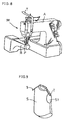
- shoulder taping sewing in sewing the shoulders of a tubular T-shirt S while sewing a tape T on the outside thereof, being generally called “shoulder taping sewing,” it is most suitable to use a vertical barrel special bed sewing machine M shown in Fig. 8.
- the shoulder taping sewing by using the bed sewing machine M can employ the following two manners which are generally called “shoulder taping feed sewing” and “shoulder taping delivery sewing”, respectively.
- an arm hole S1 of the T-shirt S is fed one after another in a direction of from front to rear of a special cylinder bed B of the bed sewing machine M, and they are allowed to pass through a pressure foot P and a sewing part H for taping sewing.
- the special cylinder bed B is full with a plurality of the T-shirts S, sewing operation is interrupted and the pressure foot P is lifted.
- a tape T extending continuously across the T-shirts S at their shoulders is cut with scissors, while taking out the separated T-shirts S along the special cylinder bed B by pulling them toward its front.
- other T-shirts S are subjected to the foregoing steps, thus repeating this taping sewing.
- a pressure foot P of a vertical barrel special bed sewing machine M is firstly lifted and a plurality of T-shirts S to be taped are pushed, through an arm hole S1, into the rear of the a special cylinder bed B as many as possible, and then held there.
- the T-shirts S are continuously delivered one by one along the cylinder bed B to its front, such that they are allowed to pass through the pressure foot P and a sewing part H for taping sewing.
- sewing operation is interrupted, and a tape T extending continuously across the T-shirts S at their shoulders is cut with scissors. Thereafter, other T-shirts S are subjected to the foregoing steps, thus repeating this taping sewing.
- a cutting device for strip matter e.g., a shoulder tape
- a throat plate 52 having a needle location 51 is secured on the top surface of a sewing machine bed (not shown), and a stationary blade 53 and a movable blade 54 are provided on the rear of the throat plate 52 in the sewing direction (the direction indicated by arrow a in Fig. 10).
- the movable blade 54 is pivoted such that it is free to shift, via a rotary cylinder 55 or the like, between a standby position at which the movable blade 54 is spaced above the stationary blade 53 as indicated by a dotted line in Fig. 11, to allow for the passage of a tape, and a cutting position at which the movable blade 54 cuts the tape in cooperation with the stationary blade 53 by rocking downwardly as indicated by a solid line in Fig. 11.
- the cutting device for tapes and the like as shown in Figs. 10 to 11, or disclosed in the Publication No. 60-48195, can be readily attached to an existing sewing machine without need for a special reconstruction therefor, so that a tape or the like is cut mechanically and automatically. This imposes on the operator less work burden and thus avoids suffering from peritendinitis.
- distance L from the needle location 51 to the cutting position is long (see Fig. 10)
- the tape losses caused in the sewing start and stop portions becomes considerably greater than that in the cutting with scissors as described.
- the cutting position is set to a point immediately behind a pressure foot. Therefore, this device permits a further reduction in tape losses than the device of Figs. 10 to 11, and that of the Publication No. 60-48195. It is, however, necessary to reconstruct a throat plate, a throat plate mount and a stationary blade so as to have a special construction. Thus it is unavoidable to increase the cost of the overall device.
- the device of Figs. 10 to 11, and those of the Publications No. 60-48195 and 7-5824 have the same problem that when they are used in sewing a wide object, a cutting part itself at which a tape or the like is cut may obstruct passage and movement of the object, failing to perform a predetermined sewing operation. This problem is, however, unsolvable even if such a cutting device is attached to a vertical barrel special bed sewing machine.
- a primary object of the invention to provide a strip matter cutting device for sewing machine which is useable by attaching to a variety of bed type sewing machines, such as a vertical barrel special bed sewing machine, a lateral barrel bed sewing machine and a flat bed type sewing machine, without need for a special reconstruction and improvement in construction, thereby permitting an increase in work efficiency and a substantial reductions in work burden.
- this cutting device is employed in sewing a wide object, a sewed strip matter is mechanically and automatically cut in the vicinity of a needle location, without constituting any obstruction to the feed of the wide object.
- a strip matter cutting device for sewing machine comprises a strip matter cutting unit having a cutting part for cutting a strip matter sewed on an object in its width direction; a cutting part shifting means for shifting the whole of the cutting part between a cutting action position closely adjacent to the rear of a needle location on the top surface of a sewing machine bed, and a non-action position at which the cutting part is retracted upwardly from the top surface of the sewing machine bed such that an object transferred along the top surface of the sewing machine bed is free to pass through the needle location; and a driving means for driving the cutting part so as to effect cutting at the cutting action position.
- the whole of the cutting part is retracted to the non-action position above the top surface of the sewing machine bed, thus constituting no obstruction to the feed of the object.
- the object and a strip matter are allowed to pass and move smoothly through the needle location in order to ensure a sewing operation including a predetermined strip matter sewing.
- the whole of the cutting part of the cutting unit is shifted to the cutting action position in the vicinity of the rear of the needle location on the top surface of the sewing machine bed, such that the strip matter is mechanically and automatically cut in a position closely adjacent to the needle location.
- the cutting device of the invention since it is arranged such that the whole of the cutting part is shifted between the cutting action position and the non-action position, no special reconstruction are required for the throat plate and throat plate mount, unlike a conventional cutting device in which a stationary blade is attached to the side of a throat plate and only a movable blade reciprocates between the cutting action position and the non-action position. Further, in the cutting device of the invention it is arranged such that impacting force upon cutting action is not directly applied to the sewing machine bed. Therefore, when it is used with a vertical barrel special bed sewing machine, a sufficient improvement in strength and durability is achieved without any reinforcement of its slender barrel cylinder bed part.
- the cutting device of the first aspect is characterized in that the cutting part of the strip matter cutting unit is provided with a pick-up portion which picks up a strip matter from the surface of the sewing machine bed in response to shift from the non-action position to the cutting action position, the strip matter picked up by the pick-up portion being subjected to cutting.
- a strip matter to be cut is picked up temporarily from the top surface of the sewing machine bed and then cut at a vertically spaced point above the top surface of the bed, thereby the cutting part and the top surface of the bed are free from damages.
- the cutting device of the second aspect is characterized in that the cutting part further comprises a strip matter receiving portion which is integrally formed with a rotary cutting blade and a pick-up portion in a continuous fashion.
- the cutting part becomes compact as a whole, and impact upon cutting is remarkably small.
- the cutting device of the first, second or third aspect is characterized in that the cutting part shifting means comprises a rock arm which is fee to rock reciprocally about a supporting point at a predetermined position, and an arm driving means for driving the rock arm to rock.
- the cutting device can be made more compact as a whole.
- the function of shifting from the non-action position to the cutting action position and the function of picking up a strip matter can be performed continuously, which permits a greatly rational operation and increase the efficiency of strip matter cutting.
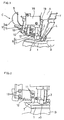
- Fig. 1 is a left perspective view of a state where a strip matter cutting unit C of the invention is attached and fixed to a sewing machine arm A of a vertical barrel special bed sewing machine M as shown in Fig. 8.
- Fig. 2 is a left side view of Fig. 1.
- a feed dog (not shown) is provided in a special cylinder bed B of the bed sewing machine M, and a throat plate 1 having a needle location (not shown) is secured to the top surface of the bed sewing machine M.
- a needle 2 which moves vertically reciprocally such as to pass through the needle location of the throat plate 1, a pressure foot 3, and a tape guide 4 with which a tape T, as an example of strip matters to be sewed on an object, is fed and guided to a sewing point.
- the tape cutting unit C is mounted on the back face of the sewing machine arm A via a blanket 5.
- the tape cutting unit C has a tape cutting part 8, a cutting part shifting means 9, and a motor 10.
- the tape cutting part 8 comprises a disk-like rotary cutting blade 6 for cutting a tape T sewed on an object in its width direction, and a tape receiving portion 7 having an approximately L-shape when viewed from front, which also forms part of a protection guard of the rotary cutting blade 6.
- the cutting part shifting means 9 shifts the whole of the tape cutting part 8 between a cutting action position (see Figs.
- the motor 10 is a driving means with which the rotary cutting blade 6 of the tape cutting part 8 is driven to rotate.
- the tip of the cutting part shifting means 9 is secured, via a screw 13, to the base of a cutting blade mount 12 to which the tape receiving portion 7 is secured via a screw 11.
- the cutting part shifting means 9 comprises a rock arm 15 of which base is supported on the blanket 5 via a pivot 14 such that it is fee to rock reciprocally about the pivot 14, and a rotary cylinder 16 which is fixedly secured to the back face of the blanket 5 and drives the rock arm 15 to rock reciprocally via the pivot 14.
- the motor 10 for driving the rotary cutting blade 6 is secured to the rock arm 15.
- the tip of the L-shaped tape receiving portion 7 of the tape cutting part 8 is tapered as shown in Fig. 3, so as to form a tape pick-up portion 17 which picks up a tape T from the top surface 1a of the throat plate 1 as shown in Fig. 4, when the whole of the tape cutting part 8 is shifted from the non-action position to the cutting action position by rocking motion of the rock arm 15 in one direction.
- the tape T picked up by the tape pick-up portion 17 is cut in its width direction by the rotary cutting blade 6 and the receiving portion 7, as shown in Fig. 5.
- the rotary cutting blade 6 is rotatably housed and held in an approximately semilunar recess 12B formed in the tip of the cutting blade mount 12.
- safety measures are taken by arranging such that a blade surface 6A does not project from a surface 12A of a circular cutting blade mount portion 12a surrounding the periphery of the blade surface 6A, and that distance 1 between the tip of the mount portion 12a and the tape pick-up portion 17 is narrow.
- an optical sensor 19 to detect the presence of an object to be sewed (materials) is attached to the sewing machine arm A immediately above the throat plate 1, via an adapter plate 18.
- a sensor means 19 detects this to change its indicator from "light” to "dark.”
- the vertical barrel special bed sewing machine M is started in rotation to feed the T-shirt S in a predetermined direction and, at the same time, to perform a predetermined sewing operation for sewing the tape T which is fed outside of the arm hole S1 via a tape guide 4.
- the indicator of the sensor 19 is changed from "dark” to "light.”
- the rotation of the sewing machine M is stopped automatically with a needle 2 located in the vicinity of the top dead center.
- a thread trimmer (not shown), a motor 10 of the tape cutting unit C, and a rotary cylinder 16 of a cutting part shifting means 9 are actuated at the same time.
- a rotary cutting blade 6 constituting a cutting part 8 is driven to rotate and a rock arm 15 is brought into rocking motion in one direction, so that the whole of the cutting part 8 is shifted from the non-action position at which the cutting part 8 is retracted upward to the left of the sewing machine arm A, to the cutting action position, as shown in Fig. 3.
- a tape pick-up portion 17 which is continuous with a receiving portion 7 picks up a tape T from the top surface 1a of a throat plate 1, as shown in Fig. 4.
- the tape T thus picked up is cut in its width direction by the rotary cutting blade 6 and the receiving portion 7, as shown in Fig. 5.
- the tape T thus cut drops on to the top surface 1a of the throat plate 1.
- the cutting part 8 Since the whole of the cutting part 8 is retracted to the non-action position upward to the left of the sewing machine arm A at the time of the shoulder taping sewing, the cutting part 8 constitutes no obstruction to the feed of the T-shirt S as an object to be sewed. Thereby, the T-shirt S is allowed to pass and move smoothly through the needle location of the throat plate 1, to ensure a predetermined taping sewing. In addition, upon termination of the taping sewing, the whole of the cutting part 8 is shifted to the cutting action position in the vicinity of the rear of the needle location of the throat plate 1 so as to cut the tape T mechanically and automatically at a position closely adjacent to the rear of the needle location.
- a thread trimmer returns to home position and comes to a stop, and the cutting part 8 of the tape cutting unit C is rocked and retracted to the non-action position upward to the left of the sewing machine arm A. Then, the actions of the motor 10 and the rotary cylinder 16 are stopped. In this case, the motor 10 retracted to the non-action position is held rotated for a predetermined time t2, thereby exhibiting a cleaning function of automatically removing tape chips and the like attached to the face of the rotary cutting blade 6.
- a presser bar lifter (not shown) is actuated to lift a pressure foot 3 automatically from the throat plate 1. While the pressure foot 3 is lifted (it is generally set to two to three seconds), the T-shirt S to which taping sewing is completed is taken out of a special cylinder bed B of the vertical barrel special bed sewing machine M to its front. After the pressure foot 3 drops down on the throat plate 1, the following T-shirt S is set and the shoulder taping sewing is started by changing the indicator of the sensor 19 to "dark.” Hereat, pedaling of the foot control is released by the time the next sewing is started.
- the cutting unit C is applicable to a sewing machine of high rotating speed.
- the cutting unit C is preferably attached to a lateral barrel covering chain stitch sewing machine M1 as shown in Fig. 12, being the second most suitable one. This enables to eliminate an inefficient and exhausting task that the operator cuts a tape with scissors, and also improve work efficiency as a whole, as in the case with the above embodiment.
Landscapes
- Engineering & Computer Science (AREA)
- Textile Engineering (AREA)
- Sewing Machines And Sewing (AREA)
Abstract
Description
Claims (8)
- A strip matter cutting device for sewing machine comprising:a strip matter cutting unit (C) having a cutting part (8) for cutting a strip matter sewed on an object in its width direction;a cutting part shifting means (9) for shifting the whole of said cutting part (8) between a cutting action position closely adjacent to the rear of a needle location on the top surface of a sewing machine bed (B), and a non-action position at which said cutting part (8) is retracted upwardly from the top surface of said sewing machine bed (B) such that said object transferred along the top surface of said sewing machine bed (B) is free to pass through said needle location; anda driving means (10) for driving said cutting part (8) to effect cutting at said cutting action position.
- A strip matter cutting device for sewing machine as defined in claim 1 wherein said cutting part (8) has a strip matter pick-up portion (17) to pick up a strip matter from the top surface of said sewing machine bed (B) in response to shift from said non-action position to said cutting action position, said strip matter picked up by said pick-up portion (17) being cut by said cutting part (8).
- A strip matter cutting device for sewing machine as defined in claim 2 wherein said cutting part (8) comprises a rotary cutting blade (6), and a strip matter receiving portion (7) continuously and integrally formed with said strip matter pick-up portion (17).
- A strip matter cutting device for sewing machine as defined in claim 1 wherein said cutting part shifting means (9) comprises a rock arm (15) which is free to rock reciprocally about a supporting point at a predetermined position, and an arm driving means for driving said rock arm (15) to rock.
- A strip matter cutting device for sewing machine as defined in claim 3 wherein said strip matter receiving portion (7) constituting said cutting part (8) is formed into an approximately L-shape when viewed from front, part of said receiving portion (7) serving as part of a protection guard of said rotary cutting blade (6), and the tip of which being tapered such as to form said pick-up portion (17).
- A strip matter cutting device for sewing machine as defined in claim 3 wherein said rotary cutting blade (6) is housed and held in an approximately semilunar recess (12B) formed in the tip of a cutting blade mount (12), such that the surface of said rotary cutting blade (6) does not project from the surface of a circular cutting blade mount portion (12a).
- A strip matter cutting device for sewing machine as defined in claim 3 wherein the gap between the tip of said circular cutting blade mount portion (12a) and said strip matter pick-up portion (17) is of such size as to prevent insertion of a finger.
- A strip matter cutting device for sewing machine as defined in claim 1 wherein said cutting part (8) is held in a driving state for cutting over a given time immediately after it is shifted from said cutting action position to said non-action position.
Applications Claiming Priority (2)
| Application Number | Priority Date | Filing Date | Title |
|---|---|---|---|
| JP14497498 | 1998-04-16 | ||
| JP10144974A JPH11300071A (en) | 1998-04-16 | 1998-04-16 | Beltlike article cutter for sewing machine |
Publications (3)
| Publication Number | Publication Date |
|---|---|
| EP0950745A2 true EP0950745A2 (en) | 1999-10-20 |
| EP0950745A3 EP0950745A3 (en) | 2000-04-26 |
| EP0950745B1 EP0950745B1 (en) | 2004-09-08 |
Family
ID=15374540
Family Applications (1)
| Application Number | Title | Priority Date | Filing Date |
|---|---|---|---|
| EP99106267A Expired - Lifetime EP0950745B1 (en) | 1998-04-16 | 1999-04-15 | Strip matter cutting device for sewing machine |
Country Status (5)
| Country | Link |
|---|---|
| US (1) | US6189469B1 (en) |
| EP (1) | EP0950745B1 (en) |
| JP (1) | JPH11300071A (en) |
| DE (1) | DE69919927T2 (en) |
| TW (1) | TW434342B (en) |
Families Citing this family (11)
| Publication number | Priority date | Publication date | Assignee | Title |
|---|---|---|---|---|
| US6722413B1 (en) * | 2000-10-26 | 2004-04-20 | Sig Pack Doboy Inc. | Cutting and laminating apparatus for producing reinforced web |
| JP4467487B2 (en) * | 2005-08-01 | 2010-05-26 | 株式会社縫技研究所 | Sewing machine cloth edge cutting device |
| JP2007068829A (en) * | 2005-09-08 | 2007-03-22 | Tokai Ind Sewing Mach Co Ltd | Cutting device in sewing machine |
| DE102006021425A1 (en) * | 2006-05-05 | 2007-11-08 | Zsk Stickmaschinen Gmbh | Separating and positioning device |
| KR101319610B1 (en) * | 2009-03-06 | 2013-10-23 | 야마토 미싱 세이조 가부시키가이샤 | Double chain stitch sewing machine having box-shaped bed |
| JP4822193B2 (en) * | 2009-03-06 | 2011-11-24 | ヤマトミシン製造株式会社 | Box bed double chain stitch machine |
| CN104213341A (en) * | 2014-09-16 | 2014-12-17 | 张文勇 | Belt-loop machine |
| CN105696203B (en) * | 2016-04-22 | 2018-12-07 | 宁波申洲针织有限公司 | A kind of automatically upper rib knitting machine |
| JP6894251B2 (en) * | 2017-02-15 | 2021-06-30 | Juki株式会社 | sewing machine |
| CN111593503A (en) * | 2020-06-15 | 2020-08-28 | 拓卡奔马机电科技有限公司 | Cutter mechanism in door front of a garment machine's slope |
| CN112853639B (en) * | 2021-01-14 | 2022-07-12 | 保定华艺帽业有限公司 | A sewing machine with automatic thread trimming function |
Family Cites Families (9)
| Publication number | Priority date | Publication date | Assignee | Title |
|---|---|---|---|---|
| US2126521A (en) * | 1934-12-10 | 1938-08-09 | Metropolitan Sewing Machine Co | Sewing machine |
| US3135229A (en) * | 1961-08-14 | 1964-06-02 | Heckethorn Mfg | Trimming attachment for sewing machines |
| US3163136A (en) * | 1962-09-10 | 1964-12-29 | Singer Co | Trimming device for sewing machine |
| AT322954B (en) | 1973-06-28 | 1975-06-25 | Triumph International Ag | CUT-OFF DEVICE FOR SEWING MACHINES |
| ATE43128T1 (en) | 1983-05-27 | 1989-06-15 | Johnson Filtration Systems | LIME SOFTENING AND CROSS-FLOW MICROFILTRATION. |
| DE3624933C3 (en) | 1986-07-23 | 1995-06-14 | Duerkopp Adler Ag | Cutting device for a sewing machine |
| IT1222861B (en) * | 1987-10-09 | 1990-09-12 | Rockwell Rimoldi Spa | SEWING MACHINE |
| US5062374A (en) | 1990-08-23 | 1991-11-05 | Clinton Industries, Inc. | Rotary thread cutter for a sewing machine |
| US5197400A (en) * | 1991-10-30 | 1993-03-30 | Kansai Special Usa Corp. | Trimming apparatus for use in making a hem |
-
1998
- 1998-04-16 JP JP10144974A patent/JPH11300071A/en active Pending
-
1999
- 1999-04-13 TW TW088105838A patent/TW434342B/en not_active IP Right Cessation
- 1999-04-13 US US09/290,857 patent/US6189469B1/en not_active Expired - Fee Related
- 1999-04-15 DE DE69919927T patent/DE69919927T2/en not_active Expired - Fee Related
- 1999-04-15 EP EP99106267A patent/EP0950745B1/en not_active Expired - Lifetime
Also Published As
| Publication number | Publication date |
|---|---|
| TW434342B (en) | 2001-05-16 |
| EP0950745B1 (en) | 2004-09-08 |
| EP0950745A3 (en) | 2000-04-26 |
| DE69919927T2 (en) | 2005-09-15 |
| JPH11300071A (en) | 1999-11-02 |
| DE69919927D1 (en) | 2004-10-14 |
| US6189469B1 (en) | 2001-02-20 |
Similar Documents
| Publication | Publication Date | Title |
|---|---|---|
| US6189469B1 (en) | Strip matter cutting device for sewing machine | |
| JPH0975575A (en) | Thread cutting device of sewing machine | |
| US4572094A (en) | Sewing machine with workpiece differential transport device | |
| CN104420083B (en) | sewing machine | |
| US4796552A (en) | Latch tacker | |
| US4763590A (en) | Residual thread chain back tacking device for overlock stitch machines | |
| EP0887452A3 (en) | Buttonhole darning sewing machine | |
| CN218321862U (en) | Backing cloth feeding mechanism capable of automatically moving along Y direction of lockstitch keyhole | |
| JP3798051B2 (en) | Automatic thread trimming machine | |
| JPS5883986A (en) | Automatic sewing machine | |
| CN2234963Y (en) | Thread-cutter for chain-shaped sewing method sewing machine | |
| CN221608344U (en) | Thread cutting head structure and sewing machine | |
| CN221501378U (en) | Automatic pulling-assisting device for computerized flat knitting machine | |
| CN220376913U (en) | Seam lifting and thread grabbing mechanism | |
| CN218621364U (en) | Automatic cleaning operation platform for sewing machine | |
| CN220724502U (en) | Lifting tooth structure of sewing machine | |
| JP2002302852A (en) | Apparatus for treating terminal yarn in flat knitting machine and method for treating the same | |
| CN212505337U (en) | Bird nest preventing device of sewing machine | |
| CN115354451B (en) | A feeder device for a pry sewing machine | |
| CN115074920B (en) | Lining and backing device for looping machine | |
| JP5416608B2 (en) | Multi-needle sewing machine with sequin supply device | |
| CN213113821U (en) | Scissors device of glove covering machine | |
| JP3908085B2 (en) | Thread cutting device for tatami mating machine | |
| CN2799611Y (en) | Thread hooking and clamping device for sewing machine | |
| JPS6335287A (en) | Differential belt feed apparatus of sewing machine |
Legal Events
| Date | Code | Title | Description |
|---|---|---|---|
| PUAI | Public reference made under article 153(3) epc to a published international application that has entered the european phase |
Free format text: ORIGINAL CODE: 0009012 |
|
| AK | Designated contracting states |
Kind code of ref document: A2 Designated state(s): DE IT |
|
| AX | Request for extension of the european patent |
Free format text: AL;LT;LV;MK;RO;SI |
|
| PUAL | Search report despatched |
Free format text: ORIGINAL CODE: 0009013 |
|
| AK | Designated contracting states |
Kind code of ref document: A3 Designated state(s): AT BE CH CY DE DK ES FI FR GB GR IE IT LI LU MC NL PT SE |
|
| AX | Request for extension of the european patent |
Free format text: AL;LT;LV;MK;RO;SI |
|
| 17P | Request for examination filed |
Effective date: 20000831 |
|
| AKX | Designation fees paid |
Free format text: DE IT |
|
| 17Q | First examination report despatched |
Effective date: 20020510 |
|
| GRAP | Despatch of communication of intention to grant a patent |
Free format text: ORIGINAL CODE: EPIDOSNIGR1 |
|
| GRAS | Grant fee paid |
Free format text: ORIGINAL CODE: EPIDOSNIGR3 |
|
| GRAA | (expected) grant |
Free format text: ORIGINAL CODE: 0009210 |
|
| AK | Designated contracting states |
Kind code of ref document: B1 Designated state(s): DE IT |
|
| REF | Corresponds to: |
Ref document number: 69919927 Country of ref document: DE Date of ref document: 20041014 Kind code of ref document: P |
|
| PLBE | No opposition filed within time limit |
Free format text: ORIGINAL CODE: 0009261 |
|
| STAA | Information on the status of an ep patent application or granted ep patent |
Free format text: STATUS: NO OPPOSITION FILED WITHIN TIME LIMIT |
|
| 26N | No opposition filed |
Effective date: 20050609 |
|
| PGFP | Annual fee paid to national office [announced via postgrant information from national office to epo] |
Ref country code: DE Payment date: 20060421 Year of fee payment: 8 |
|
| PGFP | Annual fee paid to national office [announced via postgrant information from national office to epo] |
Ref country code: IT Payment date: 20060430 Year of fee payment: 8 |
|
| PG25 | Lapsed in a contracting state [announced via postgrant information from national office to epo] |
Ref country code: DE Free format text: LAPSE BECAUSE OF NON-PAYMENT OF DUE FEES Effective date: 20071101 |
|
| PG25 | Lapsed in a contracting state [announced via postgrant information from national office to epo] |
Ref country code: IT Free format text: LAPSE BECAUSE OF NON-PAYMENT OF DUE FEES Effective date: 20070415 |