EP0950605B1 - Vorrichtung zur Verminderung von Vibrationen auf einem Schiff - Google Patents
Vorrichtung zur Verminderung von Vibrationen auf einem Schiff Download PDFInfo
- Publication number
- EP0950605B1 EP0950605B1 EP99400926A EP99400926A EP0950605B1 EP 0950605 B1 EP0950605 B1 EP 0950605B1 EP 99400926 A EP99400926 A EP 99400926A EP 99400926 A EP99400926 A EP 99400926A EP 0950605 B1 EP0950605 B1 EP 0950605B1
- Authority
- EP
- European Patent Office
- Prior art keywords
- shafts
- signal
- angular offset
- regulation
- offset
- Prior art date
- Legal status (The legal status is an assumption and is not a legal conclusion. Google has not performed a legal analysis and makes no representation as to the accuracy of the status listed.)
- Expired - Lifetime
Links
- 238000005259 measurement Methods 0.000 claims description 4
- 230000004048 modification Effects 0.000 claims description 4
- 238000012986 modification Methods 0.000 claims description 4
- 102100023882 Endoribonuclease ZC3H12A Human genes 0.000 claims description 2
- 101710112715 Endoribonuclease ZC3H12A Proteins 0.000 claims description 2
- 101001096074 Homo sapiens Regenerating islet-derived protein 4 Proteins 0.000 claims description 2
- 108700012361 REG2 Proteins 0.000 claims description 2
- 101150108637 REG2 gene Proteins 0.000 claims description 2
- 108091058543 REG3 Proteins 0.000 claims description 2
- 101100120298 Rattus norvegicus Flot1 gene Proteins 0.000 claims description 2
- 101100412403 Rattus norvegicus Reg3b gene Proteins 0.000 claims description 2
- 102100027336 Regenerating islet-derived protein 3-alpha Human genes 0.000 claims description 2
- 102100037889 Regenerating islet-derived protein 4 Human genes 0.000 claims description 2
- QGVYYLZOAMMKAH-UHFFFAOYSA-N pegnivacogin Chemical compound COCCOC(=O)NCCCCC(NC(=O)OCCOC)C(=O)NCCCCCCOP(=O)(O)O QGVYYLZOAMMKAH-UHFFFAOYSA-N 0.000 claims description 2
- 239000003990 capacitor Substances 0.000 description 4
- 238000009795 derivation Methods 0.000 description 3
- 238000000034 method Methods 0.000 description 3
- XLYOFNOQVPJJNP-UHFFFAOYSA-N water Substances O XLYOFNOQVPJJNP-UHFFFAOYSA-N 0.000 description 3
- 230000003993 interaction Effects 0.000 description 2
- 230000004044 response Effects 0.000 description 2
- 238000004364 calculation method Methods 0.000 description 1
- 230000008859 change Effects 0.000 description 1
- 230000006835 compression Effects 0.000 description 1
- 238000007906 compression Methods 0.000 description 1
- 238000013461 design Methods 0.000 description 1
- 238000010586 diagram Methods 0.000 description 1
- 238000001914 filtration Methods 0.000 description 1
- 230000006872 improvement Effects 0.000 description 1
- 210000000056 organ Anatomy 0.000 description 1
- 238000012549 training Methods 0.000 description 1
- 230000007704 transition Effects 0.000 description 1
Images
Classifications
-
- B—PERFORMING OPERATIONS; TRANSPORTING
- B63—SHIPS OR OTHER WATERBORNE VESSELS; RELATED EQUIPMENT
- B63H—MARINE PROPULSION OR STEERING
- B63H21/00—Use of propulsion power plant or units on vessels
- B63H21/30—Mounting of propulsion plant or unit, e.g. for anti-vibration purposes
-
- B—PERFORMING OPERATIONS; TRANSPORTING
- B63—SHIPS OR OTHER WATERBORNE VESSELS; RELATED EQUIPMENT
- B63H—MARINE PROPULSION OR STEERING
- B63H21/00—Use of propulsion power plant or units on vessels
- B63H21/30—Mounting of propulsion plant or unit, e.g. for anti-vibration purposes
- B63H21/302—Mounting of propulsion plant or unit, e.g. for anti-vibration purposes with active vibration damping
-
- F—MECHANICAL ENGINEERING; LIGHTING; HEATING; WEAPONS; BLASTING
- F16—ENGINEERING ELEMENTS AND UNITS; GENERAL MEASURES FOR PRODUCING AND MAINTAINING EFFECTIVE FUNCTIONING OF MACHINES OR INSTALLATIONS; THERMAL INSULATION IN GENERAL
- F16F—SPRINGS; SHOCK-ABSORBERS; MEANS FOR DAMPING VIBRATION
- F16F15/00—Suppression of vibrations in systems; Means or arrangements for avoiding or reducing out-of-balance forces, e.g. due to motion
- F16F15/02—Suppression of vibrations of non-rotating, e.g. reciprocating systems; Suppression of vibrations of rotating systems by use of members not moving with the rotating systems
Definitions
- the present invention relates to a device for reduce vibrations on a boat with two shafts propulsion.
- the present invention thus relates to a device to reduce vibration that does not support constraints or limitations discussed above.
- this device adapted to a boat provided with at least two propulsion shafts has means for controlling the angular difference of the two shafts on a deposit; it also includes means of calibration to find an optimal angular offset between these trees which corresponds to a minimum of vibrations, and control means for actuating successively, in response to a control signal, the calibration means then the servo means by setting as instructions this optimal angular offset.
- the invention finds an advantageous application when the propulsion shafts are powered by motors electric.
- the device comprises means measurement to derive the angular deviation of the parameters supply of these motors.
- the angular offset optimal is detected by ear.
- the device comprises plus a vibration sensor to detect the offset optimal angular.
- the regulation signal represents the derived from the fundamental level of vibrations.
- control signal is activated following a modification of the operating conditions of the boat.
- this modification concerns either the rotational speed, i.e. the power transmitted to one of the trees.
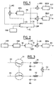
- the device comprises a COM control circuit which receives the different relevant information and orders the other organs of as described below.
- This is for example a microprocessor.
- a first regulator REG1 regulates the speed of rotation of a first propulsion shaft producing a first supply signal AL1 to the motor of this tree. It receives as input difference between a speed reference CR supplied by the COM control circuit and the speed of measured rotation MR1 of this tree.
- a second regulator REG2 regulates the speed of rotation of a second propulsion shaft producing a second supply signal AL2 to the motor of this tree. It receives as input difference between, on the one hand, the sum of the rotation speed CR and a positioning signal relative PR and, on the other hand, the rotation speed MR2 of this second tree.
- the relative positioning signal PR is produced by a third REG3 regulator, of the proportional integral type for example, who receives as input the difference of angular offset setpoint CD from the circuit COM command and the measured angular difference MD between the two propulsion shafts.
- the measurement signals MR1, MR2, MD relating to the speed of rotation of the trees or their angular deviation can be obtained by means of position encoders arranged on these trees.
- the COM control circuit In a first calibration phase, in response to a CC control signal, the COM control circuit produces a ramp as angular offset setpoint CD so that the measured angular difference MD be gradually increased by 360 °. When a minimum of vibrations is detected, the control circuit memorizes the value corresponding to the angular difference which then represents a optimal offset DO.
- the minimum vibration can be detected at the ear, by an experienced man.
- This first phase can possibly be repeated one or more times to improve accuracy, this by taking the average value of the different levels for a given offset. Again, this is a technique widespread which will not be described further.
- phase servo the COM control circuit produces the value of this optimal offset DO as offset setpoint angular CD. It follows that the two propulsion shafts are slaved so that they have an angular deviation equal to the optimal offset.
- control signal CC can be produced manually by qualified personnel, the captain for example. But this signal can also be produced automatically when certain operating conditions are changed, if only than the speed setpoint CR or the power supplied to a drive motor.
- the two trees are therefore enslaved in angular deviation on a value constant which corresponds to a minimum of vibrations for operating conditions present during the calibration.
- the invention proposes a third phase said regulation phase during which the optimal offset is constantly updated by means of a chain of regulation.
- the vibration sensor VIB is followed by a PBF filtering module which isolates the fundamental component of the sensor output signal and produces an NI level signal representative of the amplitude of this component.
- a DER bypass module is provided to realize a NI level signal derivation function by ratio to the measured angular deviation MD. It is indeed about regulate to a minimum, the minimum value of NI level signal, and one of the possible methods is to take the derivative of the relevant function and to regulate with respect to a VR reference value equal to zero.
- the module derivation performs the time derivative dNI of the signal NI level, the time derivative dMD of the angular deviation measured MD and produces a DI bypass signal equal to ratio of the first to the second derivative DNI / dMD.
- one can adopt a discretized representation of the different variables where i represents the time increment and, by indexing these variables by the discretized time i, one can calculate the derivation signal DI by means of the following expression : DI i OR i -OR i-1 MD i Md i-1
- a fourth REG4 regulator receives as input the difference in the value of VR reference (equal to zero by assumption) and of the signal DI bypass to produce an RS regulation signal.
- the circuit COM command starts the regulation phase during which the angular offset setpoint CD will pass gradually from the optimal offset value DO acquired during the calibration phase at the signal value of RS regulation.
- b (t) 1-a (t). It is possible to perform this function digitally at within the control circuit.
- the first switch S1 receiving on the one hand the optimal offset DO is connected on the other hand to the first terminals of a first capacitor C1 and a first resistance R1.
- the second terminal of the first capacitor C1 is connected to ground while that of the first resistance R1 is injected on an input of a circuit SUM addition.
- the second switch S2 receiving on the one hand the RS control signal is also connected to the first terminals of a second capacitor C2 and of a second resistance R2.
- the second terminal of the second capacitor C2 is connected to ground while that of the second resistance R2 is injected on another input of the SUM addition circuit.
- control circuit reverses the first S1 respectively the second S2 switch which pass from the closed state respectively open to the state open respectively closed.
Landscapes
- Engineering & Computer Science (AREA)
- Mechanical Engineering (AREA)
- General Engineering & Computer Science (AREA)
- Chemical & Material Sciences (AREA)
- Combustion & Propulsion (AREA)
- Ocean & Marine Engineering (AREA)
- Acoustics & Sound (AREA)
- Aviation & Aerospace Engineering (AREA)
- Physics & Mathematics (AREA)
- Vibration Prevention Devices (AREA)
- Control Of Electric Motors In General (AREA)
- Control Of Position Or Direction (AREA)
- Control Of Multiple Motors (AREA)
- Feedback Control In General (AREA)
Claims (9)
- Vorrichtung zum Vermindern der Vibrationen auf einem mit wenigstens zwei Antriebswellen ausgerüsteten Schiff, mit Mitteln (REG1, REG2, REG3) zur Nachführung der Winkelabweichung (MD) der Wellen wenigstens auf einen Sollwert (CD), dadurch gekennzeichnet, dass sie Kalibriermittel zum Auffinden einer optimalen Winkelverschiebung (DO) zwischen diesen Wellen, welche einem Minimum der Vibrationen entspricht, und Steuermittel (COM), um als Antwort auf ein Steuersignal (CC) die Kalibriermittel und anschließend die Nachführmittel sukzessiv zu betätigen, wobei als Sollwert (CD) die optimale Winkelverschiebung (DO) festgelegt wird, umfasst.
- Vorrichtung nach Anspruch 1, dadurch gekennzeichnet, dass sie, wenn die Wellen von Elektromotoren angetrieben werden, Messmittel umfasst, um die Winkelabweichung (MD) von Versorgungsparametern der Motoren abzuleiten.
- Vorrichtung nach einem der Ansprüche 1 und 2, dadurch gekennzeichnet, dass die optimale Winkelverschiebung (DO) mit dem Gehör erfasst wird.
- Vorrichtung nach einem der Ansprüche 1 und 2, dadurch gekennzeichnet, dass sie zudem einen Vibrationsaufnehmer (VIB) zum Erfassen der optimalen Winkelverschiebung (DO) umfasst.
- Vorrichtung nach Anspruch 4, dadurch gekennzeichnet, dass sie eine Regelkette (PBF, DER, REG4) zum Erzeugen eines die Variationen der Höhe der Vibrationen darstellenden Regelsignals (RS) umfasst, wobei die Steuermittel (COM) das Regelsignal (RS) nach der optimalen Winkelverschiebung (DO) als Sollwert (CD) festlegen.
- Vorrichtung nach Anspruch 5, dadurch gekennzeichnet, dass das Regelsignal (RS) die Ableitung der Grundhöhe der Vibrationen darstellt.
- Vorrichtung nach einem der vorhergehenden Ansprüche, dadurch gekennzeichnet, dass das Steuersignal (CC) manuell betätigt wird.
- Vorrichtung nach einem der vorhergehenden Ansprüche. dadurch gekennzeichnet, dass das Steuersignal (CC)in Bezug auf eine Änderung der Funktionsbedingungen des Schiffs betätigt wird.
- Vorrichtung nach Anspruch 8, dadurch gekennzeichnet, dass die Änderung entweder die Drehgeschwindigkeit oder die auf eine der Wellen übertragene Leistung betrifft.
Applications Claiming Priority (2)
| Application Number | Priority Date | Filing Date | Title |
|---|---|---|---|
| FR9804752A FR2777534B1 (fr) | 1998-04-16 | 1998-04-16 | Dispositif pour reduire les vibrations sur un bateau |
| FR9804752 | 1998-04-16 |
Publications (2)
| Publication Number | Publication Date |
|---|---|
| EP0950605A1 EP0950605A1 (de) | 1999-10-20 |
| EP0950605B1 true EP0950605B1 (de) | 2003-12-03 |
Family
ID=9525308
Family Applications (1)
| Application Number | Title | Priority Date | Filing Date |
|---|---|---|---|
| EP99400926A Expired - Lifetime EP0950605B1 (de) | 1998-04-16 | 1999-04-15 | Vorrichtung zur Verminderung von Vibrationen auf einem Schiff |
Country Status (8)
| Country | Link |
|---|---|
| US (1) | US6190217B1 (de) |
| EP (1) | EP0950605B1 (de) |
| KR (1) | KR19990083275A (de) |
| DE (1) | DE69913235T2 (de) |
| ES (1) | ES2212841T3 (de) |
| FR (1) | FR2777534B1 (de) |
| PT (1) | PT950605E (de) |
| TR (1) | TR199900849A3 (de) |
Families Citing this family (2)
| Publication number | Priority date | Publication date | Assignee | Title |
|---|---|---|---|---|
| FI20030556A0 (fi) * | 2003-04-11 | 2003-04-11 | Abb Oy | Menetelmä ja laitteisto laivan ohjaamiseksi |
| CN103303453B (zh) * | 2013-04-28 | 2015-09-30 | 哈尔滨工程大学 | 一种适用于动力装置复杂隔振系统的主动抗冲击模糊方法 |
Family Cites Families (3)
| Publication number | Priority date | Publication date | Assignee | Title |
|---|---|---|---|---|
| US5049795A (en) * | 1990-07-02 | 1991-09-17 | Westinghouse Electric Corp. | Multivariable adaptive vibration canceller |
| US5148402A (en) * | 1990-12-21 | 1992-09-15 | United Technologies Corporation | Method for reducing aircraft cabin noise and vibration |
| DE4116647C5 (de) * | 1991-05-22 | 2004-07-08 | Hess Maschinenfabrik Gmbh & Co. Kg | Rüttelvorrichtung |
-
1998
- 1998-04-16 FR FR9804752A patent/FR2777534B1/fr not_active Expired - Fee Related
-
1999
- 1999-04-15 DE DE69913235T patent/DE69913235T2/de not_active Expired - Fee Related
- 1999-04-15 US US09/292,338 patent/US6190217B1/en not_active Expired - Fee Related
- 1999-04-15 ES ES99400926T patent/ES2212841T3/es not_active Expired - Lifetime
- 1999-04-15 PT PT99400926T patent/PT950605E/pt unknown
- 1999-04-15 EP EP99400926A patent/EP0950605B1/de not_active Expired - Lifetime
- 1999-04-16 TR TR1999/00849A patent/TR199900849A3/tr unknown
- 1999-04-16 KR KR1019990013644A patent/KR19990083275A/ko not_active Abandoned
Also Published As
| Publication number | Publication date |
|---|---|
| FR2777534B1 (fr) | 2000-06-23 |
| DE69913235D1 (de) | 2004-01-15 |
| TR199900849A2 (xx) | 1999-11-22 |
| US6190217B1 (en) | 2001-02-20 |
| ES2212841T3 (es) | 2004-08-01 |
| TR199900849A3 (tr) | 1999-11-22 |
| KR19990083275A (ko) | 1999-11-25 |
| FR2777534A1 (fr) | 1999-10-22 |
| DE69913235T2 (de) | 2004-09-02 |
| PT950605E (pt) | 2004-04-30 |
| EP0950605A1 (de) | 1999-10-20 |
Similar Documents
| Publication | Publication Date | Title |
|---|---|---|
| FR2553596A1 (fr) | Systeme d'actionnement d'helice de moteur | |
| FR2717763A1 (fr) | Système de direction assistée actionné par un moteur à courant continu pour véhicule à moteur. | |
| FR2655942A1 (fr) | Dispositif de commande de la position d'un engin spatial avec compensation du frotttement d'une roue de reaction. | |
| FR2875345A1 (fr) | Systeme de detection de defaillance pour onduleur | |
| EP0058609A1 (de) | Regelverfahren der Speisung eines Gleichstrommotors und Vorrichtung zu dessen Ausführung | |
| EP1974455B1 (de) | Vorrichtung zur steuerung einer polyphasen-rotationsmaschine | |
| EP2124327A2 (de) | Vorrichtung zur Bestimmung der Neigungsposition eines Rotors einer mehrphasigen elektrisch umlaufenden Maschine und eine solche Vorrichtung umfassende elektrisch umlaufende Maschine | |
| EP0950605B1 (de) | Vorrichtung zur Verminderung von Vibrationen auf einem Schiff | |
| EP0802464B1 (de) | Verfahren zur Steuerung des Erregungstroms eines Fahrzeuggenerators mit digitaler Verarbeitung und Steuerungsvorrichtung zur Durchführung dieses Verfahrens | |
| EP0834983A2 (de) | Anordnung zur Strommessung in einem Wechselrichter | |
| EP4216424A1 (de) | Verfahren und system zur steuerung einer von einem wechselrichter gesteuerten elektrischen maschine mit mehreren schaltarmen mit zwei servoverfahren | |
| CA2566909A1 (fr) | Dispositif de commande d'une machine electrique tournante | |
| EP1406141B1 (de) | Verfahren und Einrichtung zur automatischen Steuerung des Schubes eines Flugzeugantriebes | |
| EP0904632B1 (de) | Regelvorrichtung eines elektrischen motors für eine servolenkung | |
| FR2620243A1 (fr) | Procede de reacquisition de la position de tangage d'un satellite terrestre | |
| EP3778372A1 (de) | Wasserfahrzeug, wie beispielsweise ein surfbrett oder paddelbrett, mit kontrollierter elektrischer unterstützung | |
| FR3107367A1 (fr) | Mesure de fonction de transferts dans un système mécatronique | |
| EP0642209A1 (de) | Startvorrichtung, für eine Turbine, insbesondere eine Gasturbine | |
| EP1544078A1 (de) | Elektro-hydraulisches Servolenkungssystem für ein Kraftfahrzeug | |
| EP0469509A1 (de) | Verfahren und Vorrichtung zur Steuerung eines Asynchronmotors durch Regelung des magnetischen Induktionsflusses | |
| EP1408385B1 (de) | Verfahren zur Steuerung eines dynamischen Systems mit Hilfe eines Fuzzy-Logic-Modells wenigstens einer inversen Übertragungsfunktion des Systems | |
| EP0267990A1 (de) | Regeleinrichtung für ein Fahrzeug mit elektrischer Kraftübertragung | |
| FR3038724B1 (fr) | Dispositif de mesure d'une vitesse relative de rotation et/ou d'une position angulaire relative entre deux elements tournants | |
| EP0788220A1 (de) | Umrechter zur Speisung eines Elektromotors zum Antrieb eines Fahrzeugs | |
| FR3128598A1 (fr) | Procédé de calage automatique d'un capteur de position angulaire |
Legal Events
| Date | Code | Title | Description |
|---|---|---|---|
| PUAI | Public reference made under article 153(3) epc to a published international application that has entered the european phase |
Free format text: ORIGINAL CODE: 0009012 |
|
| AK | Designated contracting states |
Kind code of ref document: A1 Designated state(s): BE DE ES FI FR GB GR NL PT SE |
|
| AX | Request for extension of the european patent |
Free format text: AL;LT;LV;MK;RO;SI |
|
| 17P | Request for examination filed |
Effective date: 20000420 |
|
| AKX | Designation fees paid |
Free format text: BE DE ES FI FR GB GR NL PT SE |
|
| GRAH | Despatch of communication of intention to grant a patent |
Free format text: ORIGINAL CODE: EPIDOS IGRA |
|
| RIN1 | Information on inventor provided before grant (corrected) |
Inventor name: NICOD, JEAN-PHILIPPE Inventor name: HUOT-MARCHAND, JEAN-PIERRE |
|
| GRAS | Grant fee paid |
Free format text: ORIGINAL CODE: EPIDOSNIGR3 |
|
| GRAA | (expected) grant |
Free format text: ORIGINAL CODE: 0009210 |
|
| AK | Designated contracting states |
Kind code of ref document: B1 Designated state(s): BE DE ES FI FR GB GR NL PT SE |
|
| REG | Reference to a national code |
Ref country code: GB Ref legal event code: FG4D Free format text: NOT ENGLISH |
|
| REF | Corresponds to: |
Ref document number: 69913235 Country of ref document: DE Date of ref document: 20040115 Kind code of ref document: P |
|
| REG | Reference to a national code |
Ref country code: SE Ref legal event code: TRGR |
|
| GBT | Gb: translation of ep patent filed (gb section 77(6)(a)/1977) |
Effective date: 20040317 |
|
| REG | Reference to a national code |
Ref country code: GR Ref legal event code: EP Ref document number: 20040400797 Country of ref document: GR |
|
| REG | Reference to a national code |
Ref country code: PT Ref legal event code: SC4A Free format text: AVAILABILITY OF NATIONAL TRANSLATION Effective date: 20040220 |
|
| REG | Reference to a national code |
Ref country code: ES Ref legal event code: FG2A Ref document number: 2212841 Country of ref document: ES Kind code of ref document: T3 |
|
| PLBE | No opposition filed within time limit |
Free format text: ORIGINAL CODE: 0009261 |
|
| STAA | Information on the status of an ep patent application or granted ep patent |
Free format text: STATUS: NO OPPOSITION FILED WITHIN TIME LIMIT |
|
| 26N | No opposition filed |
Effective date: 20040906 |
|
| PGFP | Annual fee paid to national office [announced via postgrant information from national office to epo] |
Ref country code: PT Payment date: 20060327 Year of fee payment: 8 |
|
| PGFP | Annual fee paid to national office [announced via postgrant information from national office to epo] |
Ref country code: FR Payment date: 20060411 Year of fee payment: 8 |
|
| PGFP | Annual fee paid to national office [announced via postgrant information from national office to epo] |
Ref country code: SE Payment date: 20060413 Year of fee payment: 8 Ref country code: NL Payment date: 20060413 Year of fee payment: 8 |
|
| PGFP | Annual fee paid to national office [announced via postgrant information from national office to epo] |
Ref country code: FI Payment date: 20060418 Year of fee payment: 8 |
|
| PGFP | Annual fee paid to national office [announced via postgrant information from national office to epo] |
Ref country code: DE Payment date: 20060419 Year of fee payment: 8 |
|
| PGFP | Annual fee paid to national office [announced via postgrant information from national office to epo] |
Ref country code: GB Payment date: 20060420 Year of fee payment: 8 |
|
| PGFP | Annual fee paid to national office [announced via postgrant information from national office to epo] |
Ref country code: ES Payment date: 20060427 Year of fee payment: 8 |
|
| PGFP | Annual fee paid to national office [announced via postgrant information from national office to epo] |
Ref country code: GR Payment date: 20060428 Year of fee payment: 8 |
|
| PGFP | Annual fee paid to national office [announced via postgrant information from national office to epo] |
Ref country code: BE Payment date: 20060502 Year of fee payment: 8 |
|
| REG | Reference to a national code |
Ref country code: PT Ref legal event code: MM4A Free format text: LAPSE DUE TO NON-PAYMENT OF FEES Effective date: 20071015 |
|
| GBPC | Gb: european patent ceased through non-payment of renewal fee |
Effective date: 20070415 |
|
| BERE | Be: lapsed |
Owner name: S.A. *ALSTOM ENTREPRISE Effective date: 20070430 |
|
| NLV4 | Nl: lapsed or anulled due to non-payment of the annual fee |
Effective date: 20071101 |
|
| PG25 | Lapsed in a contracting state [announced via postgrant information from national office to epo] |
Ref country code: PT Free format text: LAPSE BECAUSE OF NON-PAYMENT OF DUE FEES Effective date: 20071015 Ref country code: NL Free format text: LAPSE BECAUSE OF NON-PAYMENT OF DUE FEES Effective date: 20071101 Ref country code: FI Free format text: LAPSE BECAUSE OF NON-PAYMENT OF DUE FEES Effective date: 20070415 Ref country code: DE Free format text: LAPSE BECAUSE OF NON-PAYMENT OF DUE FEES Effective date: 20071101 |
|
| PG25 | Lapsed in a contracting state [announced via postgrant information from national office to epo] |
Ref country code: BE Free format text: LAPSE BECAUSE OF NON-PAYMENT OF DUE FEES Effective date: 20070430 |
|
| PG25 | Lapsed in a contracting state [announced via postgrant information from national office to epo] |
Ref country code: GB Free format text: LAPSE BECAUSE OF NON-PAYMENT OF DUE FEES Effective date: 20070415 |
|
| PG25 | Lapsed in a contracting state [announced via postgrant information from national office to epo] |
Ref country code: SE Free format text: LAPSE BECAUSE OF NON-PAYMENT OF DUE FEES Effective date: 20070416 |
|
| REG | Reference to a national code |
Ref country code: ES Ref legal event code: FD2A Effective date: 20070416 |
|
| PG25 | Lapsed in a contracting state [announced via postgrant information from national office to epo] |
Ref country code: FR Free format text: LAPSE BECAUSE OF NON-PAYMENT OF DUE FEES Effective date: 20070430 |
|
| PG25 | Lapsed in a contracting state [announced via postgrant information from national office to epo] |
Ref country code: GR Free format text: LAPSE BECAUSE OF NON-PAYMENT OF DUE FEES Effective date: 20071102 Ref country code: ES Free format text: LAPSE BECAUSE OF NON-PAYMENT OF DUE FEES Effective date: 20070416 |