EP0950491A2 - Lined article for the inside paneling of automobiles and procedure for its production - Google Patents
Lined article for the inside paneling of automobiles and procedure for its production Download PDFInfo
- Publication number
- EP0950491A2 EP0950491A2 EP99105709A EP99105709A EP0950491A2 EP 0950491 A2 EP0950491 A2 EP 0950491A2 EP 99105709 A EP99105709 A EP 99105709A EP 99105709 A EP99105709 A EP 99105709A EP 0950491 A2 EP0950491 A2 EP 0950491A2
- Authority
- EP
- European Patent Office
- Prior art keywords
- film
- carrier
- edges
- area
- areas
- Prior art date
- Legal status (The legal status is an assumption and is not a legal conclusion. Google has not performed a legal analysis and makes no representation as to the accuracy of the status listed.)
- Pending
Links
Images

Classifications
-
- B—PERFORMING OPERATIONS; TRANSPORTING
- B29—WORKING OF PLASTICS; WORKING OF SUBSTANCES IN A PLASTIC STATE IN GENERAL
- B29C—SHAPING OR JOINING OF PLASTICS; SHAPING OF MATERIAL IN A PLASTIC STATE, NOT OTHERWISE PROVIDED FOR; AFTER-TREATMENT OF THE SHAPED PRODUCTS, e.g. REPAIRING
- B29C44/00—Shaping by internal pressure generated in the material, e.g. swelling or foaming ; Producing porous or cellular expanded plastics articles
- B29C44/02—Shaping by internal pressure generated in the material, e.g. swelling or foaming ; Producing porous or cellular expanded plastics articles for articles of definite length, i.e. discrete articles
- B29C44/12—Incorporating or moulding on preformed parts, e.g. inserts or reinforcements
- B29C44/1257—Joining a preformed part and a lining, e.g. around the edges
-
- B—PERFORMING OPERATIONS; TRANSPORTING
- B29—WORKING OF PLASTICS; WORKING OF SUBSTANCES IN A PLASTIC STATE IN GENERAL
- B29C—SHAPING OR JOINING OF PLASTICS; SHAPING OF MATERIAL IN A PLASTIC STATE, NOT OTHERWISE PROVIDED FOR; AFTER-TREATMENT OF THE SHAPED PRODUCTS, e.g. REPAIRING
- B29C44/00—Shaping by internal pressure generated in the material, e.g. swelling or foaming ; Producing porous or cellular expanded plastics articles
- B29C44/02—Shaping by internal pressure generated in the material, e.g. swelling or foaming ; Producing porous or cellular expanded plastics articles for articles of definite length, i.e. discrete articles
- B29C44/12—Incorporating or moulding on preformed parts, e.g. inserts or reinforcements
- B29C44/14—Incorporating or moulding on preformed parts, e.g. inserts or reinforcements the preformed part being a lining
Definitions
- the invention relates to a molded part according to the preamble of claim 1, and a method for its production.
- Foam-backed are used to improve the feel Foils (foils with applied scaum backs) are used, the foam backing is approx. 2 mm thick, thicker "safety pads” realized with foam pads (Foam fittings), which, prefabricated separately, on the corresponding areas of the carrier part are glued.
- the lamination is done with the help of glue (Adhesion promoters) applied and in separate tools “folded”, i.e. glued around the edges of the carrier part.
- Thin foam backs on the laminating film also have the disadvantage that fineness of the molded part contour "blurring", ie only poorly reproduced, the use of prefabricated "pads" is cumbersome and expensive.
- the air permeability of the carrier part if necessary through supports an additional perforation in the fold area, ensures that the foam also in the fold area passes through and ensures a secure fixation of the fold. All-over air permeability of the carrier part is there optimal. Wood and natural fiber composites are from Naturally permeable to air, they can be locally (in Fold area) so porous that a foam penetration no problems in the area of folding. A possible loss of strength of the support part is thereby due to the impregnation of the porous area Foam at least compensated.
- the lamination film is used by deep drawing or a corresponding slush technique in a separate, upstream operation with oversize manufactured.
- the edges in the area of the later fold so, it has undercuts, but not yet have the final fold shape that they have in the finished Should have product.
- the protruding edges, i.e. the excess, are then cut off so that the film with their final dimensions and almost theirs final form.
- This slide is then in the area the already more or less bent edges the carrier inserted and pressed in.
- the folded edges practically form undercuts into which the carrier is pressed becomes.
- the fold is made when producing the film preformed and then through the upper top of the mold brought into its final form.
- the permanent one Connection between the finished bent edges and the Carrier then takes place through the polyurethane.
- the carrier is permeable to air so that the air when entering the polyurethane can escape.
- the carrier can not only be permeable to air, but also be porous that more or less much Push the polyurethane through before chemically reacting can to ensure the desired gluing.
- One on under usual injection of the undeveloped foam under Overpressure in the closed foaming tool favors the foam distribution considerably, so that even flat areas, which are only thinly foamed (approx. only 2 mm) without problems are realizable.
- the production takes place the inner lining completely in the mold, i.e. the bending to the final desired shape is done by the top of the mold. In some complicated ones Corner areas, it may be that special folding tools for Come into play. But this is an exceptional case.
- the film 1 is produced by deep drawing with oversize 1a.
- protrusions or Knobs 2 can be provided, the later fixation of the Serve carrier and can in particular be provided there, where there is an opening in the final product, e.g. to accommodate a loudspeaker in the door. These sections are then removed.
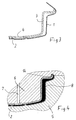
- Fig. 3 is a carrier 3 made of air-permeable or porous Material inserted or pressed into the film 1.
- the edges of the carrier lie in the bent edges the slide.
- the projections 2 provide support for the Carrier and a fixation, so that a space for receiving the Polyurethane remains free.
- the composite shown in Fig. 3 is then in the lower part 5 of an appropriately designed mold and fixed by vacuum. Now the upper part 6 is retracted and presses the bent edges of the film into the final form 1b. When the mold is closed, is through a channel 7 and an opening 4 in the carrier introduced the polyurethane. This foams and forms the foam-backed areas 8 and ensures gluing in the area of the completely bent edge 1b. A certain one Porosity of the carrier 3, particularly in this area, supports the bonding.
- the composite in the film already has the final dimensions and the fold already is present but not yet in its final form, placed in the lower part 5 of the mold and the upper part 6 is retracted, the fold will be in its final form 1b brought.
- the polyurethane By introducing the polyurethane the desired foamed sections 8 of the interior trim and at the same time the Gluing in the area of the bent edges.
Landscapes
- Vehicle Interior And Exterior Ornaments, Soundproofing, And Insulation (AREA)
- Casting Or Compression Moulding Of Plastics Or The Like (AREA)
Abstract
Description
Die Erfindung betrifft ein Formteil gemäß dem Oberbegriff
des Anspruches 1, sowie ein Verfahren zu seiner Herstellung.The invention relates to a molded part according to the preamble
of
Kaschierte Formteile, deren Kaschierung aus geformten Folien besteht, sind Stand der Technik. Unter den Begriff "Folie" fallen in diesem Zusammenhang nicht nur tiefgezogene Folien, sondern auch sogenannte "Slush- oder Sprühhäute".Laminated molded parts, their lamination from molded foils is state of the art. Under the term "foil" not only do deep-drawn foils fall in this context, but also so-called "slush or spray skins".
Es ist auch seit langem üblich, die Kaschierfolien mit Schaumstoff zu hinterfüttern, sei es nun um eine bessere Haptik (Griffigkeit) zu gewährleisten, sei es auch, um in sicherheitsrelevanten (Aufprall-)Bereichen den Insassenschutz zu verbessern.It has also been common for a long time to use the laminating film Backfeeding foam, be it a better one To ensure haptics (grip), be it in order to safety-relevant (impact) areas occupant protection to improve.
Zur Verbesserung der Haptik werden schaumstoffhinterlegte Folien (Folien mit fertig aufgebrachten Scaumrücken) verwendet, deren Schaumrücken ca. 2 mm dick ist, dickere "Sicherheitspolster" realisiert man durch Schaumstoffpads (Formstücke aus Schaumstoff), die, separat vorgefertigt, auf die entsprechenden Bereiche des Trägerteils geklebt werden. In beiden Fällen wird die Kaschierung mit Hilfe von Klebern (Haftvermittlern) aufgebracht und in gesonderten Werkzeugen "umgebugt", d.h. um die Kanten des Trägerteiles herumgeklebt. Dünne Schaumrücken auf der Kaschierfolie haben zusätzlich den Nachteil, daS Feinheiten der Formteilkontur "verschleifen", also nur mangelhaft wiedergegeben werden, die Verwendung vorgefertigter "Pads" ist umständlich und teuer. Für Instrumententafeln ist es auch üblich, Kaschierfolie und Trägerteil zusammenzuschäumen, wobei jedoch die Schaumstoff-Schicht verhältnismäßig dick (ca. 1 cm und mehr) ist, da es üblich ist, den unentwickelten Schaum (in der Regel Polyurethan-Schaum) nahezu drucklos in die Schaumform einzubringen. In jedem Fall ist jedoch ein separates Umbugen notwendig, und zwar unter Verwendung eines zusätzlichen Klebers.Foam-backed are used to improve the feel Foils (foils with applied scaum backs) are used, the foam backing is approx. 2 mm thick, thicker "safety pads" realized with foam pads (Foam fittings), which, prefabricated separately, on the corresponding areas of the carrier part are glued. In both cases, the lamination is done with the help of glue (Adhesion promoters) applied and in separate tools "folded", i.e. glued around the edges of the carrier part. Thin foam backs on the laminating film also have the disadvantage that fineness of the molded part contour "blurring", ie only poorly reproduced, the use of prefabricated "pads" is cumbersome and expensive. For instrument panels, it is also common to have laminating film and support part to foam together, but the Foam layer relatively thick (approx. 1 cm and more) is, as is common, the undeveloped foam (usually Polyurethane foam) almost without pressure into the foam mold bring in. In any case, however, there is a separate folding necessary, using an additional adhesive.
Bei dem angeführten Stand der Technik ist es Aufgabe der Erfindung, ein Innenverkleidungsteil der eingangs beschriebenen Art anzugeben, bei dem optische und sicherheitstechnische Gegebenheiten durch Variation der Schaumschicht-Dicke in einem weiten Bereich optimiert sind. Aufgabe der Erfindung ist es weiterhin, ein Fertigungsverfahren für derartige Formteile anzugeben, das die Variation der Schaumstoff-Dicke zwischen Trägerteil und Kaschierfolie in der angegebenen Größenordnung ermöglicht, und das darüber hinaus das aufwendige Umbugen in gesonderten Werkzeugen entbehrlich macht.In the state of the art, it is the object of the invention an interior trim part of the initially described Specify the type of optical and safety Conditions by varying the foam layer thickness are optimized in a wide range. Object of the invention it is still a manufacturing process for such Moldings indicate the variation in foam thickness between carrier part and laminating film in the specified Order of magnitude enables, and moreover the complex Bending in separate tools makes it unnecessary.
Bezüglich des Formteiles wird die Aufgabe durch das Kennzeichen
des Anspruches 1 gelöst, bezüglich des Herstellungsverfahrens
durch den kennzeichnenden Teil des Anspruches 5. Die
abhängigen Ansprüche 2 bis 4 und 6 bis 8 geben jeweils vorteilhafte
Weiterbildungen der Erfindung an. Dadurch, daß das
Trägerteil vorzugsweise zumindest in Teilbereichen luftdurchlässig
ist, ist eine durchgehend einstückig ausgebildete
Schaumstoff-Schicht fehlerfrei zu realisieren, da sich
bei einem Schäumungsprozeß keine störenden (weil lunkerbildende)
Lufteinschlüsse im Schaumstoff bilden können. Somit
läßt sich auch eine bereichsweise dünne Schaumstoff-Schicht
neben dickeren Polsterbereichen realisieren. Separat aufzubringende
Polsterpads können ebenso entfallen, wie die Verwendung
von schaumstoffhinterlegten Folien, die zum "Verschleifen"
von feinen Oberflächenstrukturen führen. Zusätzlich
entfällt die Verwendung von Kaschierklebern, wodurch
nicht nur Kosten gespart werden, sondern auch die Arbeitsschutzbedingungen
wesentlich verbessert werden, da bei einer
einstückigen Hinterschäumung der Schaum selbst als Kleber
wirkt. Die Luftdurchlässigkeit des Trägerteiles, ggf. durch
eine zusätzliche Perforation im Umbugbereich unterstützt,
sorgt dabei dafür, daß der Schaum auch in den Umbugbereich
durchtritt und für eine sichere Fixierung des Umbuges sorgt.
Ganzflächige Luftdurchlässigkeit des Trägerteiles ist dabei
optimal. Holz- bzw. Naturfaser-Verbundwerkstoffe sind von
Natur aus luftdurchlässig, sie können bei Bedarf örtlich (im
Umbugbereich) so porös gestaltet werden, daS ein Schaumdurchtritt
in den Umbugbereich keine Schwierigkeiten bereitet.
Ein möglicher Verlust an Festigkeit des Trägerteiles
wird dabei durch die Tränkung des porösen Bereiches mit
Schaum zumindest kompensiert.With regard to the molded part, the task is identified by the indicator
of
Bei dem erfindungsgemäßen Verfahren wird die Kaschierfolie durch Tiefziehen oder eine entsprechende Slush-Technik in einem gesonderten, vorgeschalteten Arbeitsgang mit Übermaß hergestellt. An den Rändern im Bereich des späteren Umbugs also, weist sie Hinterschneidungen auf, die aber noch nicht die endgültige Umbugform aufweisen, die sie in dem fertiggestellten Produkt haben sollen. Die überstehenden Ränder, d.h. das Übermaß, werden dann abgeschnitten, so daß die Folie mit ihren endgültigen Abmessungen und nahezu in ihrer endgültigen Form vorliegt. In diese Folie wird dann im Bereich der bereits mehr oder weniger stark umgebogenen Ränder der Träger eingelegt und eingedrückt. Die umgebogenen Ränder bilden praktisch Hinterschneidungen, in die der Träger eingedrückt wird.In the method according to the invention, the lamination film is used by deep drawing or a corresponding slush technique in a separate, upstream operation with oversize manufactured. On the edges in the area of the later fold so, it has undercuts, but not yet have the final fold shape that they have in the finished Should have product. The protruding edges, i.e. the excess, are then cut off so that the film with their final dimensions and almost theirs final form. This slide is then in the area the already more or less bent edges the carrier inserted and pressed in. The folded edges practically form undercuts into which the carrier is pressed becomes.
Dieser mehr oder weniger lose Verbund von Träger und Folie wird dann in das Unterteil des Schäumwerkzeuges eingelegt und dort durch Anlegen von Vakuum fixiert. Im Anschluß daran wird das Oberteil in das Formwerkzeug eingefahren. Hierbei werden die Ränder vollständig auf die gewünschte endgültige Form gebogen. Anschließend wird das Polyurethan eingebracht und es erfolgt das Aufschäumen und damit das Hinterschäumen und gleichzeitig das Verkleben im Bereich der umgebogenen Ränder.This more or less loose combination of carrier and film is then placed in the lower part of the foaming tool and fixed there by applying vacuum. After that the upper part is inserted into the mold. Here the edges will be completely at the desired final Curved shape. The polyurethane is then introduced and there is foaming and thus back foaming and at the same time gluing in the area of the bent Edges.
Erfindungsgemäß wird der Umbug beim Herstellen der Folie vorgeformt und dann durch das obere Oberteil des Formwerkzeuges in seine endgültige Form gebracht. Die dauerhafte Verbindung zwischen den fertig umgebogenen Rändern und dem Träger erfolgt dann durch das Polyurethan. Der Träger ist luftdurchlässig, damit die Luft beim Eingeben des Polyurethans entweichen kann.According to the invention, the fold is made when producing the film preformed and then through the upper top of the mold brought into its final form. The permanent one Connection between the finished bent edges and the Carrier then takes place through the polyurethane. The carrier is permeable to air so that the air when entering the polyurethane can escape.
In vorteilhafter Weise kann der Träger nicht nur luftdurchlässig, sondern auch porös sein, daß mehr oder weniger viel Polyurethan vor dem chemischen Ausreagieren hindurchtreten kann, um für das gewünschte Verkleben zu sorgen. Eine an sich nicht übliche Injektion des unentwickelten Schaumes unter Überdruck in das geschlossene Schäumwerkzeug begünstigt die Schaumverteilung erheblich, so daß auch flächige Bereiche, die nur dünn hinterschäumt sind (ca. nur 2 mm) problemlos realisierbar sind. Grundsätzlich erfolgt die Herstellung der Innenverkleidung vollständig in dem Formwerkzeug, d.h. das Umbiegen auf die endgültig gewünschte Form erfolgt durch das Oberteil des Formwerkzeuges. In einigen komplizierten Eckbereichen kann es sein, daß besondere Umbugwerkzeuge zum Einsatz kommen. Dieses ist aber ein Ausnahmefall.Advantageously, the carrier can not only be permeable to air, but also be porous that more or less much Push the polyurethane through before chemically reacting can to ensure the desired gluing. One on under usual injection of the undeveloped foam under Overpressure in the closed foaming tool favors the foam distribution considerably, so that even flat areas, which are only thinly foamed (approx. only 2 mm) without problems are realizable. Basically, the production takes place the inner lining completely in the mold, i.e. the bending to the final desired shape is done by the top of the mold. In some complicated ones Corner areas, it may be that special folding tools for Come into play. But this is an exceptional case.
Im folgenden wird die Erfindung unter Hinweis auf die Zeichnung anhand eines Ausführungsbeispieles näher erläutert.In the following the invention with reference to the drawing explained in more detail using an exemplary embodiment.
Es zeigt:
- Fig. 1
- eine Teilansicht einer tiefgezogenen Folie mit Übermaß im Schnitt;
- Fig. 2
- eine der Fig. 1 entsprechende Teilansicht, jedoch mit abgeschnittenem Übermaß;
- Fig. 3
- eine der Fig. 2 entsprechende Teilansicht einer tiefgezogenen und abgeschnittenen Folie mit eingelegtem oder eingedrücktem Träger; und
- Fig. 4
- einen Schnitt durch das geschlossene Formwerkzeug mit eingelegter Folie und eingelegtem Träger nach dem Einbringen und Aufschäumen des Polyurethans.
- Fig. 1
- a partial view of a thermoformed film with oversize in section;
- Fig. 2
- a partial view corresponding to Figure 1, but with excess cut off.
- Fig. 3
- a partial view corresponding to Figure 2 of a deep-drawn and cut film with inserted or pressed carrier. and
- Fig. 4
- a section through the closed mold with inserted film and carrier after inserting and foaming the polyurethane.
In der Zeichnung ist anhand von vier Figuren der Verfahrensablauf veranschaulicht.In the drawing, the process sequence is based on four figures illustrated.
Zuerst wird die Folie 1 durch Tiefziehen mit Übermaß 1a hergestellt.
In bestimmten Bereichen können Vorsprünge oder
Noppen 2 vorgesehen sein, die einer späteren Fixierung des
Trägers dienen und insbesondere dort vorgesehen sein können,
wo bei dem endgültigen Produkt eine Öffnung, beispielsweise
zur Aufnahme eines Lautsprecher in der Tür, vorgesehen ist.
Diese Abschnitte werden dann wieder entfernt.First, the
In Fig. 2 ist das Übermaß Ja abgeschnitten, so daß die Folie
1 praktisch in dem endgültigen Maß vorliegt. Der Umbugbereich,
der sich an das abgeschnittene übermaß 1a anschließt,
ist bereits verhältnismäßig stark umgebogen und bildet eine
entsprechende Hinterschneidung. Er nimmt aber noch nicht die
Form ein, die er bei dem fertiggestellten Produkt aufweisen
soll.In Fig. 2, the excess yes is cut off, so that the
In Fig. 3 ist ein Träger 3 aus luftdurchlässigem oder porösem
Material in die Folie 1 eingelegt oder eingedrückt. Die
Ränder des Trägers liegen dabei in den umgebogenen Rändern
der Folie. Die Vorsprünge 2 sorgen für ein Abstützen des
Trägers und eine Fixierung, so daß ein Raum zur Aufnahme des
Polyurethans freibleibt.In Fig. 3 is a
Der in Fig. 3 dargestellte Verbund wird dann in das Unterteil
5 eines entsprechend gestalteten Formwerkzeuges eingelegt
und durch Vakuum fixiert. Nun wird das Oberteil 6 eingefahren
und drückt die umgebogenen Ränder der Folie in die
endgültige Form 1b. Wenn das Formwerkzeug geschlossen ist,
wird durch einen Kanal 7 und eine Öffnung 4 in dem Träger
das Polyurethan eingebracht. Dieses schäumt auf und bildet
die hinterschäumten Bereiche 8 und sorgt für eine Verklebung
im Bereich des vollständig umgebogenen Randes 1b. Eine gewisse
Porösität des Trägers 3, insbesondere in diesem Bereich,
unterstützt die Verklebung.The composite shown in Fig. 3 is then in the
Wenn der Verbund, wie er in Fig. 3 dargestellt ist, bei dem
die Folie bereits das Endmaß aufweist und der Umbug bereits
vorhanden ist, aber noch nicht seine endgültige Form einnimmt,
in das Unterteil 5 des Formwerkzeuges eingelegt und
das Oberteil 6 eingefahren wird, wird der Umbug in seine
endgültige Form 1b gebracht. Durch Einbringen des Polyurethans
werden die gewünschten, geschäumten Abschnitte 8
der Innenverkleidung erzeugt und gleichzeitig erfolgt die
Verklebung im Bereich der umgebogenen Ränder.If the composite, as shown in Fig. 3, in the
the film already has the final dimensions and the fold already
is present but not yet in its final form,
placed in the
Claims (8)
Applications Claiming Priority (2)
| Application Number | Priority Date | Filing Date | Title |
|---|---|---|---|
| DE19814956A DE19814956B4 (en) | 1998-04-03 | 1998-04-03 | Process for the production of automotive interior trim |
| DE19814956 | 1998-04-03 |
Publications (2)
| Publication Number | Publication Date |
|---|---|
| EP0950491A2 true EP0950491A2 (en) | 1999-10-20 |
| EP0950491A3 EP0950491A3 (en) | 2000-03-29 |
Family
ID=7863479
Family Applications (1)
| Application Number | Title | Priority Date | Filing Date |
|---|---|---|---|
| EP99105709A Pending EP0950491A3 (en) | 1998-04-03 | 1999-03-20 | Lined article for the inside paneling of automobiles and procedure for its production |
Country Status (3)
| Country | Link |
|---|---|
| EP (1) | EP0950491A3 (en) |
| DE (1) | DE19814956B4 (en) |
| ZA (1) | ZA992470B (en) |
Cited By (5)
| Publication number | Priority date | Publication date | Assignee | Title |
|---|---|---|---|---|
| DE10031696A1 (en) * | 2000-06-27 | 2002-01-10 | Volkswagen Ag | Making light, stiff, insulated, magnesium vehicle structural components and cladding, molds metal and bonds plastic sheet to it, by back injection |
| DE10039879A1 (en) * | 2000-08-16 | 2002-03-07 | Leoni Bordnetz Sys Gmbh & Co | Manufacturing especially stable shaped cable set involves establishing vacuum between upper and lower foam tool parts, introducing foaming material to enclose individual cables in foam |
| FR2864922A1 (en) * | 2004-01-13 | 2005-07-15 | Cera | Structural panel, e.g. for motor vehicle luggage compartment partition, has porous skins that are made rigid by penetration of foam during moulding |
| GB2422131A (en) * | 2005-01-12 | 2006-07-19 | Lear Corp | Vehicle trim panel with moulded cushion |
| CN114407807A (en) * | 2022-01-17 | 2022-04-29 | 福耀玻璃工业集团股份有限公司 | Bright strip edge covering assembly product and connecting method of bright strip edge covering assembly product and external part |
Families Citing this family (15)
| Publication number | Priority date | Publication date | Assignee | Title |
|---|---|---|---|---|
| DE10002191A1 (en) * | 2000-01-19 | 2001-07-26 | Heidel Gmbh & Co Kg | Method and device for producing plastic vehicle interior parts |
| US6764621B2 (en) * | 2000-11-03 | 2004-07-20 | Lear Corporation | Method for molding a soft trim component onto a substrate |
| DE20100506U1 (en) | 2001-01-12 | 2001-05-10 | Heidel GmbH & Co KG, 49504 Lotte | Casting skin for the production of motor vehicle interior linings from flexible polyurethane material |
| DE10102600B4 (en) * | 2001-01-20 | 2007-07-05 | Frimo Group Gmbh | Process for producing grained, polyurethane-coated cast skins for vehicle interior trim |
| DE10150791B4 (en) * | 2001-10-15 | 2006-04-06 | Johnson Controls Gmbh | PUR foam seal |
| DE10211683B4 (en) * | 2002-03-15 | 2004-03-25 | Johnson Controls Interiors Gmbh & Co. Kg | Trim part, in particular for a motor vehicle, and method for its production |
| US7005092B2 (en) * | 2003-05-16 | 2006-02-28 | Lear Corporation | Vehicle interior trim panel assembly having an integrated soft-touch arm rest and method of manufacturing same |
| US20060082179A1 (en) * | 2004-10-19 | 2006-04-20 | Depue Todd L | Automotive trim assembly having impact countermeasures and method of making the same |
| DE102004056148A1 (en) * | 2004-11-20 | 2006-05-24 | Sas Autosystemtechnik Gmbh & Co. Kg | Composite component and method for producing a composite component |
| FR2898843B1 (en) * | 2006-03-23 | 2008-05-30 | Cera | AUTOMOTIVE VEHICLE TRIM STRETCH COMPONENT COMPRISING A PERIPHERAL JOINT FORMED BY IMPREGNATING FOAM |
| DE102007004415B4 (en) * | 2007-01-30 | 2019-03-07 | Bayerische Motoren Werke Aktiengesellschaft | Method for producing a multilayer plastic component |
| FR2912100B1 (en) * | 2007-02-06 | 2009-05-08 | Cera | ACOUSTIC PROTECTION PANEL FOR MOTOR VEHICLE COMPRISING AN IMPREGNATED SEAL LAYER |
| DE102009036678A1 (en) | 2009-08-07 | 2011-02-10 | Daimler Ag | Method for providing predetermined joint pattern of molded skin of interior trim part of motor vehicle, involves generating wrap-around region of decorative film section, which partially encompasses omega-shaped bar of molded skin tool |
| US8993091B2 (en) * | 2012-03-27 | 2015-03-31 | Toyota Motor Engineering & Manufacturing North America, Inc. | Foam-filled panel and process for manufacture thereof |
| CN113165259A (en) | 2018-12-06 | 2021-07-23 | 科思创知识产权两合公司 | Film region functionalized by means of 3D printing for modifying the surface of a workpiece |
Citations (4)
| Publication number | Priority date | Publication date | Assignee | Title |
|---|---|---|---|---|
| US4555141A (en) * | 1983-08-05 | 1985-11-26 | Tachikawa Spring Co. Ltd. | Vehicle seat |
| US4863654A (en) * | 1987-10-14 | 1989-09-05 | Davidson Textron Inc. | Method for making foamed articles |
| US4871612A (en) * | 1986-09-05 | 1989-10-03 | Inoue Mtp Kabushiki Kaisha | Interior member for vehicles and method for its manufacture |
| US4878827A (en) * | 1988-08-22 | 1989-11-07 | Davidson Textron Inc. | Plastic shell for foam moldings |
Family Cites Families (2)
| Publication number | Priority date | Publication date | Assignee | Title |
|---|---|---|---|---|
| DE3203838A1 (en) * | 1982-02-04 | 1983-08-18 | Gebr. Happich Gmbh, 5600 Wuppertal | Plastic moulding, such as an arm rest or the like, in particular for vehicles, and method of producing such a moulding |
| US4510105A (en) * | 1982-08-19 | 1985-04-09 | Kent Sherwood | Method of manufacturing a surface-reinforced foam article |
-
1998
- 1998-04-03 DE DE19814956A patent/DE19814956B4/en not_active Expired - Fee Related
-
1999
- 1999-03-20 EP EP99105709A patent/EP0950491A3/en active Pending
- 1999-03-31 ZA ZA9902470A patent/ZA992470B/en unknown
Patent Citations (4)
| Publication number | Priority date | Publication date | Assignee | Title |
|---|---|---|---|---|
| US4555141A (en) * | 1983-08-05 | 1985-11-26 | Tachikawa Spring Co. Ltd. | Vehicle seat |
| US4871612A (en) * | 1986-09-05 | 1989-10-03 | Inoue Mtp Kabushiki Kaisha | Interior member for vehicles and method for its manufacture |
| US4863654A (en) * | 1987-10-14 | 1989-09-05 | Davidson Textron Inc. | Method for making foamed articles |
| US4878827A (en) * | 1988-08-22 | 1989-11-07 | Davidson Textron Inc. | Plastic shell for foam moldings |
Cited By (10)
| Publication number | Priority date | Publication date | Assignee | Title |
|---|---|---|---|---|
| DE10031696A1 (en) * | 2000-06-27 | 2002-01-10 | Volkswagen Ag | Making light, stiff, insulated, magnesium vehicle structural components and cladding, molds metal and bonds plastic sheet to it, by back injection |
| DE10039879A1 (en) * | 2000-08-16 | 2002-03-07 | Leoni Bordnetz Sys Gmbh & Co | Manufacturing especially stable shaped cable set involves establishing vacuum between upper and lower foam tool parts, introducing foaming material to enclose individual cables in foam |
| US6656396B2 (en) | 2000-08-16 | 2003-12-02 | Leoni Bordnetz-Systeme Gmbh & Co. | Method for producing a particularly dimensionally stable cable set, as well as a foaming tool for producing such a cable set |
| FR2864922A1 (en) * | 2004-01-13 | 2005-07-15 | Cera | Structural panel, e.g. for motor vehicle luggage compartment partition, has porous skins that are made rigid by penetration of foam during moulding |
| EP1555105A2 (en) * | 2004-01-13 | 2005-07-20 | Centre d'Etude et de Recherche pour l'Automobile ( CERA) | Structural panel with porous skins |
| EP1555105A3 (en) * | 2004-01-13 | 2009-10-07 | Centre d'Etude et de Recherche pour l'Automobile ( CERA) | Structural panel with porous skins |
| GB2422131A (en) * | 2005-01-12 | 2006-07-19 | Lear Corp | Vehicle trim panel with moulded cushion |
| GB2422131B (en) * | 2005-01-12 | 2009-07-08 | Lear Corp | A method of manufacturing an integral cushioned trim panel for a vehicle |
| CN114407807A (en) * | 2022-01-17 | 2022-04-29 | 福耀玻璃工业集团股份有限公司 | Bright strip edge covering assembly product and connecting method of bright strip edge covering assembly product and external part |
| CN114407807B (en) * | 2022-01-17 | 2024-02-06 | 福耀玻璃工业集团股份有限公司 | Bright strip edge-covering assembly product and connection method thereof with external part |
Also Published As
| Publication number | Publication date |
|---|---|
| EP0950491A3 (en) | 2000-03-29 |
| DE19814956A1 (en) | 1999-10-07 |
| ZA992470B (en) | 1999-09-17 |
| DE19814956B4 (en) | 2010-02-11 |
Similar Documents
| Publication | Publication Date | Title |
|---|---|---|
| EP0950491A2 (en) | Lined article for the inside paneling of automobiles and procedure for its production | |
| DE102007007554B4 (en) | Method for producing a flat composite component of a vehicle | |
| EP1890914B1 (en) | Method for the production of interior fitting components comprising defined surfaces and/or a defined color profile | |
| EP0492466B1 (en) | Headliner comprising a unitary self-supporting shell | |
| EP2117877B1 (en) | Interior fitting part for a vehicle, motor vehicle door comprising an interior fitting part, and method for the production of an interior fitting part | |
| DE102013205185A1 (en) | In-Mold scarskin lining for interior panel with decoration application | |
| EP0692398B1 (en) | Sun visor for vehicles | |
| EP3800028A1 (en) | Multi-layered shaped body for internal vehicle fittings and method for producing such shaped bodies | |
| EP1151841B1 (en) | Interior lether liner for a vehicle and a method for manufacturing the same | |
| DE3104835A1 (en) | Back-foamed textile sheet covering and manufacture thereof | |
| DE10211683B4 (en) | Trim part, in particular for a motor vehicle, and method for its production | |
| DE102005039600A1 (en) | Grain finish vehicle interior panel manufacture involves injecting plastic onto rear of plain film in molding tool with negative grain surface to form supporting layer with decorative grained surface | |
| DE19847804C1 (en) | Method of manufacturing roof reinforcement for vehicles and roof reinforcement | |
| DE4134951C1 (en) | Upholstering car interiors with decorative sheet material - involves adhering material to carrier and securing to foam dressing surrounding components in interior | |
| DE19949643C2 (en) | Process for manufacturing roof reinforcement for vehicles and roof reinforcement | |
| WO1999067077A1 (en) | Foamed moulded part | |
| DE102011122993B3 (en) | Hybrid component for the vehicle sector using honeycomb material in the form of honeycomb cardboard | |
| DE3030537A1 (en) | Hollow workpiece esp. automobile component is coated with foil - by deep drawing in mould with fixed and sliding components | |
| DE10218890B4 (en) | Method for producing a flat composite component | |
| DE4310803A1 (en) | Process for the production of foam-backed trim parts, in particular for motor vehicles | |
| DE9305017U1 (en) | Trim part, in particular for motor vehicles | |
| EP2769828B1 (en) | Method and tool station for manufacturing a trim part | |
| EP1695807B1 (en) | Method of making a moulded foam panel with a decorative zone | |
| DE102012020484B4 (en) | Process for producing a component and component having at least two layers | |
| DE102007042384B4 (en) | Method for producing a molded part with integrated electrostatic flat loudspeaker |
Legal Events
| Date | Code | Title | Description |
|---|---|---|---|
| PUAI | Public reference made under article 153(3) epc to a published international application that has entered the european phase |
Free format text: ORIGINAL CODE: 0009012 |
|
| AK | Designated contracting states |
Kind code of ref document: A2 Designated state(s): DE ES FR GB IT |
|
| AX | Request for extension of the european patent |
Free format text: AL;LT;LV;MK;RO;SI |
|
| RIN1 | Information on inventor provided before grant (corrected) |
Inventor name: HARTMANN, ROBERT Inventor name: MUELLER, ERNST-DIETER Inventor name: JORDAN, MICHAEL Inventor name: HUNE, RUPERT |
|
| K1C1 | Correction of patent application (title page) published |
Effective date: 19991020 |
|
| PUAL | Search report despatched |
Free format text: ORIGINAL CODE: 0009013 |
|
| AK | Designated contracting states |
Kind code of ref document: A3 Designated state(s): AT BE CH CY DE DK ES FI FR GB GR IE IT LI LU MC NL PT SE |
|
| AX | Request for extension of the european patent |
Free format text: AL;LT;LV;MK;RO;SI |
|
| 17P | Request for examination filed |
Effective date: 20000925 |
|
| AKX | Designation fees paid |
Free format text: DE ES FR GB IT |
|
| 17Q | First examination report despatched |
Effective date: 20010613 |
|
| 18D | Application deemed to be withdrawn |
Effective date: 20011024 |
|
| D18D | Application deemed to be withdrawn (deleted) | ||
| STAA | Information on the status of an ep patent application or granted ep patent |
Free format text: STATUS: THE APPLICATION IS DEEMED TO BE WITHDRAWN |
|
| R18D | Application deemed to be withdrawn (corrected) |
Effective date: 20011024 |