EP0950170B1 - Appareil permettant d'ameliorer la contrainte dans des detecteurs a fibres optiques intrinseques et de conditionner de tels detecteurs pour des environnements hostiles - Google Patents
Appareil permettant d'ameliorer la contrainte dans des detecteurs a fibres optiques intrinseques et de conditionner de tels detecteurs pour des environnements hostiles Download PDFInfo
- Publication number
- EP0950170B1 EP0950170B1 EP97953481A EP97953481A EP0950170B1 EP 0950170 B1 EP0950170 B1 EP 0950170B1 EP 97953481 A EP97953481 A EP 97953481A EP 97953481 A EP97953481 A EP 97953481A EP 0950170 B1 EP0950170 B1 EP 0950170B1
- Authority
- EP
- European Patent Office
- Prior art keywords
- sensor system
- optical fiber
- sensor
- environment
- fluid
- Prior art date
- Legal status (The legal status is an assumption and is not a legal conclusion. Google has not performed a legal analysis and makes no representation as to the accuracy of the status listed.)
- Expired - Lifetime
Links
- 239000000835 fiber Substances 0.000 title claims description 50
- 230000002708 enhancing effect Effects 0.000 title description 2
- 238000004806 packaging method and process Methods 0.000 title description 2
- 239000013307 optical fiber Substances 0.000 claims description 46
- 239000000463 material Substances 0.000 claims description 43
- 230000003287 optical effect Effects 0.000 claims description 28
- 239000012530 fluid Substances 0.000 claims description 19
- PEDCQBHIVMGVHV-UHFFFAOYSA-N Glycerine Chemical compound OCC(O)CO PEDCQBHIVMGVHV-UHFFFAOYSA-N 0.000 claims description 12
- XLYOFNOQVPJJNP-UHFFFAOYSA-N water Substances O XLYOFNOQVPJJNP-UHFFFAOYSA-N 0.000 claims description 9
- 238000012545 processing Methods 0.000 claims description 7
- 235000011187 glycerol Nutrition 0.000 claims description 6
- 230000008602 contraction Effects 0.000 claims description 4
- 239000011800 void material Substances 0.000 claims description 4
- 229920000642 polymer Polymers 0.000 claims description 3
- 230000035515 penetration Effects 0.000 claims description 2
- 230000008901 benefit Effects 0.000 description 8
- 239000007788 liquid Substances 0.000 description 7
- 238000004458 analytical method Methods 0.000 description 5
- 230000005540 biological transmission Effects 0.000 description 5
- 238000000034 method Methods 0.000 description 5
- 230000008859 change Effects 0.000 description 4
- 238000001514 detection method Methods 0.000 description 4
- 230000035945 sensitivity Effects 0.000 description 4
- 230000001965 increasing effect Effects 0.000 description 3
- 238000004519 manufacturing process Methods 0.000 description 3
- 238000005259 measurement Methods 0.000 description 3
- 238000013459 approach Methods 0.000 description 2
- 238000000576 coating method Methods 0.000 description 2
- 230000007797 corrosion Effects 0.000 description 2
- 238000005260 corrosion Methods 0.000 description 2
- 238000001723 curing Methods 0.000 description 2
- 230000007423 decrease Effects 0.000 description 2
- 238000010586 diagram Methods 0.000 description 2
- 230000000694 effects Effects 0.000 description 2
- 238000001914 filtration Methods 0.000 description 2
- 238000009434 installation Methods 0.000 description 2
- 239000002184 metal Substances 0.000 description 2
- 230000000737 periodic effect Effects 0.000 description 2
- 230000009467 reduction Effects 0.000 description 2
- 239000000126 substance Substances 0.000 description 2
- 101000793686 Homo sapiens Azurocidin Proteins 0.000 description 1
- 230000002238 attenuated effect Effects 0.000 description 1
- 230000004888 barrier function Effects 0.000 description 1
- 239000011248 coating agent Substances 0.000 description 1
- 238000001816 cooling Methods 0.000 description 1
- 230000001419 dependent effect Effects 0.000 description 1
- 239000006185 dispersion Substances 0.000 description 1
- 238000006073 displacement reaction Methods 0.000 description 1
- 238000001035 drying Methods 0.000 description 1
- 230000007613 environmental effect Effects 0.000 description 1
- 239000011521 glass Substances 0.000 description 1
- 230000006872 improvement Effects 0.000 description 1
- 239000007791 liquid phase Substances 0.000 description 1
- 230000000704 physical effect Effects 0.000 description 1
- 230000001902 propagating effect Effects 0.000 description 1
- 230000001105 regulatory effect Effects 0.000 description 1
- 230000004044 response Effects 0.000 description 1
- 230000006903 response to temperature Effects 0.000 description 1
- 238000007789 sealing Methods 0.000 description 1
- 239000011343 solid material Substances 0.000 description 1
- 238000007711 solidification Methods 0.000 description 1
- 230000008023 solidification Effects 0.000 description 1
- 238000004611 spectroscopical analysis Methods 0.000 description 1
- 229910001220 stainless steel Inorganic materials 0.000 description 1
- 239000010935 stainless steel Substances 0.000 description 1
- 239000012815 thermoplastic material Substances 0.000 description 1
- 238000012546 transfer Methods 0.000 description 1
- 238000003466 welding Methods 0.000 description 1
Images

Classifications
-
- G—PHYSICS
- G01—MEASURING; TESTING
- G01L—MEASURING FORCE, STRESS, TORQUE, WORK, MECHANICAL POWER, MECHANICAL EFFICIENCY, OR FLUID PRESSURE
- G01L11/00—Measuring steady or quasi-steady pressure of a fluid or a fluent solid material by means not provided for in group G01L7/00 or G01L9/00
- G01L11/02—Measuring steady or quasi-steady pressure of a fluid or a fluent solid material by means not provided for in group G01L7/00 or G01L9/00 by optical means
- G01L11/025—Measuring steady or quasi-steady pressure of a fluid or a fluent solid material by means not provided for in group G01L7/00 or G01L9/00 by optical means using a pressure-sensitive optical fibre
-
- G—PHYSICS
- G01—MEASURING; TESTING
- G01D—MEASURING NOT SPECIALLY ADAPTED FOR A SPECIFIC VARIABLE; ARRANGEMENTS FOR MEASURING TWO OR MORE VARIABLES NOT COVERED IN A SINGLE OTHER SUBCLASS; TARIFF METERING APPARATUS; MEASURING OR TESTING NOT OTHERWISE PROVIDED FOR
- G01D5/00—Mechanical means for transferring the output of a sensing member; Means for converting the output of a sensing member to another variable where the form or nature of the sensing member does not constrain the means for converting; Transducers not specially adapted for a specific variable
- G01D5/26—Mechanical means for transferring the output of a sensing member; Means for converting the output of a sensing member to another variable where the form or nature of the sensing member does not constrain the means for converting; Transducers not specially adapted for a specific variable characterised by optical transfer means, i.e. using infrared, visible, or ultraviolet light
- G01D5/32—Mechanical means for transferring the output of a sensing member; Means for converting the output of a sensing member to another variable where the form or nature of the sensing member does not constrain the means for converting; Transducers not specially adapted for a specific variable characterised by optical transfer means, i.e. using infrared, visible, or ultraviolet light with attenuation or whole or partial obturation of beams of light
- G01D5/34—Mechanical means for transferring the output of a sensing member; Means for converting the output of a sensing member to another variable where the form or nature of the sensing member does not constrain the means for converting; Transducers not specially adapted for a specific variable characterised by optical transfer means, i.e. using infrared, visible, or ultraviolet light with attenuation or whole or partial obturation of beams of light the beams of light being detected by photocells
- G01D5/353—Mechanical means for transferring the output of a sensing member; Means for converting the output of a sensing member to another variable where the form or nature of the sensing member does not constrain the means for converting; Transducers not specially adapted for a specific variable characterised by optical transfer means, i.e. using infrared, visible, or ultraviolet light with attenuation or whole or partial obturation of beams of light the beams of light being detected by photocells influencing the transmission properties of an optical fibre
- G01D5/35306—Mechanical means for transferring the output of a sensing member; Means for converting the output of a sensing member to another variable where the form or nature of the sensing member does not constrain the means for converting; Transducers not specially adapted for a specific variable characterised by optical transfer means, i.e. using infrared, visible, or ultraviolet light with attenuation or whole or partial obturation of beams of light the beams of light being detected by photocells influencing the transmission properties of an optical fibre using an interferometer arrangement
- G01D5/35309—Mechanical means for transferring the output of a sensing member; Means for converting the output of a sensing member to another variable where the form or nature of the sensing member does not constrain the means for converting; Transducers not specially adapted for a specific variable characterised by optical transfer means, i.e. using infrared, visible, or ultraviolet light with attenuation or whole or partial obturation of beams of light the beams of light being detected by photocells influencing the transmission properties of an optical fibre using an interferometer arrangement using multiple waves interferometer
- G01D5/35316—Mechanical means for transferring the output of a sensing member; Means for converting the output of a sensing member to another variable where the form or nature of the sensing member does not constrain the means for converting; Transducers not specially adapted for a specific variable characterised by optical transfer means, i.e. using infrared, visible, or ultraviolet light with attenuation or whole or partial obturation of beams of light the beams of light being detected by photocells influencing the transmission properties of an optical fibre using an interferometer arrangement using multiple waves interferometer using a Bragg gratings
-
- G—PHYSICS
- G01—MEASURING; TESTING
- G01D—MEASURING NOT SPECIALLY ADAPTED FOR A SPECIFIC VARIABLE; ARRANGEMENTS FOR MEASURING TWO OR MORE VARIABLES NOT COVERED IN A SINGLE OTHER SUBCLASS; TARIFF METERING APPARATUS; MEASURING OR TESTING NOT OTHERWISE PROVIDED FOR
- G01D5/00—Mechanical means for transferring the output of a sensing member; Means for converting the output of a sensing member to another variable where the form or nature of the sensing member does not constrain the means for converting; Transducers not specially adapted for a specific variable
- G01D5/26—Mechanical means for transferring the output of a sensing member; Means for converting the output of a sensing member to another variable where the form or nature of the sensing member does not constrain the means for converting; Transducers not specially adapted for a specific variable characterised by optical transfer means, i.e. using infrared, visible, or ultraviolet light
- G01D5/32—Mechanical means for transferring the output of a sensing member; Means for converting the output of a sensing member to another variable where the form or nature of the sensing member does not constrain the means for converting; Transducers not specially adapted for a specific variable characterised by optical transfer means, i.e. using infrared, visible, or ultraviolet light with attenuation or whole or partial obturation of beams of light
- G01D5/34—Mechanical means for transferring the output of a sensing member; Means for converting the output of a sensing member to another variable where the form or nature of the sensing member does not constrain the means for converting; Transducers not specially adapted for a specific variable characterised by optical transfer means, i.e. using infrared, visible, or ultraviolet light with attenuation or whole or partial obturation of beams of light the beams of light being detected by photocells
- G01D5/353—Mechanical means for transferring the output of a sensing member; Means for converting the output of a sensing member to another variable where the form or nature of the sensing member does not constrain the means for converting; Transducers not specially adapted for a specific variable characterised by optical transfer means, i.e. using infrared, visible, or ultraviolet light with attenuation or whole or partial obturation of beams of light the beams of light being detected by photocells influencing the transmission properties of an optical fibre
- G01D5/35383—Mechanical means for transferring the output of a sensing member; Means for converting the output of a sensing member to another variable where the form or nature of the sensing member does not constrain the means for converting; Transducers not specially adapted for a specific variable characterised by optical transfer means, i.e. using infrared, visible, or ultraviolet light with attenuation or whole or partial obturation of beams of light the beams of light being detected by photocells influencing the transmission properties of an optical fibre using multiple sensor devices using multiplexing techniques
-
- G—PHYSICS
- G01—MEASURING; TESTING
- G01L—MEASURING FORCE, STRESS, TORQUE, WORK, MECHANICAL POWER, MECHANICAL EFFICIENCY, OR FLUID PRESSURE
- G01L19/00—Details of, or accessories for, apparatus for measuring steady or quasi-steady pressure of a fluent medium insofar as such details or accessories are not special to particular types of pressure gauges
- G01L19/06—Means for preventing overload or deleterious influence of the measured medium on the measuring device or vice versa
- G01L19/0627—Protection against aggressive medium in general
- G01L19/0645—Protection against aggressive medium in general using isolation membranes, specially adapted for protection
Definitions
- the present invention relates to fiber optic sensors, and more particularly, to a sensor system for enhancing strain in an intrinsic fiber optic sensor and packaging of such a fiber optic sensor for use in extremely harsh environments.
- Intrinsic fiber optic sensors have recently been developed in which a physical measurand, such as temperature or pressure, modulates the light being transmitted through an optical fiber.
- a physical measurand such as temperature or pressure
- modulates the light being transmitted through an optical fiber When the physical parameter affecting the optical fiber is a parameter of interest, measurement of the modulated light in the fiber with a suitable instrumentation system thus permits measurement of the physical parameter of interest.
- the sensor head In such a sensor system, the sensor head is intrinsic to the fiber.
- One such class of intrinsic fiber optic sensor relies on creating a strain in the optical fiber caused by a physical measurand, such as a time-varying acoustic pressure.
- a physical measurand such as a time-varying acoustic pressure.
- Such sensors may be interferometric in nature, or may rely on intracore fiber Bragg gratings. Since these intrinsic sensors require no additional apparatus at the sensor point other than the optical fiber, their small size offers significant advantages in many applications. However, in some harsh-environment applications, the bare fiber can not be directly exposed to the medium in which the physical signal is present without being severely damaged. This damage may occur either because of physical damage during installation of the sensor, or after installation due to the effects of high temperature and pressure, the presence of corrosive chemicals, and various other factors. An example of such an application is the measurement of acoustic pressure fluctuations downhole in oil and gas wells.
- Objects of the present invention include the provision of a sensor system for deploying an intrinsic fiber optic sensor in a harsh environment wherein the fiber and intrinsic fiber optic sensor are protected from the harsh environment while maintaining a high degree of sensitivity to the physical parameters which the intrinsic fiber optic sensor is capable of measuring.
- Another object of the present invention is to provide such an intrinsic fiber optic sensor and sensor system having a high degree of sensitivity to changes in acoustic pressure and other strain in the environment in which the sensor is deployed.
- a still further object of the present invention is to provide such a sensor system and intrinsic fiber optic sensor which accurately and rapidly reacts to changes in temperature in the environment in which the sensor is deployed.
- a sensor system for sensing a measurand field in an environment includes an optical source for providing broadband light to an array of serially coupled intrinsic fiber optic sensor elements disposed within an optical fiber, each sensor element including a fiber grating (Bragg grating) formed in a core of the optical fiber which, when illuminated, reflects a narrow band of light having a specified central wave-length, the optical fiber being deployed in a high strength hermetically sealed capillary tubing structure which is impervious to penetration by elements in the environment, the capillary tubing being formed of material which is transmissible to temperature, but which is only slightly compressible and can withstand a high degree of compressive forces without collapsing such that the sensor system can be deployed in an environment wherein extremely high temperatures and pressures exist.
- a fiber grating Bragg grating
- the capillary tubing is filled with a high-density, low-compressibility material which completely fills all of the void spaces within the capillary tubing between the tubing and the sensor elements such that compressive forces which are exerted on the external surfaces of the tubing are accurately transmitted to the sensor elements to thereby cause a strain in the optical fiber with a very low loss associated with attenuation or dispersion of the compressive forces within the high density, low compressibility material.
- the high density, low compressibility material may be selected such that the material is highly thermal conductive so that the temperature in the environment in which the sensor is employed is accurately and rapidly transmitted through the capillary tubing and material to the optical fiber contained therein.
- the high density and low compressibility material may be a liquid, such as water, glycerine, oil, or other suitable high density, low compressibility and highly thermal conductive liquid, which completely fills the void between the internal surfaces of the capillary tubing and the external surfaces of the optical fiber, at least in the region of the sensor elements.
- the sensor system of the present invention provides a significant improvement over the prior art because the physical properties of the environment in which the fiber optic sensor of the present invention is deployed are accurately transmitted from the environment through the capillary tubing and material to the fiber optic sensors contained therein. Therefore, much less complicated and less expensive analysis equipment may be employed to analyze signals provided by the sensors for providing an accurate representation of the physical environment in which the sensor system of the present invention is employed. Additionally, the system of the present invention provides for the reliable protection of the optical fiber contained within the capillary tubing such that the optical fiber and sensors are protected from the harsh environment including corrosive chemicals, mechanical impact, and other conditions which an optical fiber would be subjected to in such an environment.
- a further advantage of the present invention may be realized if the high density, low compressibility material filling the void spaces within the capillary tubing is highly thermal conductive. Therefore, the temperature in the environment in which the sensor is employed is accurately and rapidly transmitted through the capillary tubing and material to the optical fiber contained therein.
- the sensor system of the present invention is particularly well suited for measuring dynamic pressure fluctuations such as acoustic pressure and/or temperature in an extremely harsh environment.
- the present invention utilizes resonant structures, called Bragg gratings, which are disposed at multiple locations within a waveguide core of an optical fiber for measuring the physical characteristics of an environment in which the sensor is located.
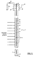
- an optical sensor string 3 includes optical sensor elements imbedded or formed within the core of an optical fiber 28 (Fig. 2) which is positioned within a capillary tube 5.
- fiber gratings Bragg gratings
- a measurand such as strain induced by pressure, will induce a perturbation of the grating sensor spacing due to overall fiber elongation, and of the refractive index of the glass due to photoelastic effects, which together change the wavelength of the light reflected by the grating.
- the value of the measurand is directly related to the wavelength reflected by the grating and can be determined by detecting the wavelength of the reflected light
- the wavelength encoded nature of the output of fiber gratings has advantages over intensity based sensing techniques because of the self-referencing nature of the output.
- This sensed information is encoded directly into the wavelength, which is an absolute parameter and does not depend upon total light levels, losses in fibers or couplers, or variations in source intensity.
- intensity-based sensing schemes depend upon total light levels and are affected by losses in the connected fibers, by losses in couplers, and by variations in source intensity.
- the optical sensor string 3 and capillary tubing 5 are interconnected to optical signal processing equipment 10 via well-known capillary tube delivery equipment (not shown) for delivering the optical sensor string 3 within the capillary tubing 5 down a wellbore 12 of an oil and/or gas well 13.
- the tubing delivery equipment provides for the delivery of the capillary tubing 5 and optical sensor string 3 down the wellbore 12, and for the delivery of optical signals between the optical signal processing equipment 10 and the optical sensor string 3 , either directly or via interface equipment (not shown) as required.
- the optical signal processing equipment 10 includes, at a minimum, a broadband source of light 11 , such as a light emitting diode (LED), and appropriate light filtering equipment for delivery of signal light to Bragg gratings included within the optical sensor string 3 , as described in greater detail below. Additionally, the optical signal processing equipment 10 includes appropriate optical signal analysis equipment 14 for analyzing the return signals from the Bragg gratings.
- the signal analysis equipment may include the necessary hardware and software to implement the optical signal diagnostic equipment disclosed in U.S. Patent Nos. 4,996,419; 5,401,956; 5,426,297; and/or 5,493,390, the disclosures of which are incorporated herein by reference.
- optical signal analysis approaches which may be utilized to analyze return signals from optical fiber Bragg gratings. These approaches may be generally classified in the following four categories:
- the particular technique utilized will vary, and will depend on the Bragg wavelength shift magnitude (which depends on the sensor sensitivity and measurand strength) and the frequency range of the measurand to be detected.
- the optical signal processing equipment may operate on a principle of wave-division multiplexing as described above wherein each bragg grating sensor is utilized at a different passband or frequency band of interest.
- the present invention may utilize time-division multiplexing for obtaining signals from multiple independent sensors, or any other suitable means for analyzing signals returned from a plurality of Bragg grating sensors formed in an fiber optic sensor string.
- the senor of the invention is utilized to measure pressure and/or temperature within the wellbore 12 of the oil and/or gas well 13 .
- casing strings 15 Within the wellbore 12 are casing strings 15 , production tubing 18 , and a production packers 20.
- the optical sensor string 3 is interconnected via appropriate optical fibers, couplers, etc., to the optical signal processing equipment 10 , which is located above the surface 20 of the wellbore 12 .
- the fiber optic sensor 6 of the invention includes an optical fiber 28 which is protected from mechanical damage and corrosive damage by placing it in the rigid wall capillary tube 5 .
- the capillary tubing 5 may be made of a high strength, corrosion resistant material, such as stainless steel.
- a distal end 32 of the tube 5 is sealed, for example, by welding on an end cap 37 .
- the distal end 32 of the tube 5 may be crimped and welded, or other suitable method may be utilized to hermetically seal the end of the tubing to prevent any material from the environment in which the tubing is placed from entering inside of the tubing where the optical fiber and fiber optic sensors are located.
- each Bragg grating 44 is constructed so as to reflect a particular wavelength or frequency of light which is propagating along the core, back in the direction of the light source from which it was launched. Each of the particular frequencies is different from the other such that each Bragg grating 44 reflects a unique frequency.
- the Bragg grating sensor string of the invention relies on a pressure fluctuation applied to the outside of the fiber, through the capillary tubing, to in turn generate a mechanical strain in the fiber core. Additionally, the sensor string relies on a change in the index of refraction, and to a lesser degree on mechanical strain, caused by thermal expansion/contraction, in response to temperature changes.
- the capillary tube 5 is filled with a high density, low compressibility material 48 .
- the high density, low compressibility material is a liquid, such as water, glycerine, or oil. It is also preferred that the high density, low compressibility material have a high thermal conductivity, such that temperature variations applied to the outside of the capillary tubing are rapidly and accurately transmitted to the Bragg gratings 44 located within the core 40 of the optical fiber 28 .
- the wall of the tube undergoes a radial displacement which increases or decreases the pressure of the high density, low compressibility material filling the capillary tube 5 .
- This pressure is in turn applied to the optical fiber 28 inside the high density, low compressibility material, thus generating a mechanical strain on the fiber 28 , which modulates the light being guided through the Bragg gratings 44 located within the fiber 28 .
- a sensor manufactured in accordance with the present invention has a very low acoustic transmission loss as compared to other devices in the prior art, such as prior art capillary tubes filled with a gas, either at low or high pressure.
- the advantages of the present invention are best understood by example.
- the following analysis was performed for two different capillary tubes having an outside diameter of 1 ⁇ 4 inch (0.635 cm).
- One capillary tube (TUBE 1) had a wall thickness of 0.047 inch (0.119 cm) and the other capillary tube (TUBE 2) had a wall thickness of 0.024 inch (0.061 cm).
- the following table illustrates the attenuation of an acoustic pressure signal of unit strength applied to the outside surface of the tubing.
- the acoustic signal was transmitted in water over a frequency range of approximately 50 hz to 2 Khz: TUBE AIR AT 1 ATM 1.01x10 5 n/m 2 AIR AT 100 ATM 1.01x10 7 n/m 2 AIR AT 200 ATM 2.03x10 7 n/m 2 Water Glycerin 1 3.5x10 -6 (109 dB) 3.5x10 -4 (69 dB) 7.0x10 -4 (63 dB) 0.006 (44 dB) 0.1 (20 dB) 2 6.5x10 -6 (104 db) 6.3x10 -4 (64 dB) 1.3x10 -3 (58 dB) 0.09 (21 dB) 0.2 (14 dB) As illustrated in the above table, for a capillary tube at one atmosphere of pressure, attenuation of an acoustic signal applied to the outside surface of the tubing causes an approximately 104dB or 109dB attenuation of the acoustic signal, i
- a much improved signal strength of a signal being detected by the sensor of the invention is provided. Additionally, by using a material having a high thermal conductivity, temperature variations in the environment in which the sensors are located are rapidly and accurately transmitted to the core 40 , such that the pressure signals may be accurately temperature compensated.
- the air has a thermal conductivity of approximately 0.025 w/m-°k.
- the high density, low compressibility materials such as oil, glycerine and water have thermal conductivity of approximately 0.15, 0.3 and 0.35, respectively.
- the high density, low compressibility material should have a thermal conductivity greater than approximately 0.1 w/m-°k. Therefore, these materials have substantially improved thermal conductivity and a shorter thermal time constant as compared to prior art air filled capillary tubes. Therefore, the system of the invention has a significantly shorter response time to thermal transients.
- the surface portion of the tube is provided with a reservoir for receiving excess fluid upon fluid expansion, and for providing fluid to maintain the capillary tubing filled with fluid.
- the reservoir may be a pressure controlled bellows structure 60 , as illustrated in Fig. 2.
- the bellows structure 60 includes an expansion tank or holding tank 61 to hold excess fluid 48 .
- a pressure source 62 such as high pressure air, may be provided to maintain the fluid 48 within the bellows structure 60 at a specified pressure, for example by providing a pressure regulator 65 to maintain a specified pressure within the holding tank 61 .
- the pressure within the bellows structure 60 may be controlled, for example by use of the regulator 65 , to maintain the fluid 48 in the liquid phase when exposed to high temperatures.
- means 68 are provided to allow the optical fiber 28 to pass through the bellows structure 60 while sealing the structure 60 to maintain the desired pressure. As will be understood by those skilled in the art, an excess length of optical fiber 68 is provided to allow expansion and contraction of the bellows structure 60 without damaging or applying excess tension to the optical fiber 28 .
- any suitable method of maintaining material 48 within the capillary tube 5 may be used.
- the invention may be provided with an overflow reservoir without pressure control. Additionally, if a solid material is utilized, such as a polymer, no overflow is required at all.
- the invention is described as using fiber Bragg gratings as sensors.
- the Bragg gratings are essentially described as point sensors.
- any suitable Bragg grating sensor configuration may be used.
- the Bragg gratings can be used for interferometric detection wherein a length of optical fiber is positioned between a pair of Bragg grating to thereby form a resonant cavity.
- the Bragg gratings may be used to form lazing elements for detection, for example by positioning an Ebrium doped length of optical fiber between a pair of Bragg gratings.
- the present invention will work equally as well with other types of sensors located within the capillary tubing.
- the benefits of the present invention are realized due to improved sensitivity of transmission of environmental pressure and temperature fluctuations to the sensors via the high density, low compressibility material.
- the invention is described as being used with a hermetically sealed tube to protect the optical fiber and sensors from the harsh environment.
- tube configurations may be used with the present invention, such as a "U" shaped tube, wherein both ends of the tube are above the surface of the borehole.
- the tube may be provided in any desired configuration in the borehole, such as wrapped around the drill string, to place sensors in a desired location within the borehole.
Landscapes
- Physics & Mathematics (AREA)
- General Physics & Mathematics (AREA)
- Optical Transform (AREA)
- Measuring Fluid Pressure (AREA)
- Measuring Temperature Or Quantity Of Heat (AREA)
- Length Measuring Devices By Optical Means (AREA)
- Examining Or Testing Airtightness (AREA)
- Investigating Or Analysing Materials By Optical Means (AREA)
Claims (24)
- Système de détection pour détecter un champ de mesurande dans un environnement, comprenant :dans lequel, ledit matériau est sensible à une force de compression exercée sur une surface externe dudit tube capillaire dans l'environnement pour fournir une force fluide et dans lequel lesdits éléments de détection sont sensibles à ladite force fluide et un signal lumineux pour chacun d'entre eux fournit un signal lumineux de détection indicatif de ladite force de compression.une structure de tube capillaire comprenant une matrice d'éléments de détection à fibres optiques intrinsèques couplées (44) constituée à l'intérieur d'une fibre optique (28), lesdits éléments de détection et ladite fibre optique étant déployés dans un tube capillaire (5), et ledit tube capillaire étant déployé dans l'environnement ; etun matériau de haute densité et de faible compressibilité (48) qui remplit complètement tous les espaces vides à l'intérieure de ladite structure de tube capillaire entre une surface interne dudit tube capillaire et ladite fibre optique, au moins dans une zone dudit tube capillaire contenant lesdits éléments de détection ;
- Système de détection selon la revendication 1, dans lequel chacun des éléments de détection est un diffuseur de Bragg (44) constitué dans le coeur de ladite fibre optique.
- Système de détection selon la revendication 1, dans lequel chacun desdits éléments de détection est un interféromètre comprenant un couple de diffuseurs de Bragg respectifs constitué dans le coeur de ladite fibre optique et une longueur de détection de la fibre optique située entre ledit couple de diffuseurs de Bragg.
- Système de détection selon la revendication 1, dans lequel chacun desdits éléments de détection est un élément laser comprenant un couple de diffuseurs de Bragg respectifs constitué dans le coeur de ladite fibre optique et une longueur de détection de la fibre optique dopée située entre ledit couple de diffuseurs de Bragg.
- Système de détection selon la revendication 1, dans lequel ladite structure de tube capillaire est hermétiquement close.
- Système de détection selon la revendication 1, dans lequel ledit matériau est sélectionné pour être thermoconducteur de manière à ce que la température dans l'environnement soit transmise rapidement et précisément au travers du tube capillaire et du matériau, à la fibre optique contenue dans celui-ci.
- Système de détection selon la revendication 6, dans lequel la conductivité thermique dudit matériau est supérieure à 0,1 w/m-°k.
- Système de détection selon la revendication 1, dans lequel, le matériau est un fluide.
- Système de détection selon la revendication 8, dans lequel le fluide est sélectionné dans le groupe constitué par l'eau, la glycérine et l'huile.
- Système de détection selon la revendication 8, comprenant en outre des moyens pour fournir un réservoir pour la dilatation et la contraction dudit fluide et pour maintenir ledit fluide à une pression spécifiée.
- Système de détection selon la revendication 1, dans lequel le matériau est un polymère.
- Système de détection selon la revendication 1, comprenant en outre une source optique (11) pour fournir ledit signal lumineux, ladite fibre optique étant interconnectée à ladite source optique.
- Système de détection selon la revendication 12, dans lequel la source optique est une diode électroluminescente.
- Système de détection selon la revendication 1, dans lequel le tube capillaire est fabriqué dans un matériau extrêmement résistant qui est imperméable à la pénétration des éléments dans l'environnement, ledit tube capillaire étant constitué d'un matériau transmettant la température, mais qui n'est que faiblement compressible et peut subir des forces de compression sans s'écraser.
- Système de détection selon la revendication 1, dans lequel ledit champ de mesurande est les fluctuations de pression acoustique dans un environnement, caractérisé par :dans lequel, les dits éléments de détection à fibres optiques intrinsèques sont une matrice de détecteurs à fibre optique intrinsèque couplée en série, lesdits détecteurs étant des diffuseurs de Bragg constitués dans un coeur de la fibre optique, ladite matrice étant interconnectée à ladite source optique par ladite fibre optique.une source optique fournissant ledit signal lumineux et
- Système de détection selon la revendication 15, dans lequel ladite structure de tube capillaire est hermétiquement close.
- Système de détection selon la revendication 15, dans lequel ledit matériau est sélectionné pour être thermoconducteur de manière à ce que la température dans l'environnement soit transmise rapidement et précisément au travers du tube capillaire et du matériau à la matrice.
- Système de détection selon la revendication 17, dans lequel la conductivité thermique dudit matériau est supérieure à 0,1 w/m-°k.
- Système de détection selon la revendication 15, dans lequel le matériau est un fluide.
- Système de détection selon la revendication 19, dans lequel le fluide est sélectionné dans le groupe constitué par l'eau, la glycérine et l'huile.
- Système de détection selon la revendication 19, comprenant en outre des moyens pour fournir un réservoir pour la dilatation et la contraction dudit fluide et pour maintenir ledit fluide à une pression spécifiée.
- Système de détection selon la revendication 15, dans lequel le matériau est un polymère.
- Système de détection selon la revendication 15, dans lequel la source optique est une diode électroluminescente.
- Système de détection selon la revendication 15, comprenant en outre des moyens de traitement de signal lumineux sensibles à chacun desdits signaux lumineux de détection respectifs pour fournir des signaux de pression acoustique indicatifs de variations de la pression acoustique dans l'environnement adjacent à chacun desdits éléments de détection respectifs.
Applications Claiming Priority (3)
| Application Number | Priority Date | Filing Date | Title |
|---|---|---|---|
| US777271 | 1996-12-31 | ||
| US08/777,271 US5767411A (en) | 1996-12-31 | 1996-12-31 | Apparatus for enhancing strain in intrinsic fiber optic sensors and packaging same for harsh environments |
| PCT/US1997/023980 WO1998029717A1 (fr) | 1996-12-31 | 1997-12-19 | Appareil permettant d'ameliorer la contrainte dans des detecteurs a fibres optiques intrinseques et de conditionner de tels detecteurs pour des environnements hostiles |
Publications (2)
| Publication Number | Publication Date |
|---|---|
| EP0950170A1 EP0950170A1 (fr) | 1999-10-20 |
| EP0950170B1 true EP0950170B1 (fr) | 2002-09-11 |
Family
ID=25109782
Family Applications (1)
| Application Number | Title | Priority Date | Filing Date |
|---|---|---|---|
| EP97953481A Expired - Lifetime EP0950170B1 (fr) | 1996-12-31 | 1997-12-19 | Appareil permettant d'ameliorer la contrainte dans des detecteurs a fibres optiques intrinseques et de conditionner de tels detecteurs pour des environnements hostiles |
Country Status (10)
| Country | Link |
|---|---|
| US (1) | US5767411A (fr) |
| EP (1) | EP0950170B1 (fr) |
| AR (1) | AR008552A1 (fr) |
| AU (1) | AU5722098A (fr) |
| CA (1) | CA2276449C (fr) |
| CO (1) | CO4771128A1 (fr) |
| DE (1) | DE69715455T2 (fr) |
| NO (1) | NO320490B1 (fr) |
| PE (1) | PE30599A1 (fr) |
| WO (1) | WO1998029717A1 (fr) |
Cited By (27)
| Publication number | Priority date | Publication date | Assignee | Title |
|---|---|---|---|---|
| US7490664B2 (en) | 2004-11-12 | 2009-02-17 | Halliburton Energy Services, Inc. | Drilling, perforating and formation analysis |
| US8424617B2 (en) | 2008-08-20 | 2013-04-23 | Foro Energy Inc. | Methods and apparatus for delivering high power laser energy to a surface |
| US8464794B2 (en) | 2009-06-29 | 2013-06-18 | Halliburton Energy Services, Inc. | Wellbore laser operations |
| US8571368B2 (en) | 2010-07-21 | 2013-10-29 | Foro Energy, Inc. | Optical fiber configurations for transmission of laser energy over great distances |
| US8627901B1 (en) | 2009-10-01 | 2014-01-14 | Foro Energy, Inc. | Laser bottom hole assembly |
| US8662160B2 (en) | 2008-08-20 | 2014-03-04 | Foro Energy Inc. | Systems and conveyance structures for high power long distance laser transmission |
| US8684088B2 (en) | 2011-02-24 | 2014-04-01 | Foro Energy, Inc. | Shear laser module and method of retrofitting and use |
| US8720584B2 (en) | 2011-02-24 | 2014-05-13 | Foro Energy, Inc. | Laser assisted system for controlling deep water drilling emergency situations |
| US8783360B2 (en) | 2011-02-24 | 2014-07-22 | Foro Energy, Inc. | Laser assisted riser disconnect and method of use |
| US8783361B2 (en) | 2011-02-24 | 2014-07-22 | Foro Energy, Inc. | Laser assisted blowout preventer and methods of use |
| US9027668B2 (en) | 2008-08-20 | 2015-05-12 | Foro Energy, Inc. | Control system for high power laser drilling workover and completion unit |
| US9074422B2 (en) | 2011-02-24 | 2015-07-07 | Foro Energy, Inc. | Electric motor for laser-mechanical drilling |
| US9080425B2 (en) | 2008-10-17 | 2015-07-14 | Foro Energy, Inc. | High power laser photo-conversion assemblies, apparatuses and methods of use |
| US9089928B2 (en) | 2008-08-20 | 2015-07-28 | Foro Energy, Inc. | Laser systems and methods for the removal of structures |
| US9138786B2 (en) | 2008-10-17 | 2015-09-22 | Foro Energy, Inc. | High power laser pipeline tool and methods of use |
| US9242309B2 (en) | 2012-03-01 | 2016-01-26 | Foro Energy Inc. | Total internal reflection laser tools and methods |
| US9244235B2 (en) | 2008-10-17 | 2016-01-26 | Foro Energy, Inc. | Systems and assemblies for transferring high power laser energy through a rotating junction |
| US9267330B2 (en) | 2008-08-20 | 2016-02-23 | Foro Energy, Inc. | Long distance high power optical laser fiber break detection and continuity monitoring systems and methods |
| US9347271B2 (en) | 2008-10-17 | 2016-05-24 | Foro Energy, Inc. | Optical fiber cable for transmission of high power laser energy over great distances |
| US9360643B2 (en) | 2011-06-03 | 2016-06-07 | Foro Energy, Inc. | Rugged passively cooled high power laser fiber optic connectors and methods of use |
| US9360631B2 (en) | 2008-08-20 | 2016-06-07 | Foro Energy, Inc. | Optics assembly for high power laser tools |
| US9562395B2 (en) | 2008-08-20 | 2017-02-07 | Foro Energy, Inc. | High power laser-mechanical drilling bit and methods of use |
| US9664012B2 (en) | 2008-08-20 | 2017-05-30 | Foro Energy, Inc. | High power laser decomissioning of multistring and damaged wells |
| US9669492B2 (en) | 2008-08-20 | 2017-06-06 | Foro Energy, Inc. | High power laser offshore decommissioning tool, system and methods of use |
| US9719302B2 (en) | 2008-08-20 | 2017-08-01 | Foro Energy, Inc. | High power laser perforating and laser fracturing tools and methods of use |
| US9845652B2 (en) | 2011-02-24 | 2017-12-19 | Foro Energy, Inc. | Reduced mechanical energy well control systems and methods of use |
| CN108917830A (zh) * | 2018-06-19 | 2018-11-30 | 杭州市质量技术监督检测院 | 一种具有自感应功能的智能墙体 |
Families Citing this family (47)
| Publication number | Priority date | Publication date | Assignee | Title |
|---|---|---|---|---|
| US6072567A (en) * | 1997-02-12 | 2000-06-06 | Cidra Corporation | Vertical seismic profiling system having vertical seismic profiling optical signal processing equipment and fiber Bragg grafting optical sensors |
| US6074503A (en) | 1997-04-22 | 2000-06-13 | Cable Design Technologies, Inc. | Making enhanced data cable with cross-twist cabled core profile |
| US6787758B2 (en) * | 2001-02-06 | 2004-09-07 | Baker Hughes Incorporated | Wellbores utilizing fiber optic-based sensors and operating devices |
| US6016702A (en) * | 1997-09-08 | 2000-01-25 | Cidra Corporation | High sensitivity fiber optic pressure sensor for use in harsh environments |
| US6058226A (en) * | 1997-10-24 | 2000-05-02 | D-Star Technologies Llc | Optical fiber sensors, tunable filters and modulators using long-period gratings |
| US6522797B1 (en) | 1998-09-01 | 2003-02-18 | Input/Output, Inc. | Seismic optical acoustic recursive sensor system |
| JP4615726B2 (ja) | 1998-12-04 | 2011-01-19 | ウェザーフォード/ラム インコーポレーテッド | ブラッグ回折格子圧力センサ |
| CN1153054C (zh) | 1998-12-04 | 2004-06-09 | 塞德拉公司 | 布拉格光栅压力传感器 |
| US6528239B1 (en) * | 1999-01-15 | 2003-03-04 | Sabeus Photonics, Inc. | Method of forming a grating in a waveguide |
| US6222973B1 (en) | 1999-01-15 | 2001-04-24 | D-Star Technologies, Inc. | Fabrication of refractive index patterns in optical fibers having protective optical coatings |
| US6148925A (en) | 1999-02-12 | 2000-11-21 | Moore; Boyd B. | Method of making a conductive downhole wire line system |
| US6233746B1 (en) | 1999-03-22 | 2001-05-22 | Halliburton Energy Services, Inc. | Multiplexed fiber optic transducer for use in a well and method |
| FR2791768B1 (fr) * | 1999-04-01 | 2001-04-20 | Commissariat Energie Atomique | Extensometre a reseau de bragg et procede de fabrication de cet extensometre |
| DE19938978A1 (de) * | 1999-08-19 | 2001-02-22 | Abb Research Ltd | Faseroptischer Drucksensor |
| US6439055B1 (en) | 1999-11-15 | 2002-08-27 | Weatherford/Lamb, Inc. | Pressure sensor assembly structure to insulate a pressure sensing device from harsh environments |
| AU782553B2 (en) * | 2000-01-05 | 2005-08-11 | Baker Hughes Incorporated | Method of providing hydraulic/fiber conduits adjacent bottom hole assemblies for multi-step completions |
| US6626043B1 (en) * | 2000-01-31 | 2003-09-30 | Weatherford/Lamb, Inc. | Fluid diffusion resistant glass-encased fiber optic sensor |
| KR100368122B1 (ko) * | 2000-05-04 | 2003-01-15 | 병 호 이 | 반사대역폭이 외부 인가 스트레인에 따라 변하는 처핑된 광섬유 격자 센서 및 이를 이용한 스트레인 측정 장치 |
| US6601671B1 (en) | 2000-07-10 | 2003-08-05 | Weatherford/Lamb, Inc. | Method and apparatus for seismically surveying an earth formation in relation to a borehole |
| GB0021976D0 (en) * | 2000-09-07 | 2000-10-25 | Optomed As | Multi-parameter fiber optic probes |
| NO315762B1 (no) * | 2000-09-12 | 2003-10-20 | Optoplan As | Sand-detektor |
| US20040042703A1 (en) * | 2002-08-28 | 2004-03-04 | Deaton Thomas M. | Method and apparatus for sensing an environmental parameter in a wellbore |
| US6978832B2 (en) | 2002-09-09 | 2005-12-27 | Halliburton Energy Services, Inc. | Downhole sensing with fiber in the formation |
| US6847034B2 (en) * | 2002-09-09 | 2005-01-25 | Halliburton Energy Services, Inc. | Downhole sensing with fiber in exterior annulus |
| US6888972B2 (en) * | 2002-10-06 | 2005-05-03 | Weatherford/Lamb, Inc. | Multiple component sensor mechanism |
| US20040065437A1 (en) * | 2002-10-06 | 2004-04-08 | Weatherford/Lamb Inc. | In-well seismic sensor casing coupling using natural forces in wells |
| GB2396211B (en) | 2002-10-06 | 2006-02-22 | Weatherford Lamb | Multiple component sensor mechanism |
| US7036601B2 (en) | 2002-10-06 | 2006-05-02 | Weatherford/Lamb, Inc. | Apparatus and method for transporting, deploying, and retrieving arrays having nodes interconnected by sections of cable |
| US7219729B2 (en) * | 2002-11-05 | 2007-05-22 | Weatherford/Lamb, Inc. | Permanent downhole deployment of optical sensors |
| US6915686B2 (en) | 2003-02-11 | 2005-07-12 | Optoplan A.S. | Downhole sub for instrumentation |
| US7159653B2 (en) | 2003-02-27 | 2007-01-09 | Weatherford/Lamb, Inc. | Spacer sub |
| US6957574B2 (en) * | 2003-05-19 | 2005-10-25 | Weatherford/Lamb, Inc. | Well integrity monitoring system |
| US6840114B2 (en) * | 2003-05-19 | 2005-01-11 | Weatherford/Lamb, Inc. | Housing on the exterior of a well casing for optical fiber sensors |
| US7397976B2 (en) * | 2005-01-25 | 2008-07-08 | Vetco Gray Controls Limited | Fiber optic sensor and sensing system for hydrocarbon flow |
| US8186428B2 (en) * | 2007-04-03 | 2012-05-29 | Baker Hughes Incorporated | Fiber support arrangement for a downhole tool and method |
| US7912334B2 (en) * | 2007-09-19 | 2011-03-22 | General Electric Company | Harsh environment temperature sensing system and method |
| WO2011012406A1 (fr) * | 2009-07-30 | 2011-02-03 | Hottinger Baldwin Messtechnik Gmbh | Dispositif et procédé de détection en résolution locale de mouvements de terrain |
| US8662165B2 (en) | 2010-07-06 | 2014-03-04 | Baker Hughes Incorporated | Fiber support arrangement and method |
| US8542955B2 (en) * | 2010-10-28 | 2013-09-24 | General Electric Company | Gas detection system incorporating fiber gas sensors having fiber bragg gratings |
| US20140327919A1 (en) * | 2013-05-06 | 2014-11-06 | Halliburton Energy Services. Inc. | Remote Seal for Pressure Sensor |
| CN103953330B (zh) * | 2014-04-02 | 2016-09-14 | 北京博简复才技术咨询有限公司 | 深井油气层温度与压力在线集成监测装置及方法 |
| US9624763B2 (en) | 2014-09-29 | 2017-04-18 | Baker Hughes Incorporated | Downhole health monitoring system and method |
| US9448312B1 (en) | 2015-03-11 | 2016-09-20 | Baker Hughes Incorporated | Downhole fiber optic sensors with downhole optical interrogator |
| NL2015952B1 (en) * | 2015-12-11 | 2017-07-03 | Fugro Tech Bv | Pressure sensor and sensor system comprising one or more pressure sensors. |
| CN105725982A (zh) * | 2016-01-25 | 2016-07-06 | 东华大学 | 一种基于光纤传感技术的鞋底温度、压力测试鞋垫 |
| US20200152354A1 (en) * | 2018-11-14 | 2020-05-14 | Minnesota Wire | Integrated circuits in cable |
| CN114252649B (zh) * | 2021-12-30 | 2024-08-23 | 中北大学 | 一种光纤流体流速探测装置 |
Family Cites Families (30)
| Publication number | Priority date | Publication date | Assignee | Title |
|---|---|---|---|---|
| US4235113A (en) * | 1978-08-21 | 1980-11-25 | Carome Edward F | Optical fiber acoustical sensors |
| EP0066493A1 (fr) * | 1981-05-15 | 1982-12-08 | Schlumberger Limited | Câble à fibre optique transducteur d'ondes de pression |
| US5363463A (en) * | 1982-08-06 | 1994-11-08 | Kleinerman Marcos Y | Remote sensing of physical variables with fiber optic systems |
| US4547869A (en) * | 1983-04-04 | 1985-10-15 | Western Geophysical Company Of America | Marine seismic sensor |
| US5625605A (en) * | 1983-09-13 | 1997-04-29 | The United States Of America As Represented By The Secretary Of The Navy | Optic bundle towed array |
| US5574699A (en) * | 1983-10-31 | 1996-11-12 | Cuomo; Frank W. | Fiber optic lever towed array |
| US4761073A (en) * | 1984-08-13 | 1988-08-02 | United Technologies Corporation | Distributed, spatially resolving optical fiber strain gauge |
| US4589285A (en) * | 1984-11-05 | 1986-05-20 | Western Geophysical Co. Of America | Wavelength-division-multiplexed receiver array for vertical seismic profiling |
| EP0241530B1 (fr) * | 1985-10-21 | 1990-05-02 | Plessey Overseas Limited | Systeme de detection utilisant des capteurs a fibres optiques |
| US4649529A (en) * | 1985-12-02 | 1987-03-10 | Exxon Production Research Co. | Multi-channel fiber optic sensor system |
| US4722603A (en) * | 1986-06-27 | 1988-02-02 | Chevron Research Company | Interferometric means and method for accurate determination of fiber-optic well logging cable length |
| US5163321A (en) * | 1989-10-17 | 1992-11-17 | Baroid Technology, Inc. | Borehole pressure and temperature measurement system |
| US4996419A (en) * | 1989-12-26 | 1991-02-26 | United Technologies Corporation | Distributed multiplexed optical fiber Bragg grating sensor arrangeement |
| US5227857A (en) * | 1991-04-24 | 1993-07-13 | The United States Of America As Represented By The Secretary Of The Navy | System for cancelling phase noise in an interferometric fiber optic sensor arrangement |
| US5485745A (en) * | 1991-05-20 | 1996-01-23 | Halliburton Company | Modular downhole inspection system for coiled tubing |
| US5275038A (en) * | 1991-05-20 | 1994-01-04 | Otis Engineering Corporation | Downhole reeled tubing inspection system with fiberoptic cable |
| US5397891A (en) * | 1992-10-20 | 1995-03-14 | Mcdonnell Douglas Corporation | Sensor systems employing optical fiber gratings |
| US5380995A (en) * | 1992-10-20 | 1995-01-10 | Mcdonnell Douglas Corporation | Fiber optic grating sensor systems for sensing environmental effects |
| US5361130A (en) * | 1992-11-04 | 1994-11-01 | The United States Of America As Represented By The Secretary Of The Navy | Fiber grating-based sensing system with interferometric wavelength-shift detection |
| EP0747570A1 (fr) * | 1992-12-07 | 1996-12-11 | Akishima Laboratories (Mitsui Zosen) Inc. | Vanne d'impulsion de pression pour système de mesure pendant le forage |
| KR960007884B1 (ko) * | 1993-04-24 | 1996-06-15 | 국방과학연구소 | 광섬유 격자를 이용한 광섬유소자 |
| IT1262407B (it) * | 1993-09-06 | 1996-06-19 | Finmeccanica Spa | Strumentazione utilizzante componenti in ottica integrata per la diagnostica di parti con sensori a fibra ottica inclusi o fissati sulla superficie. |
| US5426297A (en) * | 1993-09-27 | 1995-06-20 | United Technologies Corporation | Multiplexed Bragg grating sensors |
| US5401956A (en) * | 1993-09-29 | 1995-03-28 | United Technologies Corporation | Diagnostic system for fiber grating sensors |
| US5400427A (en) * | 1993-10-18 | 1995-03-21 | Mobil Oil Corporation | Fiber optic cable and viscous filler material |
| DE4337402A1 (de) * | 1993-10-26 | 1995-04-27 | Mannesmann Ag | Sonde zur Messung von Druck- und Temperaturprofilen |
| US5410404A (en) * | 1993-11-30 | 1995-04-25 | The United States Of America As Represented By The Secretary Of The Navy | Fiber grating-based detection system for wavelength encoded fiber sensors |
| US5451772A (en) * | 1994-01-13 | 1995-09-19 | Mechanical Technology Incorporated | Distributed fiber optic sensor |
| US5493113A (en) * | 1994-11-29 | 1996-02-20 | United Technologies Corporation | Highly sensitive optical fiber cavity coating removal detection |
| US5675674A (en) * | 1995-08-24 | 1997-10-07 | Rockbit International | Optical fiber modulation and demodulation system |
-
1996
- 1996-12-31 US US08/777,271 patent/US5767411A/en not_active Expired - Lifetime
-
1997
- 1997-12-19 AU AU57220/98A patent/AU5722098A/en not_active Abandoned
- 1997-12-19 CA CA002276449A patent/CA2276449C/fr not_active Expired - Fee Related
- 1997-12-19 DE DE69715455T patent/DE69715455T2/de not_active Expired - Lifetime
- 1997-12-19 WO PCT/US1997/023980 patent/WO1998029717A1/fr active IP Right Grant
- 1997-12-19 EP EP97953481A patent/EP0950170B1/fr not_active Expired - Lifetime
- 1997-12-23 CO CO97074671A patent/CO4771128A1/es unknown
- 1997-12-24 PE PE1997001164A patent/PE30599A1/es not_active Application Discontinuation
- 1997-12-30 AR ARP970106278A patent/AR008552A1/es unknown
-
1999
- 1999-06-29 NO NO993222A patent/NO320490B1/no not_active IP Right Cessation
Cited By (47)
| Publication number | Priority date | Publication date | Assignee | Title |
|---|---|---|---|---|
| US7490664B2 (en) | 2004-11-12 | 2009-02-17 | Halliburton Energy Services, Inc. | Drilling, perforating and formation analysis |
| US7938175B2 (en) | 2004-11-12 | 2011-05-10 | Halliburton Energy Services Inc. | Drilling, perforating and formation analysis |
| US9284783B1 (en) | 2008-08-20 | 2016-03-15 | Foro Energy, Inc. | High power laser energy distribution patterns, apparatus and methods for creating wells |
| US10036232B2 (en) | 2008-08-20 | 2018-07-31 | Foro Energy | Systems and conveyance structures for high power long distance laser transmission |
| US8511401B2 (en) | 2008-08-20 | 2013-08-20 | Foro Energy, Inc. | Method and apparatus for delivering high power laser energy over long distances |
| US8997894B2 (en) | 2008-08-20 | 2015-04-07 | Foro Energy, Inc. | Method and apparatus for delivering high power laser energy over long distances |
| US9027668B2 (en) | 2008-08-20 | 2015-05-12 | Foro Energy, Inc. | Control system for high power laser drilling workover and completion unit |
| US9719302B2 (en) | 2008-08-20 | 2017-08-01 | Foro Energy, Inc. | High power laser perforating and laser fracturing tools and methods of use |
| US9669492B2 (en) | 2008-08-20 | 2017-06-06 | Foro Energy, Inc. | High power laser offshore decommissioning tool, system and methods of use |
| US9664012B2 (en) | 2008-08-20 | 2017-05-30 | Foro Energy, Inc. | High power laser decomissioning of multistring and damaged wells |
| US8636085B2 (en) | 2008-08-20 | 2014-01-28 | Foro Energy, Inc. | Methods and apparatus for removal and control of material in laser drilling of a borehole |
| US8662160B2 (en) | 2008-08-20 | 2014-03-04 | Foro Energy Inc. | Systems and conveyance structures for high power long distance laser transmission |
| US9562395B2 (en) | 2008-08-20 | 2017-02-07 | Foro Energy, Inc. | High power laser-mechanical drilling bit and methods of use |
| US9360631B2 (en) | 2008-08-20 | 2016-06-07 | Foro Energy, Inc. | Optics assembly for high power laser tools |
| US8701794B2 (en) | 2008-08-20 | 2014-04-22 | Foro Energy, Inc. | High power laser perforating tools and systems |
| US8424617B2 (en) | 2008-08-20 | 2013-04-23 | Foro Energy Inc. | Methods and apparatus for delivering high power laser energy to a surface |
| US8757292B2 (en) | 2008-08-20 | 2014-06-24 | Foro Energy, Inc. | Methods for enhancing the efficiency of creating a borehole using high power laser systems |
| US9267330B2 (en) | 2008-08-20 | 2016-02-23 | Foro Energy, Inc. | Long distance high power optical laser fiber break detection and continuity monitoring systems and methods |
| US9089928B2 (en) | 2008-08-20 | 2015-07-28 | Foro Energy, Inc. | Laser systems and methods for the removal of structures |
| US8820434B2 (en) | 2008-08-20 | 2014-09-02 | Foro Energy, Inc. | Apparatus for advancing a wellbore using high power laser energy |
| US8826973B2 (en) | 2008-08-20 | 2014-09-09 | Foro Energy, Inc. | Method and system for advancement of a borehole using a high power laser |
| US8869914B2 (en) | 2008-08-20 | 2014-10-28 | Foro Energy, Inc. | High power laser workover and completion tools and systems |
| US8936108B2 (en) | 2008-08-20 | 2015-01-20 | Foro Energy, Inc. | High power laser downhole cutting tools and systems |
| US9327810B2 (en) | 2008-10-17 | 2016-05-03 | Foro Energy, Inc. | High power laser ROV systems and methods for treating subsea structures |
| US9080425B2 (en) | 2008-10-17 | 2015-07-14 | Foro Energy, Inc. | High power laser photo-conversion assemblies, apparatuses and methods of use |
| US9347271B2 (en) | 2008-10-17 | 2016-05-24 | Foro Energy, Inc. | Optical fiber cable for transmission of high power laser energy over great distances |
| US9244235B2 (en) | 2008-10-17 | 2016-01-26 | Foro Energy, Inc. | Systems and assemblies for transferring high power laser energy through a rotating junction |
| US9138786B2 (en) | 2008-10-17 | 2015-09-22 | Foro Energy, Inc. | High power laser pipeline tool and methods of use |
| US8528643B2 (en) | 2009-06-29 | 2013-09-10 | Halliburton Energy Services, Inc. | Wellbore laser operations |
| US8534357B2 (en) | 2009-06-29 | 2013-09-17 | Halliburton Energy Services, Inc. | Wellbore laser operations |
| US8464794B2 (en) | 2009-06-29 | 2013-06-18 | Halliburton Energy Services, Inc. | Wellbore laser operations |
| US8540026B2 (en) | 2009-06-29 | 2013-09-24 | Halliburton Energy Services, Inc. | Wellbore laser operations |
| US8678087B2 (en) | 2009-06-29 | 2014-03-25 | Halliburton Energy Services, Inc. | Wellbore laser operations |
| US8627901B1 (en) | 2009-10-01 | 2014-01-14 | Foro Energy, Inc. | Laser bottom hole assembly |
| US8571368B2 (en) | 2010-07-21 | 2013-10-29 | Foro Energy, Inc. | Optical fiber configurations for transmission of laser energy over great distances |
| US8879876B2 (en) | 2010-07-21 | 2014-11-04 | Foro Energy, Inc. | Optical fiber configurations for transmission of laser energy over great distances |
| US9074422B2 (en) | 2011-02-24 | 2015-07-07 | Foro Energy, Inc. | Electric motor for laser-mechanical drilling |
| US8720584B2 (en) | 2011-02-24 | 2014-05-13 | Foro Energy, Inc. | Laser assisted system for controlling deep water drilling emergency situations |
| US8684088B2 (en) | 2011-02-24 | 2014-04-01 | Foro Energy, Inc. | Shear laser module and method of retrofitting and use |
| US8783360B2 (en) | 2011-02-24 | 2014-07-22 | Foro Energy, Inc. | Laser assisted riser disconnect and method of use |
| US8783361B2 (en) | 2011-02-24 | 2014-07-22 | Foro Energy, Inc. | Laser assisted blowout preventer and methods of use |
| US9784037B2 (en) | 2011-02-24 | 2017-10-10 | Daryl L. Grubb | Electric motor for laser-mechanical drilling |
| US9845652B2 (en) | 2011-02-24 | 2017-12-19 | Foro Energy, Inc. | Reduced mechanical energy well control systems and methods of use |
| US9291017B2 (en) | 2011-02-24 | 2016-03-22 | Foro Energy, Inc. | Laser assisted system for controlling deep water drilling emergency situations |
| US9360643B2 (en) | 2011-06-03 | 2016-06-07 | Foro Energy, Inc. | Rugged passively cooled high power laser fiber optic connectors and methods of use |
| US9242309B2 (en) | 2012-03-01 | 2016-01-26 | Foro Energy Inc. | Total internal reflection laser tools and methods |
| CN108917830A (zh) * | 2018-06-19 | 2018-11-30 | 杭州市质量技术监督检测院 | 一种具有自感应功能的智能墙体 |
Also Published As
| Publication number | Publication date |
|---|---|
| AR008552A1 (es) | 2000-01-19 |
| US5767411A (en) | 1998-06-16 |
| NO320490B1 (no) | 2005-12-12 |
| NO993222L (no) | 1999-06-29 |
| NO993222D0 (no) | 1999-06-29 |
| DE69715455D1 (de) | 2002-10-17 |
| DE69715455T2 (de) | 2003-05-28 |
| PE30599A1 (es) | 1999-03-19 |
| CA2276449C (fr) | 2007-07-03 |
| AU5722098A (en) | 1998-07-31 |
| CA2276449A1 (fr) | 1998-07-09 |
| EP0950170A1 (fr) | 1999-10-20 |
| WO1998029717A1 (fr) | 1998-07-09 |
| CO4771128A1 (es) | 1999-04-30 |
Similar Documents
| Publication | Publication Date | Title |
|---|---|---|
| EP0950170B1 (fr) | Appareil permettant d'ameliorer la contrainte dans des detecteurs a fibres optiques intrinseques et de conditionner de tels detecteurs pour des environnements hostiles | |
| US8805128B2 (en) | Multi-point pressure sensor and uses thereof | |
| US6191414B1 (en) | Composite form as a component for a pressure transducer | |
| US5892860A (en) | Multi-parameter fiber optic sensor for use in harsh environments | |
| US5925879A (en) | Oil and gas well packer having fiber optic Bragg Grating sensors for downhole insitu inflation monitoring | |
| US5844667A (en) | Fiber optic pressure sensor with passive temperature compensation | |
| EP1012553B1 (fr) | Manometre a fibre optique de haute sensibilite pour environnements difficiles | |
| US7437027B2 (en) | Isolated sensor housing | |
| US6854327B2 (en) | Apparatus and method for monitoring compaction | |
| US6246048B1 (en) | Methods and apparatus for mechanically enhancing the sensitivity of longitudinally loaded fiber optic sensors | |
| US6072567A (en) | Vertical seismic profiling system having vertical seismic profiling optical signal processing equipment and fiber Bragg grafting optical sensors | |
| CA2461437C (fr) | Hydrophone a pression compensee | |
| US5118931A (en) | Fiber optic microbending sensor arrays including microbend sensors sensitive over different bands of wavelengths of light | |
| US6218661B1 (en) | Methods and apparatus for mechanically enhancing the sensitivity of transversely loaded fiber optic sensors | |
| CA2237197C (fr) | Dispositif de detection | |
| EP0922207A1 (fr) | Manometre a tube bourdon muni d'un capteur optique extensometrique integre destine a mesurer la deformation par traction ou par compression | |
| Yamate | Thermally insensitive pressure measurements up to 300 degree C using fiber Bragg gratings written onto side hole single mode fiber | |
| WO2000003217A2 (fr) | Forme composite utile en tant que composant pour un capteur de pression | |
| Udd | Thermally Insensitive Pressure Measurements up to 300 degree C Using Fiber Bragg Gratings Written onto Side Hole Single Mode Fiber Tsutomu Yamate, Rogerio T. Ramos and Robert J. Schroeder Schlumberger-Doll Research | |
| Lopez-Higuera et al. | Temperature, displacement, and acceleration fiber optic sensor for large machinery monitoring | |
| Kersey et al. | MONITORING TECHNIQUES |
Legal Events
| Date | Code | Title | Description |
|---|---|---|---|
| PUAI | Public reference made under article 153(3) epc to a published international application that has entered the european phase |
Free format text: ORIGINAL CODE: 0009012 |
|
| 17P | Request for examination filed |
Effective date: 19990721 |
|
| AK | Designated contracting states |
Kind code of ref document: A1 Designated state(s): DE FR GB |
|
| GRAG | Despatch of communication of intention to grant |
Free format text: ORIGINAL CODE: EPIDOS AGRA |
|
| 17Q | First examination report despatched |
Effective date: 20010823 |
|
| GRAG | Despatch of communication of intention to grant |
Free format text: ORIGINAL CODE: EPIDOS AGRA |
|
| GRAH | Despatch of communication of intention to grant a patent |
Free format text: ORIGINAL CODE: EPIDOS IGRA |
|
| GRAH | Despatch of communication of intention to grant a patent |
Free format text: ORIGINAL CODE: EPIDOS IGRA |
|
| RAP1 | Party data changed (applicant data changed or rights of an application transferred) |
Owner name: WEATHERFORD/LAMB, INC. |
|
| GRAA | (expected) grant |
Free format text: ORIGINAL CODE: 0009210 |
|
| AK | Designated contracting states |
Kind code of ref document: B1 Designated state(s): DE FR GB |
|
| REG | Reference to a national code |
Ref country code: GB Ref legal event code: FG4D |
|
| REF | Corresponds to: |
Ref document number: 69715455 Country of ref document: DE Date of ref document: 20021017 |
|
| ET | Fr: translation filed | ||
| PLBE | No opposition filed within time limit |
Free format text: ORIGINAL CODE: 0009261 |
|
| STAA | Information on the status of an ep patent application or granted ep patent |
Free format text: STATUS: NO OPPOSITION FILED WITHIN TIME LIMIT |
|
| 26N | No opposition filed |
Effective date: 20030612 |
|
| REG | Reference to a national code |
Ref country code: DE Ref legal event code: R081 Ref document number: 69715455 Country of ref document: DE Owner name: WEATHERFORD TECHNOLOGY HOLDINGS, LLC, HOUSTON, US Free format text: FORMER OWNER: WEATHERFORD/LAMB, INC., HOUSTON, TEX., US Effective date: 20150417 |
|
| REG | Reference to a national code |
Ref country code: FR Ref legal event code: TP Owner name: WEATHERFORD TECHNOLOGY HOLDINGS, LLC, US Effective date: 20150603 |
|
| REG | Reference to a national code |
Ref country code: FR Ref legal event code: PLFP Year of fee payment: 19 |
|
| REG | Reference to a national code |
Ref country code: GB Ref legal event code: 732E Free format text: REGISTERED BETWEEN 20151022 AND 20151028 |
|
| PGFP | Annual fee paid to national office [announced via postgrant information from national office to epo] |
Ref country code: DE Payment date: 20151215 Year of fee payment: 19 Ref country code: GB Payment date: 20151216 Year of fee payment: 19 |
|
| PGFP | Annual fee paid to national office [announced via postgrant information from national office to epo] |
Ref country code: FR Payment date: 20151110 Year of fee payment: 19 |
|
| REG | Reference to a national code |
Ref country code: DE Ref legal event code: R119 Ref document number: 69715455 Country of ref document: DE |
|
| GBPC | Gb: european patent ceased through non-payment of renewal fee |
Effective date: 20161219 |
|
| REG | Reference to a national code |
Ref country code: FR Ref legal event code: ST Effective date: 20170831 |
|
| PG25 | Lapsed in a contracting state [announced via postgrant information from national office to epo] |
Ref country code: FR Free format text: LAPSE BECAUSE OF NON-PAYMENT OF DUE FEES Effective date: 20170102 |
|
| PG25 | Lapsed in a contracting state [announced via postgrant information from national office to epo] |
Ref country code: DE Free format text: LAPSE BECAUSE OF NON-PAYMENT OF DUE FEES Effective date: 20170701 Ref country code: GB Free format text: LAPSE BECAUSE OF NON-PAYMENT OF DUE FEES Effective date: 20161219 |