EP0950140B1 - Drain water system - Google Patents
Drain water system Download PDFInfo
- Publication number
- EP0950140B1 EP0950140B1 EP97951388A EP97951388A EP0950140B1 EP 0950140 B1 EP0950140 B1 EP 0950140B1 EP 97951388 A EP97951388 A EP 97951388A EP 97951388 A EP97951388 A EP 97951388A EP 0950140 B1 EP0950140 B1 EP 0950140B1
- Authority
- EP
- European Patent Office
- Prior art keywords
- drain water
- conduit
- main drain
- main
- water conduit
- Prior art date
- Legal status (The legal status is an assumption and is not a legal conclusion. Google has not performed a legal analysis and makes no representation as to the accuracy of the status listed.)
- Expired - Lifetime
Links
- XLYOFNOQVPJJNP-UHFFFAOYSA-N water Substances O XLYOFNOQVPJJNP-UHFFFAOYSA-N 0.000 title claims description 208
- 239000002352 surface water Substances 0.000 claims description 35
- 238000007599 discharging Methods 0.000 claims description 14
- 238000004891 communication Methods 0.000 claims description 11
- 238000011109 contamination Methods 0.000 description 10
- 238000000926 separation method Methods 0.000 description 7
- 239000010866 blackwater Substances 0.000 description 4
- 238000012986 modification Methods 0.000 description 2
- 230000004048 modification Effects 0.000 description 2
- 238000005086 pumping Methods 0.000 description 2
- 210000002700 urine Anatomy 0.000 description 2
- 230000008030 elimination Effects 0.000 description 1
- 238000003379 elimination reaction Methods 0.000 description 1
- 239000000203 mixture Substances 0.000 description 1
- 238000009418 renovation Methods 0.000 description 1
- 230000000630 rising effect Effects 0.000 description 1
- 239000010865 sewage Substances 0.000 description 1
Images
Classifications
-
- E—FIXED CONSTRUCTIONS
- E03—WATER SUPPLY; SEWERAGE
- E03F—SEWERS; CESSPOOLS
- E03F1/00—Methods, systems, or installations for draining-off sewage or storm water
-
- Y—GENERAL TAGGING OF NEW TECHNOLOGICAL DEVELOPMENTS; GENERAL TAGGING OF CROSS-SECTIONAL TECHNOLOGIES SPANNING OVER SEVERAL SECTIONS OF THE IPC; TECHNICAL SUBJECTS COVERED BY FORMER USPC CROSS-REFERENCE ART COLLECTIONS [XRACs] AND DIGESTS
- Y10—TECHNICAL SUBJECTS COVERED BY FORMER USPC
- Y10S—TECHNICAL SUBJECTS COVERED BY FORMER USPC CROSS-REFERENCE ART COLLECTIONS [XRACs] AND DIGESTS
- Y10S210/00—Liquid purification or separation
- Y10S210/918—Miscellaneous specific techniques
- Y10S210/921—Flow equalization or time controlled stages or cycles
-
- Y—GENERAL TAGGING OF NEW TECHNOLOGICAL DEVELOPMENTS; GENERAL TAGGING OF CROSS-SECTIONAL TECHNOLOGIES SPANNING OVER SEVERAL SECTIONS OF THE IPC; TECHNICAL SUBJECTS COVERED BY FORMER USPC CROSS-REFERENCE ART COLLECTIONS [XRACs] AND DIGESTS
- Y10—TECHNICAL SUBJECTS COVERED BY FORMER USPC
- Y10T—TECHNICAL SUBJECTS COVERED BY FORMER US CLASSIFICATION
- Y10T137/00—Fluid handling
- Y10T137/4673—Plural tanks or compartments with parallel flow
Definitions
- the present invention relates to a drain water system according to the preamble of the attached independent claim.
- a system of the above mentioned type is previously known from e.g. SE, B, 409 480, SE 389 881, SE 504 962, DE 2 726 527, DE 3 500 130 and FR 2 681 354.
- drain water contaminated to different degrees is divided and collected in different containers in such devices.
- So-called black water originating from toilets may therefor be collected in one container
- blue water from showers, washbasins, bathtubs and similar may be collected in another container
- so-called green water from sinks may be collected in yet another container.
- the containers must thereafter somehow be discharged for taking care of the separated drain water, wherein it is not possible to utilize the ordinary main drain water conduit for a plurality of buildings without stopping the separation and the whole point is thereby lost.
- US-A-4 136 010 shows how a division of drain water is carried out at the end of a conduit for conducting the drain water to different substations depending upon the character of the drain water. Accordingly, quite separate conduits are used for conducting drain water to the different substations.
- US-A-3 503 413 discloses an auxiliary sewage storage system in which valves control the flow out of a so called main drain water conduit.
- the object of the present invention is to provide a system of the type defined in the introduction, which enables an elimination of the above mentioned disadvantages of previously known such systems.
- a utilization of the main drain water conduit for transportation of the separated drain water is enabled by these different characteristics while maintaining the separation in the stations, such as purifying plants, to which the drain water arrives for being taken care of.
- the first drain water system section has at least three said parts and at least three said containers and the second drain water system section has at least three main drain water stations
- the adjusting apparatus is arranged to obtain discharging of drain water from one of said parts via the container in question in the main drain water conduit and to transport drain water therein to one of said main drain water stations at a time while simultaneously preventing discharging of drain water from the other parts in the main drain water conduit and preventing transport of drain water through the main drain water conduit to any of the main drain water stations associated with said other parts of the first system section.
- the same good separation of the drain water is in this way achieved at said stations as in the different buildings connected to the main drain water conduit, which is of course a great advantage.
- the adjusting apparatus comprises members for an adjustable opening and closing of the flow communication through said conduits between said containers and the main drain water conduit, and according to another preferred embodiment of the invention the adjusting apparatus comprises members for an adjustable opening and closing of the flow communication between the main drain water conduit and the respective main drain water station.
- Such members of the adjusting apparatus ensure a possibility of maintaining optimum separation of drain water with different contamination characters from said containers to the main drain water stations.
- the adjusting apparatus comprises a pump arranged in each of said first conduits between each container and the main drain water conduit, said pump being formed to pump the drain water of the containers in question to the main drain water conduit during the time periods when discharging of said container is intended to take place.
- each said first conduit between said containers and the main drain water conduit is provided with a non-return valve for preventing a drain water flow from the main drain water conduit up to the respective container through the respective conduit. It is advantageous to arrange such a non-return valve in each conduit, while there is otherwise a risk that drain water with different contamination characters are being mixed due to that "wrong" drain water rises in one of said conduits and besides any thinkable risk for flowing at any container from the back is in this way prevented.
- the invention comprises second conduits for connecting the main drain water conduit with means for receiving surface water, such as a street inlet or a surface water conduit, and members are.arranged for an adjustable opening and closing of these second conduits.
- Means are therefor advantageously arranged to guide the surface water transported in the main drain water conduit past the main drain water stations to the location, such as a lake, a stream or similar, where the surface water normally is being delivered by means of the surface water conduits in such a situation.
- said members associated with the second conduits are arranged to open the respective connection conduit by excess surface water in said means for receiving surface water, and that said members of the adjusting apparatus are arranged to simultaneously with such an opening close the flow communication between at least said first container and the main drain water conduit.
- the adjusting apparatus is arranged to prevent discharging of drain water from all said containers in the main drain water conduit during certain time periods. The already above discussed draining of the main drain water conduit is thereby enabled.
- the adjusting apparatus is formed to realize its adjustment with said time periods between predetermined times in the day. This is advantageous when drain water in general and drain water with different degrees of contamination typically is being mainly produced during certain times of the day. Thus, it is by means of such a design of the adjusting apparatus possible to discharge the respective container at the time when it is most preferable.
- the invention comprises members for measuring the flow passing by in at least one of said conduits between the container in question and the main drain water conduit.
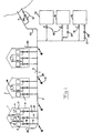
- FIG. 1 It is in fig 1 illustrated how three different buildings 1 are connected to a main drain water conduit 2 in common, there are however in practise normally more buildings connected to such a main drain water conduit, which is also indicated at 3.
- Each building has a first system section of the complete drain water system, which is divided into three parts in this case, which are arranged to receive drain water contaminated to different degrees from drain water receiving units, said parts leading to a container each for collecting drain water received from the respective units.
- First, second and third such parts with units 4, 5 and 6 respectively are only shown in the left building in the very schematical fig 1, and thereto connected first, second and third containers are indicated by the squares 7, 8 and 9 respectively.
- the respective first container 7 is thereby arranged to collect so-called "black" water, i.e.
- the containers 8 and 9 could be arranged for collecting "blue” and “green” water respectively according to the definitions above.
- Each container is connected to the main drain water conduit through a first conduit 10, 11, 12, which leads to three different stations 13, 14, 15 to take care of drain water of different qualities, and the intention is that the station 13 will take care of drain water originating from the first containers 7, the station 14 will take care of drain water from the second containers 8 and the station 15 will take care of drain water from the third containers 9.
- the system comprises further an adjusting apparatus comprising schematically illustrated members 16 for controlling a pump 17 arranged in each conduit to discharge a container of a certain type, a first, a second or a third, during certain time periods, in the main drain water conduit for all buildings, while the pumps belonging to other types of containers are kept turned off.
- the first conduits 10, 11 and 12 have further a non-return valve 18 each for preventing drain water flow from the main drain water conduit up to the respective container through the respective conduit.
- the system has also members 19 in the form of valves for an adjustable opening and closing of the flow communication between the main drain water conduit and the respective main drain water station in order to admit intake of drain water of the type, which is being transported in the main drain water conduit at a certain moment to the main drain water station intended for this drain water type.
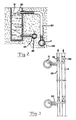
- the system comprises second conduits 20 for connecting the main drain water conduit 2 with means for receiving surface water, more exactly a surface water gutter 21 and indirectly with a surface water conduit 22, and members 23 are arranged for an adjustable opening and closing of these connection conduits. It is in fig 2 illustrated how a surface water gutter 21 has an overflow to the second conduit 20 so that surface water may be led to the main drain water conduit 2 at rising of the water level in the gutter 21 up to the overflow if the adjusting member 23 opens the communication to the main drain water conduit 2.
- the system has also pumps 24, 25 and 26 in return conduits from the second main drain water station 14, the third main drain water station 15 and the water course, from which the surface water is intended to be discharged, respectively for pumping water from these stations and from the water course into the main drain water conduit and the surface water conduit respectively for fire-fighting purposes.
- These return conduits have therefor valve members 27 for an optional closing and opening thereof.
- the main drain water conduit 2 and the surface water conduit 22 have arranged valve members 28 and 29 respectively downstream of the respective surface water gutter 21, said valve members may be closed when there is a desire for filling the respective surface water gutter with water for fire-fighting purposes.
- Use of the main drain water conduit is enabled in order to fight fires due to that it may be determined during which time periods different types of drain water is being transported in the main drain water conduit, since it is possible to arrange that only water of a quality acceptable for fighting fires is present in the drain water conduit when there is a desire for such fire-fighting, i.e. at least the communication between said first container 7 and the main drain water conduit through the first conduits 10 is closed.
- a member 31 for measuring the drain water volume passing through the respective conduit 10 is indicated in the left building for enabling debit of the released volume of the specific drain water quality.
- a plurality of possible modifications have already been touched upon earlier and it may here e.g. be added that it is of course within the scope of the invention to provide a plurality of main drain water conduits, to which different buildings are connected, and which may emerge in a common main drain water conduit, or a plurality of main drain water conduits could lead to one or each of the main drain water stations. It would also be possible to combine the device according to the invention with conventional drain water systems, so that there are drain water systems without any separation parallel to the device according to the invention, wherein it would be possible to lead such drain water to the main drain water station arranged to take care of the drain water contaminated to a high degree.
Landscapes
- Health & Medical Sciences (AREA)
- Life Sciences & Earth Sciences (AREA)
- Engineering & Computer Science (AREA)
- Hydrology & Water Resources (AREA)
- Public Health (AREA)
- Water Supply & Treatment (AREA)
- Sewage (AREA)
- Domestic Plumbing Installations (AREA)
- Sink And Installation For Waste Water (AREA)
Applications Claiming Priority (3)
| Application Number | Priority Date | Filing Date | Title |
|---|---|---|---|
| SE9604764A SE9604764L (sv) | 1996-12-20 | 1996-12-20 | Anordning vid ett avloppsystem samt ett förfarande för transport av avloppsvatten |
| SE9604764 | 1996-12-20 | ||
| PCT/SE1997/002148 WO1998028497A1 (en) | 1996-12-20 | 1997-12-18 | A device in a waste water system and a method for transporting waste water |
Publications (2)
| Publication Number | Publication Date |
|---|---|
| EP0950140A1 EP0950140A1 (en) | 1999-10-20 |
| EP0950140B1 true EP0950140B1 (en) | 2003-11-12 |
Family
ID=20405119
Family Applications (1)
| Application Number | Title | Priority Date | Filing Date |
|---|---|---|---|
| EP97951388A Expired - Lifetime EP0950140B1 (en) | 1996-12-20 | 1997-12-18 | Drain water system |
Country Status (9)
| Country | Link |
|---|---|
| US (1) | US6261443B1 (da) |
| EP (1) | EP0950140B1 (da) |
| AU (1) | AU5504298A (da) |
| CA (1) | CA2275597A1 (da) |
| DE (1) | DE69726183T2 (da) |
| DK (1) | DK0950140T3 (da) |
| ES (1) | ES2210590T3 (da) |
| SE (1) | SE9604764L (da) |
| WO (1) | WO1998028497A1 (da) |
Families Citing this family (5)
| Publication number | Priority date | Publication date | Assignee | Title |
|---|---|---|---|---|
| SE9800664L (sv) * | 1998-03-04 | 1999-08-23 | Split Vision Dev Ab | Anordning och förfarande vid ett avloppssystem där huvudavloppsledningen är utformad som en sluten ringledning |
| US7096885B2 (en) * | 2003-08-29 | 2006-08-29 | Renewability Energy Inc. | Non-pressurized flow-splitting water supply system |
| US20080175668A1 (en) * | 2007-01-18 | 2008-07-24 | Larry Wayne Haese | Graywater recycling system including rainwater recovery |
| EA201491806A1 (ru) * | 2009-06-16 | 2015-01-30 | Дек Дизайн Микэникл Кэнсалтентс Лтд. | Система энергоснабжения |
| US20130264294A1 (en) * | 2011-09-29 | 2013-10-10 | James Andrew McDermott | Building Air Conditioner Evaporator Condensation Management System |
Family Cites Families (13)
| Publication number | Priority date | Publication date | Assignee | Title |
|---|---|---|---|---|
| US3503413A (en) | 1967-05-03 | 1970-03-31 | Aerojet General Co | Auxiliary sewage storage system for temporarily storing sewage |
| SE389881B (sv) | 1975-04-16 | 1976-11-22 | Wennstroem E | Anordning vid avloppssystem |
| DE2726527A1 (de) * | 1977-06-11 | 1978-12-21 | Heike Klawe | Verfahren zur einsparung von trinkwasser vorzugsweise in haushaltungen und eine anlage zur durchfuehrung des verfahrens |
| SE409480B (sv) * | 1977-12-14 | 1979-08-20 | Electrolux Ab | Sett att transportera avloppsvatten medelst vakuum |
| US4136010A (en) * | 1978-04-05 | 1979-01-23 | Calspan Corporation | Catch basin interceptor |
| US4618421A (en) * | 1982-09-27 | 1986-10-21 | Kantor Frederick W | Fluid transport and processing system |
| US4465594A (en) * | 1982-09-29 | 1984-08-14 | Rein Laak | Sewage system for the treatment of segregated domestic waste water |
| DE3500130C2 (de) * | 1985-01-04 | 1995-11-09 | Wuelfing Bautraeger Gmbh | Wasserversorgungsanlage für die Toilettenspülung in Wohn- und/oder Geschäftsgebäuden |
| US4796311A (en) * | 1987-04-10 | 1989-01-10 | Jay Shankman | Chemical and/or radiation decontamination |
| US4744385A (en) * | 1987-08-27 | 1988-05-17 | Houghton William H | Water supply and waste removal system for a vehicle |
| FR2681354A1 (fr) * | 1991-09-12 | 1993-03-19 | Henry Eugene | Regeneration des eaux de bains en vue de leur utilisation dans les wc et l'arrosage des jardins. |
| US5575304A (en) * | 1995-04-13 | 1996-11-19 | Environmental Resources Management | Vacuum sewer system |
| SE504962C2 (sv) | 1995-11-01 | 1997-06-02 | Split Vision Dev Ab | Anordning vid ett avloppssystem i en byggnad för olika grader av förorenat avloppsvatten |
-
1996
- 1996-12-20 SE SE9604764A patent/SE9604764L/xx not_active IP Right Cessation
-
1997
- 1997-12-18 DE DE69726183T patent/DE69726183T2/de not_active Expired - Fee Related
- 1997-12-18 CA CA002275597A patent/CA2275597A1/en not_active Abandoned
- 1997-12-18 ES ES97951388T patent/ES2210590T3/es not_active Expired - Lifetime
- 1997-12-18 EP EP97951388A patent/EP0950140B1/en not_active Expired - Lifetime
- 1997-12-18 WO PCT/SE1997/002148 patent/WO1998028497A1/en not_active Ceased
- 1997-12-18 US US09/331,035 patent/US6261443B1/en not_active Expired - Fee Related
- 1997-12-18 AU AU55042/98A patent/AU5504298A/en not_active Abandoned
- 1997-12-18 DK DK97951388T patent/DK0950140T3/da active
Also Published As
| Publication number | Publication date |
|---|---|
| DE69726183T2 (de) | 2004-09-02 |
| DE69726183D1 (de) | 2003-12-18 |
| ES2210590T3 (es) | 2004-07-01 |
| SE506568C2 (sv) | 1998-01-12 |
| US6261443B1 (en) | 2001-07-17 |
| SE9604764L (sv) | 1998-01-12 |
| SE9604764D0 (sv) | 1996-12-20 |
| EP0950140A1 (en) | 1999-10-20 |
| AU5504298A (en) | 1998-07-17 |
| DK0950140T3 (da) | 2004-03-08 |
| WO1998028497A1 (en) | 1998-07-02 |
| CA2275597A1 (en) | 1998-07-02 |
Similar Documents
| Publication | Publication Date | Title |
|---|---|---|
| CN212561795U (zh) | 一种基于市政道路合流制管网的排水系统 | |
| CN210032029U (zh) | 与自然水体连通的管道的治理系统 | |
| JPS6140823B2 (da) | ||
| EP0950140B1 (en) | Drain water system | |
| ATE147029T1 (de) | Toilettenanlage | |
| CN212896712U (zh) | 一种基于市政道路分流制管网的排水系统 | |
| US20010047965A1 (en) | Wastewater treatment system and method | |
| CN111424791B (zh) | 具有雨污分流及调蓄机构的设备 | |
| GB1581677A (en) | Apparatus for conveying granular solids hydraulically | |
| CN209989914U (zh) | 一种一体化截污井 | |
| CN215403285U (zh) | 一种排水管道溢流污水处理系统 | |
| EP0287350A2 (en) | Vacuum sewage collecting system | |
| CN113023856A (zh) | 一种排水管道溢流污水处理系统及方法 | |
| DE2922868A1 (de) | Verfahren, apparaturen und gegenstaende zur nutzbarmachung von staubaren fluessigkeiten (auch traegerfluessigkeiten von feststoffen etc.) z.b. und insbesondere atmosphaerischem niederschlagswasser, unter ausnutzung von geo-energie | |
| CN212612879U (zh) | 具有雨污分流及调蓄机构的设备 | |
| RU2109649C1 (ru) | Туалетная система транспортного средства | |
| CN212896689U (zh) | 基于雨污分流的管网系统 | |
| CN208748795U (zh) | 一种切割式多通道污水排放装置 | |
| JP2002309660A (ja) | 下水処理水の送水システム | |
| Weller et al. | Diversion and Treatment of Extraneous Flows in Sanitary Sewers | |
| JPH09209432A (ja) | 雨水利用の便器洗浄水供給装置 | |
| EP1712526A1 (en) | Method and arrangement for wastewater purification | |
| AU750508B2 (en) | Sustainable water supply system for urban buildings | |
| AU771721B2 (en) | Wastewater treatment plant operating procedure | |
| US20060080766A1 (en) | Water saver adapter |
Legal Events
| Date | Code | Title | Description |
|---|---|---|---|
| PUAI | Public reference made under article 153(3) epc to a published international application that has entered the european phase |
Free format text: ORIGINAL CODE: 0009012 |
|
| 17P | Request for examination filed |
Effective date: 19990713 |
|
| AK | Designated contracting states |
Kind code of ref document: A1 Designated state(s): DE DK ES FI FR GB IT SE |
|
| RBV | Designated contracting states (corrected) |
Designated state(s): DE DK ES FI FR GB IT SE |
|
| 17Q | First examination report despatched |
Effective date: 20020619 |
|
| GRAH | Despatch of communication of intention to grant a patent |
Free format text: ORIGINAL CODE: EPIDOS IGRA |
|
| RTI1 | Title (correction) |
Free format text: DRAIN WATER SYSTEM |
|
| RTI1 | Title (correction) |
Free format text: DRAIN WATER SYSTEM |
|
| GRAS | Grant fee paid |
Free format text: ORIGINAL CODE: EPIDOSNIGR3 |
|
| GRAA | (expected) grant |
Free format text: ORIGINAL CODE: 0009210 |
|
| AK | Designated contracting states |
Kind code of ref document: B1 Designated state(s): DE DK ES FI FR GB IT SE |
|
| REG | Reference to a national code |
Ref country code: GB Ref legal event code: FG4D |
|
| REF | Corresponds to: |
Ref document number: 69726183 Country of ref document: DE Date of ref document: 20031218 Kind code of ref document: P |
|
| PG25 | Lapsed in a contracting state [announced via postgrant information from national office to epo] |
Ref country code: SE Free format text: LAPSE BECAUSE OF FAILURE TO SUBMIT A TRANSLATION OF THE DESCRIPTION OR TO PAY THE FEE WITHIN THE PRESCRIBED TIME-LIMIT Effective date: 20040212 |
|
| REG | Reference to a national code |
Ref country code: DK Ref legal event code: T3 |
|
| REG | Reference to a national code |
Ref country code: ES Ref legal event code: FG2A Ref document number: 2210590 Country of ref document: ES Kind code of ref document: T3 |
|
| ET | Fr: translation filed | ||
| PLBE | No opposition filed within time limit |
Free format text: ORIGINAL CODE: 0009261 |
|
| STAA | Information on the status of an ep patent application or granted ep patent |
Free format text: STATUS: NO OPPOSITION FILED WITHIN TIME LIMIT |
|
| 26N | No opposition filed |
Effective date: 20040813 |
|
| PGFP | Annual fee paid to national office [announced via postgrant information from national office to epo] |
Ref country code: FI Payment date: 20061227 Year of fee payment: 10 |
|
| PGFP | Annual fee paid to national office [announced via postgrant information from national office to epo] |
Ref country code: DK Payment date: 20061228 Year of fee payment: 10 |
|
| PGFP | Annual fee paid to national office [announced via postgrant information from national office to epo] |
Ref country code: GB Payment date: 20061229 Year of fee payment: 10 Ref country code: ES Payment date: 20061229 Year of fee payment: 10 |
|
| PGFP | Annual fee paid to national office [announced via postgrant information from national office to epo] |
Ref country code: IT Payment date: 20061231 Year of fee payment: 10 |
|
| PGFP | Annual fee paid to national office [announced via postgrant information from national office to epo] |
Ref country code: DE Payment date: 20070221 Year of fee payment: 10 |
|
| PGFP | Annual fee paid to national office [announced via postgrant information from national office to epo] |
Ref country code: FR Payment date: 20061229 Year of fee payment: 10 |
|
| PG25 | Lapsed in a contracting state [announced via postgrant information from national office to epo] |
Ref country code: FI Free format text: LAPSE BECAUSE OF NON-PAYMENT OF DUE FEES Effective date: 20071218 |
|
| REG | Reference to a national code |
Ref country code: DK Ref legal event code: EBP |
|
| GBPC | Gb: european patent ceased through non-payment of renewal fee |
Effective date: 20071218 |
|
| PG25 | Lapsed in a contracting state [announced via postgrant information from national office to epo] |
Ref country code: DE Free format text: LAPSE BECAUSE OF NON-PAYMENT OF DUE FEES Effective date: 20080701 |
|
| REG | Reference to a national code |
Ref country code: FR Ref legal event code: ST Effective date: 20081020 |
|
| PG25 | Lapsed in a contracting state [announced via postgrant information from national office to epo] |
Ref country code: GB Free format text: LAPSE BECAUSE OF NON-PAYMENT OF DUE FEES Effective date: 20071218 |
|
| PG25 | Lapsed in a contracting state [announced via postgrant information from national office to epo] |
Ref country code: DK Free format text: LAPSE BECAUSE OF NON-PAYMENT OF DUE FEES Effective date: 20080102 |
|
| REG | Reference to a national code |
Ref country code: ES Ref legal event code: FD2A Effective date: 20071219 |
|
| PG25 | Lapsed in a contracting state [announced via postgrant information from national office to epo] |
Ref country code: FR Free format text: LAPSE BECAUSE OF NON-PAYMENT OF DUE FEES Effective date: 20071231 Ref country code: ES Free format text: LAPSE BECAUSE OF NON-PAYMENT OF DUE FEES Effective date: 20071219 |
|
| PG25 | Lapsed in a contracting state [announced via postgrant information from national office to epo] |
Ref country code: IT Free format text: LAPSE BECAUSE OF NON-PAYMENT OF DUE FEES Effective date: 20071218 |