EP0949947B1 - Hochleistungsfiltrationssystem - Google Patents
Hochleistungsfiltrationssystem Download PDFInfo
- Publication number
- EP0949947B1 EP0949947B1 EP97950851A EP97950851A EP0949947B1 EP 0949947 B1 EP0949947 B1 EP 0949947B1 EP 97950851 A EP97950851 A EP 97950851A EP 97950851 A EP97950851 A EP 97950851A EP 0949947 B1 EP0949947 B1 EP 0949947B1
- Authority
- EP
- European Patent Office
- Prior art keywords
- filter
- filtration
- bed
- media
- wastewater
- Prior art date
- Legal status (The legal status is an assumption and is not a legal conclusion. Google has not performed a legal analysis and makes no representation as to the accuracy of the status listed.)
- Expired - Lifetime
Links
Images


Classifications
-
- B—PERFORMING OPERATIONS; TRANSPORTING
- B01—PHYSICAL OR CHEMICAL PROCESSES OR APPARATUS IN GENERAL
- B01D—SEPARATION
- B01D24/00—Filters comprising loose filtering material, i.e. filtering material without any binder between the individual particles or fibres thereof
- B01D24/02—Filters comprising loose filtering material, i.e. filtering material without any binder between the individual particles or fibres thereof with the filter bed stationary during the filtration
- B01D24/10—Filters comprising loose filtering material, i.e. filtering material without any binder between the individual particles or fibres thereof with the filter bed stationary during the filtration the filtering material being held in a closed container
- B01D24/12—Downward filtration, the filtering material being supported by pervious surfaces
-
- B—PERFORMING OPERATIONS; TRANSPORTING
- B01—PHYSICAL OR CHEMICAL PROCESSES OR APPARATUS IN GENERAL
- B01D—SEPARATION
- B01D24/00—Filters comprising loose filtering material, i.e. filtering material without any binder between the individual particles or fibres thereof
- B01D24/46—Regenerating the filtering material in the filter
- B01D24/4631—Counter-current flushing, e.g. by air
-
- B—PERFORMING OPERATIONS; TRANSPORTING
- B01—PHYSICAL OR CHEMICAL PROCESSES OR APPARATUS IN GENERAL
- B01D—SEPARATION
- B01D2201/00—Details relating to filtering apparatus
- B01D2201/18—Filters characterised by the openings or pores
- B01D2201/184—Special form, dimension of the openings, pores of the filtering elements
- B01D2201/186—Pore openings which can be modified
Definitions
- This invention relates to filtration systems, including filtration systems used in connection with tertiary treatment of wastewater for reduction of suspended solids.
- wastewater is disinfected by chlorination or ultraviolet irradiation where the treated wastewater is discharged to inland surface waters.
- Disinfection of this type typically achieves complete destruction of pathogenic bacteria and substantial deactivation of viruses, but does not provide complete virus destruction. Viruses have been detected in secondary effluents.
- Title 22 of the California Administrative Code is directed to tertiary treatment requirements. Viral monitoring is not specified in Title 22 because viruses typically occur in low concentrations in treated wastewater. Viral monitoring is expensive. Viral assays require special expertise. Laboratory procedures usually are off line and time consuming. Analytical costs are high. Therefore, instead of imposing measurements of viral concentrations, Title 22 sets forth a tertiary treatment system that consists of chemical coagulation, sedimentation, filtration, and disinfection where the public may be exposed to the treated wastewater, as in a recreational impoundment.
- turbidity of the treated effluent normally cannot exceed an average operating value of 2 NTU after final filtration, and cannot exceed 5 turbidity units more than 5 percent of the time during any 24 hour period. Chlorination after this level of treatment typically insures effective virus destruction sufficient for the protection of public health. Direct filtration with chemical addition is allowed as an alternative to the complete treatment systems specified in Title 22 where it has been demonstrated that the results of the two treatment systems are comparable and meet the appropriate criteria.
- Masuda et al. U.S. Patent No. 5,248,415 discloses an upward flow filtration apparatus that is said to be useful as a tertiary filter for wastewater treatment systems and to operate at a relatively high flow rate.
- An embodiment of the subject matter described in the Masuda patent is represented in Figure 24 generally at 28 and is labelled Prior Art.
- the filtration media described in the Masuda patent comprise a plurality of crimpy fibrous lumps.
- the fibrous lumps are disposed in the upward flow filtration apparatus 28 between first and second perforated panels 36 and 38 , respectively.
- the wastewater flows in an upward direction through the fibrous lumps and suspended matter is captured by the individual fibrous lumps.
- the first perforated panel 36 is immovably mounted within the apparatus and the second perforated panel 38 is movably mounted within the apparatus and spaced below the first perforated panel.
- the lower movable perforated panel 38 or bottom plate, is raised to compress the fibrous lumps to eliminate air gaps and to form a dense filter layer.
- the wastewater passes upwardly through the movable bottom plate and the filter layer and exits the top immovable plate 36 . Fine solid materials in the upward flow are said to progressively adhere to the filter layer from the lower portion to the upper portion thereof in that order. With progressive filtration, resistance to filtration is increased.
- the movable bottom plate is lowered from time to time and is said to define a cleaning chamber when the filtration performance is reduced and it becomes necessary to clean the fibrous lumps.
- a ram or screw 40 for moving the bottom plate passes through the wastewater, the media, and the top stationary plate 36 .
- the screw decreases the amount of room available for the media and potentially causes some channeling through the media in the region of the screw.
- the media are constructed of a loose fiber and can become entangled in the screw as it turns.
- a seal is used where the screw passes through the top plate, further complicating the operation of the device.
- the filter media is washed by moving the bottom plate downwardly away from the media to define a cleaning chamber.
- the flow rate of the wash water makes it difficult to achieve separation between the media and to obtain efficient cleaning.
- the Masuda device has typically required washing of the filter media on a frequent basis at a full flow rate of wash water equivalent to the flow rate of wastewater. Thus the overall efficiency of the apparatus described in the Masuda patent is greatly reduced.
- the invention provides a high rate filtration system in which the collector size and effective pore size of the filtration media can be adjusted according to influent conditions and to promote efficient cleaning of the media.
- the fluid travels through successive layers of filter media in which each layer becomes progressively more compressed with a smaller effective pore size and collector size for filtration and removes smaller and smaller particles.
- the compression gradient promotes more uniform loading of the media throughout the filter bed.
- the compression gradient can be altered during filtration to adjust head loss across the media and to extend the time for filtration while maintaining filtration efficiency within acceptable limits.
- effluent turbidity values of 2 NTU or lower can be achieved without chemical addition for influent turbidity values of up to approximately 8 NTU when the flow is from about 820 to 1230 L/m 2 •min (20 to 30 gal/ft 2 •min) at a bed compression ratio of from about 15 to 40 percent.
- the percentage of backwash water required at filtration rates of 820 and 1230 L/m 2 •min (20 to 30 gal/ft 2 •min) and at bed compression values of from 20 and 30 percent is from about 1 to 3 percent.
- the filtration system of the invention should be operable at increased flow rates above 1230 L/m 2 •min (30 gal/ft 2 •min) so long as the head loss across the filter does not result in uneconomical operation. Flow rates of 1640 L/m 2 •min (40 gal/ft 2 •min) to 2050 L/m 2 •min (50 gal/ft 2 •min) or more should be useful, depending on the results desired.
- the filtration apparatus of the invention is suitable for a wide variety of fluid/solid separations, including reducing suspended solids in municipal and industrial wastewater, recovery of machine shop working fluids, and a host of other separations.
- Compressible fibrous lump filter media as described in Mausda et al. U.S. Patent No. 5,248,415 are contained between upper and lower perforated panels in which, for operation in the upflow mode, the upper panel, or top plate, is movable to adjust the porosity and collector size of the media.
- a gradient of porosity is established across the filter bed in which the porosity is increased from top to bottom, which is opposite the direction of fluid flow.
- the fluid to be filtered enters filter media at the less compressed bottom in the upflow mode. Larger particles are trapped in the lower portion of the bed where the fluid enters. Smaller particles travel through to successive layers of filter media. The final upper layer of filtration media removes the smallest particles for which filtration is provided.
- the compressed layer of filter media at the top clogs less frequently than when the bottom layer of filter media is compressed because the top layer filters only the fines and not the large size particles in addition.
- the high rate filtration system of the invention typically is offstream less frequently and requires less washing of the media than prior apparatus. Filtration efficiency is comparable to that of other filters, but at filtration flow rates that typically are many times faster.
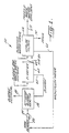
- FIG. 1 Represented in Figure 1 generally at 50 in highly schematic form is a representative activated sludge plant incorporating the filtration apparatus of the invention for tertiary treatment of raw municipal sewage for increased removal of suspended solids.
- the configuration of the activated sludge plant as represented is but one example of an activated sludge plant and that numerous alternatives are available.
- the invention is described in the context of a tertiary treatment system for municipal sewage that is treated by an activated sludge process, the invention described herein is not so limited.
- the invention is not limited to particular configurations or modes of operation of activated sludge plants, or to use in connection with an activated sludge plant.
- the filtration apparatus of the invention can be used to treat wastewater that is not subjected to sludge digestion. Where it is desired to use the wastewater for its nutrient content, as in fertilizer, then the wastewater may be subjected to primary clarification prior to filtering in an apparatus of the invention and in the absence of sludge digestion. The wastewater may be screened and subjected to a swirl separator to remove large non-suspended solids, including cups, rags, boards, and other trash, prior to filtering in an apparatus of the invention.
- the invention is not limited to the treatment of sewage or other municipal or industrial wastewater.
- the invention described herein should normally be useful in connection with a wide variety of filtration processes in which solids of appropriate particle size for the effective pore size of the media are removed from fluids that are compatible with the media, including both liquids and gases.
- the filtration apparatus of the invention should be useful as a prefilter for removing small solid particles from seawater that otherwise could foul a reverse osmosis membrane in processes for producing fresh water from salt water.
- Machine shop working fluid, hydraulic fluids, and various petroleum or food oils should be usefully treated by the filtration apparatus of the invention to economically and efficiently remove small particles therefrom.
- wastewater including, for example, raw municipal sewage
- an activated sludge reactor 56 for digestion by the biological sludge contained within the reactor of carbonaceous organic compounds, nitrates, and phosphates in a manner believed to be well known to the skilled artisan.
- Spent or excess sludge is withdrawn through a conduit 58 for disposal.
- the activated sludge reactor can be a single tank reactor wherein oxic, anoxic, and anaerobic phases of the reaction can occur sequentially in the single tank. These reactions can also take place in separate tanks. Sludge digestion is sometimes referred to as primary treatment of the wastewater.
- the mixture of activated sludge and treated wastewater is then typically sent to one or more clarifiers 60 for gravity separation of the sludge from the treated wastewater, which is sometimes referred to as secondary treatment.
- the separated sludge is usually recycled from the clarifier to the activated sludge reactor through a conduit 62.
- the clarified effluent 64 becomes the influent wastewater for a tertiary treatment system if tertiary treatment is used for further reduction of suspended solids.
- the high rate upflow filtration system of the invention is useful as a tertiary filtration system and receives as influent the secondary effluent 64 from a clarifier 60 for further reduction in suspended solids.
- the filtered effluent 67 from the high rate filtration system 66 can be further treated with chlorine or ultraviolet light, as necessary, and disposed of to a creek or water reservoir.
- the filter 66 is washed from time to time with its own influent received through conduit 64, as described below, to clean the filter and remove the suspended solids trapped by the filter. Normally, the wash water will then be recycled through a conduit 68 to the influent 52 to the activated sludge reactor and mixed therewith.
- a drain 70 is also provided on the filter, which usually drains to a sewer, if it becomes necessary to drain the filter off stream from the return conduit 68.
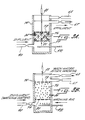
- a filtration system of the invention is represented in a cutaway perspective view generally at 72 in Figure 2.
- the filtration system includes a housing 74 and a filtration bed 76 contained within the housing between two perforated plates, a movable upper plate 78 and a fixed lower plate 80.
- the perforated plates contain a plurality of apertures 82 through which wastewater can enter and exit the filter bed.
- the apertures are sized to permit the wastewater freely to enter and exit the filter bed while substantially precluding the individual filter media components 84 from being displaced outside the filter bed.
- the individual filter media components 84 are illustrated in an enlarged perspective view generally at 86.
- the upper plate 78 is a vertically movable plate and its movement up and down is actuated by a piston 88 disposed above the plate.
- the plate is moved as necessary to control the degree of compression of the filter media in the bed.
- the mechanism for moving the upper plate up and down can be designed to avoid extending substantially above the top most portion of the filter housing, which can reduce the free vertical space needed to accommodate the filter.
- FIG. 3A The operation of the filter in various modes is represented in Figures 3A through 3C in a longitudinal schematic cross section through the filter housing 74 .
- the filter bed 76 is compressed by the top movable plate 78 .
- Influent wastewater enters a distribution plenum 79 at the bottom most portion of the filter housing through a conduit 90 .
- the wastewater distributed evenly over the filter bed by the plenum, travels upwardly through the housing and enters the filter bed 76 through the apertures in the lower plate 80.
- the effluent filtered wastewater exits the filter bed through the apertures in the upper plate and is conveyed out of the filter housing through conduit 67. Suspended solids are trapped by the media.
- channeling of wastewater around the media in the region of the wall of the housing can be alleviated by providing a flow distribution device adjacent the apparatus wall to direct the flow of wastewater away from the wall and into the filter bed.
- a flow distribution device adjacent the apparatus wall to direct the flow of wastewater away from the wall and into the filter bed.
- a short baffle can be attached to the wall of the housing at regular intervals to extend into the filter bed by about two inches and at an angle of about 45 degrees upward to direct the flow of wastewater off the wall and into the filter bed.
- the effluent conduit 67 is closed and conduit 68 is opened (Figure 3B) to recycle the wastewater effluent from the filtration system to the activated sludge reactor 56 or other primary treatment location.
- the upper movable plate 78 is moved vertically upward to mechanically expand the filter bed to an uncompressed condition.
- Air or other gas is injected below the filter bed through conduits 92 and 94 ( Figure 2) to aid in expanding the bed and mechanically shearing the trapped solids from the filter media.
- air is injected on first one side and then the other side of the filter bed to increase the mechanical effect by alternating air injection between conduits 92 and 94.
- the filter bed is flushed for a suitable period of time to remove residual solids prior to resuming filtration ( Figure 3C).
- the filter bed is compressed as in the filtration mode and the air supply is turned off. However, in the flush mode, the flush water is provided through conduit 68 to the activated sludge reactor for additional treatment rather than being taken off through effluent conduit 67.
- the major parameters that impact filtration performance are the filtration rate, the depth of the media, the collector size, the porosity, and the influent quality.
- suspended solids in the influent and effluent wastewater can be correlated to turbidity, as is known to the skilled artisan.
- Turbidity monitoring equipment can be used in a conventional manner, as is believed to be understood by the skilled artisan, to determine the influent turbidity and to compare the influent turbidity to the effluent turbidity so as to monitor the performance of the filter.
- Porosity and collector size of the filter media impact effluent water quality and the development of headloss across the filter medium.
- Porosity is typically considered to be the ratio, expressed as a percentage, of the void spaces, or interstices, of the filter media to the total volume of the filter media.
- the collector size is typically considered to be the average diameter of the grains in the filter bed in a typical filter that includes a granular filtration medium.
- the collector size is normally defined as the average spacing between the pores in the filter bed.
- the fluid to be filtered flows around the filtering medium in conventional sand or anthracite filters that are used in connection with tertiary wastewater treatment.
- Filter media has been found useful in the practice of the invention in which the fluid flows through the medium, rather than around the medium, unlike conventional filtration media.
- Filter media useful in the practice of the invention is also compressible, unlike conventional sand or anthracite media.
- the collector size and the porosity, or void ratio, of the medium can be modified in accordance with the characteristics of the influent wastewater because the filter medium is compressible. Bed porosity and the collector size of the media is adjusted by adjusting the position of the upper movable plate.
- the porosity and collector size of the filter medium can be altered during filtration to overcome the effect on effluent quality of variations in daily influent water quality and to increase the useful life of the filtration medium between washing steps.
- the filter bed can be mechanically expanded somewhat during filtration as headloss develops without a loss of filtration efficiency. Headloss through the medium can be monitored using pressure sensing equipment as is known in the art. Backwashing of the filter can be particularly efficient because the size of the filter bed and its porosity can be increased mechanically.
- the filtration medium has low density, which typically is just slightly above the density of water.
- the porosity of the filter medium is estimated to be about 88 to 90 percent and the porosity of the uncompacted filter bed (Figure 3B) is about 92 to 94 percent.
- the fibrous lumps have many bundled crimpy fibers 32 formed by providing synthetic fibers of 20 to 200 denier with 2 to 10 crimps per inch.
- the bundled crimpy fibers are wrung and bundled at the core portion thereof by a binding wire 34 .
- the bundled crimpy fibers are rounded to provide the fibrous lump in the form of a substantial sphere having a diameter of 10 to 50 mm.
- a fiber having a higher specific gravity than water for example, a polyvinylidene chloride fiber, is said to be optimal for the synthetic fiber to constitute the crimpy fiber.
- the fibers can also be made from polyvinylchloride, polyethylene fiber, or other synthetic fibers.
- a filter as described above was evaluated to determine a range of useful operating parameters by adjusting the degree of compression of the filter bed at various flow rates and considering the influent and effluent turbidities, the removal efficiency for removal of suspended solids from the wastewater by the filter, and the development of headloss across the filter bed.
- the test unit had the following characteristics as shown in Table 1.
- Effluent turbidity was plotted against influent turbidity in a series of 16 runs at four different filtration rates and four different filter bed compression levels.
- the filtration rates varied from 205 to 1230 L/m 2 •min (5 to 30 gal/ft 2 •min) and compression rates varied from 0 to 40 percent compression to evaluate influent and effluent turbidity, headloss across the filter medium, and fractional turbidity removal based on the influent and effluent turbidity.
- the uncompacted filter bed at 0 percent compression was approximately 30 inches (760 millimeters) deep. Filtration rates, compression levels, and medium depths for each run are summarized in Table 2 below. Run no.
- Filtration Rate Compression ratio % Medium depth Estimated porosity % L/m 2 •min gal/ft 2 •min mm in 1 205 5 0 760 30 92 2 205 5 15 650 25.5 90.5 3 205 5 30 530 21 88.5 4 205 5 40 460 18 87 5 410 10 0 760 30 92 6 410 10 15 650 25.5 90.5 7 410 10 30 530 21 88.5 8 410 10 40 460 18 87 9 820 20 0 760 30 92 10 820 20 15 650 25.5 90.5 11 820 20 30 530 21 88.5 12 820 20 40 460 18 87 13 1230 30 0 760 30 92 14 1230 30 15 650 25.5 90.5 15 1230 30 30 530 21 88.5 16 1230 30 40 460 18 87
- the backwash flow rate for the filtration unit was set in a conventional manner using a bypass loop located in the conduit supplying influent to the filtration unit.
- the bypass loop was equipped with a ball valve that was used to regulate the backwash flow rate.
- the influent conduit was equipped with a gate valve followed by an automatic ball valve opposite the bypass loop.
- the gate valve was used to regulate the filtration rate and the automatic ball valve was used to divert flow to the bypass loop where the backwash flow rate could be adjusted as soon as the backwash cycle started.
- the backwash flow rate was set to approximately 410 L/m 2 •min. (10 gal/ft 2 •min) for all of the 16 runs.
- a terminal headloss value of 2540 mm (100 inches) of water was selected for all of the runs. Turbidity sampling was accomplished at about 400 ml/min for all runs. Suspended solids were correlated to turbidity values according to standard, art recognized methods.
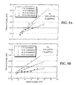
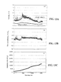
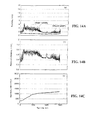
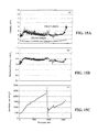
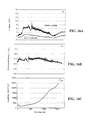
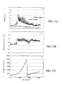
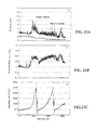
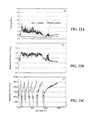
- Figures 8A through 23C The results of the 16 runs are plotted in Figures 8A through 23C.
- Figures A are plots of effluent and influent turbidity against time.
- Figures 8 through 11 are for filtration of wastewater at a rate of 205 L/m 2 •min (5 gal/ft 2 •min).
- Figure 8 shows an initial bed depth of 30 inches at 0 percent compression.
- Figure 9 is at 15 percent compression;
- Figure 10 is at 30 percent compression;
- Figure 11 is at 40 percent compression.
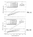
- Figures 12 through 15 are at a filtration rate of 410 L/m 2 •min (10 gal/ft 2 •min) at four different bed compressions of 0 percent, 15 percent, 30 percent, and 40 percent.
- Figures 16 through 19 are taken at a filtration rate of 820 L/m 2 •min (20 gal/ft 2 •min) at four different bed compressions of 0 percent, 15 percent, 30 percent, and 40 percent.
- Figures 20 through 23 are taken at 1230 L/m 2 •min (30 gal/ft 2 •min) at four different bed compressions of 0 percent, 15 percent, 30 percent, and 40 percent.
- the collector size which can be defined as the size of the grains in a granular filter medium, can be defined with the filter medium as used in the invention as the average pore spacing within the structure of the individual filter lump. Trapped particles tend to decrease the collector size of the medium and results in an increase in the removal of additional particles by interception and straining.
- the collector size is defined as the nominal diameter of one fibrous lump. The difference between the initial collector size and the collector size at any time during the filtration cycle is much larger when the flow occurs around the medium, and therefore filter ripening becomes more important at low filtration rates.
- the porosity, depth of the filter bed, and collector size can all be altered, even during the filtration cycle, because the filter medium is compressible.
- the maximum removal efficiency that can be achieved is somewhat dependent on the characteristics of the material being filtered, which is primarily colloidal. Removal efficiency typically increases as the filter bed is compressed until some maximum level is reached. For example, as shown in Figures 8B through 11B, the average removal efficiency of the filter increased from about 55 percent at 0 percent bed compression to about 61 percent at 30 percent bed compression when the flow rate was at 205 L/m 2 •min (5 gal/ft 2 •min). At 410 L/m 2 •min (10 gal/ft 2 •min), the removal efficiency of the filter increased from 48 percent at 0 percent bed compression to 65 percent at 30 percent bed compression.
- the maximum removal efficiency in the practice of the invention occurs at different compression levels as the filtration rate is increased and the characteristics of the influent to the filter change. Maximum removal efficiency was observed to occur at 40 percent bed compression at a filtration rate of 410 L/m 2 •min (10 gal/ft 2 •min). However, at flow rates of 820 to 1230 L/m 2 •min (20 to 30 gal/ft 2 •min), maximum removal efficiency occurred at 30 percent bed compression.
- the filtration system of the invention can be usefully operated at flow rates above 1230 L/m 2 •min (30 gal/ft 2 •min) depending on the influent quality, the desired effluent quality, and the head loss across the filter.
- the filter influent typically is taken from a primary clarifier.
- the filter should be operable at increased flow rates above 1230 L/m 2 •min (30 gal/ft 2 •min) so long as the increase in the rate of head loss across the filter provides economical operation.
- Flow rates of from about 1640 L/m 2 •min (40 gal/ft 2 •min) to 2050 L/m 2 •min (50 gal/ft 2 •min) should be useful in this regard.
- removal efficiency is not significantly impacted by the filtration rate. Instead, removal efficiency is impacted more by the compression of the filter medium.
- the removal efficiency appears to be lower when the influent turbidity is in the range of from 1.5 to 3 NTU.
- the particle size of the influent solids is shifted more towards the smaller colloidal size particles than the typical particle size distribution observed when the influent turbidity is higher than 3 NTU.
- the turbidity of the secondary effluent from a typical activated sludge wastewater treatment plant is in the range of from 3 to 8 NTU. Accordingly, in the case where the turbidity is in the range of from 1.5 to less than about 3 NTU, the performance of the filter cannot be evaluated solely based on the removal efficiency data.
- the effluent turbidity typically is equal to or lower than 2 NTU for influent turbidity values of up to about 8 NTU when the flow rate is from about 410 to 1230 L/m 2 •min (10 to 30 gal/ft 2 •min). If the influent turbidity is from about 7 to 10 NTU, then chemical addition normally is required to produce an effluent with an average turbidity of 2 NTU or less.
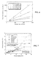
- Clean filter headloss the development of headloss during filtration, and the development of headloss with the accumulation of solids is effected by the filtration rate and the compression of the bed. Clean filter headloss is plotted against filtration rate for the 4 filtration rates that were evaluated at 4 different bed compressions in Figure 6.
- the initial headloss at a flowrate of 205 L/m 2 •min (5 gal/ft 2 •min) and at 0 percent bed compression is 63 mm (2.5 inches) of water.
- This initial value increases linearly to a value of 127 mm (5 inches) of water at a flowrate of 410 L/m 2 •min (10 gal/ft 2 •min) at 0 percent compression.
- the linear increase in headloss tends to indicate that the flow regimen through the filter is laminar.
- the suspended solids accumulation in the medium at any time is calculated by the following mass balance equation where
- the filtration system described herein was evaluated with respect to the amount of water that was produced per day. Taking into account the water used for backwashing, the water production rate for various filtration rates and bed compression ratios is reported in the last two columns of Table 3. As shown, it is possible to produce 1,672,800 L/m 2 •day (41,000 gal/ft 2 •day) at a filtration rate of 1230 L/m 2 •min (30 gal/ft 2 •min) at a bed compression of 15 percent.
- the ability to compress the filter medium is a significant factor in the operation of the filter of the invention as described.
- the porosity of the bed can be modified to meet the characteristics of the influent liquid.
- the porosity of the bed can be altered without significantly effecting filtration efficiency to delay the onset of an unacceptable headloss across the filter medium, thus further extending the useful life of the filter between backwashing cycles. Because the bed is so highly porous, significantly higher filtration rates can be used as compared to conventional granular medium filters which filter from 80 to 410 L/m 2 •min (2 to 10 gal/ft 2 •min). In contrast, filtration rates of from 820 to 1230 L/m 2 •min (20 to 30 gal/ft 2 •min) are achievable in the practice of the invention.
- the optimum filtration rate appears to be in the range of from 820 to 1230 L/m 2 •min (20 to 30 gal/ft 2 •min) at a bed compression of from about 15 to 30 percent.
- Effluent turbidity values of 2 NTU or lower can be achieved without chemical addition for influent turbidity values of up to approximately 8 NTU when the flow is between 820 to 1230 L/m 2 •min (20 to 30 gal/ft 2 •min) at a bed compression ratio of from about 15 to 40 percent.
- Secondary effluent can be used as the backwash water.
- a flowrate of 410 L/m 2 •min (10 gal/ft 2 •min) was observed to be sufficient to clean the filter medium.
- the percentage of backwash water required at filtration rates of 820 and 1230 L/m 2 •min (20 to 30 gal/ft 2 •min) and at bed compression values of between 20 and 30 percent varied from about 1.1 to 3.1 percent, which is extremely efficient by comparison with conventional technologies.
Claims (30)
- Filtrationsvorrichtung (72), umfassend:Ein Filtergehäuse (74), das einen Fluideinlass (64) und einen Fluidauslass (67) aufweist;ein komprimierbares faseriges klumpenförmiges Filtrationsmittel (30) mit einstellbarer Porosität, die als das Verhältnis (%) von Leerräumen oder Zwischenräumen des Filtermittels zu dem gesamten Volumen des Filtermittels definiert ist, und Abscheidergröße, die als der mittlere Abstand zwischen den Poren in dem Filtermittel definiert ist, welches in einem Filterbett (76) innerhalb des Filtergehäuses (74) zwischen dem Fluideinlass (64) und dem Fluidauslass (67) angeordnet ist;ein Mittel zum Einstellen der Porosität und der Abscheidergröße des Filtrationsmittels (30), wobei das Mittel Mittel zum Komprimieren umfasst, die derart angeordnet sind, dass sie das Filtrationsmittel (30) mit einem Komprimierungsgradienten komprimieren, der von mehr komprimiert zu weniger komprimiert in einer Richtung entgegen dem Fluss des Fluids verläuft, so dass die Filtration in einer Richtung von einem porösen zu einem weniger porösen Filter verläuft.
- Vorrichtung (72) nach Anspruch 1, wobei das Mittel zum Komprimieren des Filtrationsmittels (30) umfasst:Eine erste Lochplatte (80), die unbewegbar innerhalb der Vorrichtung (72) angeordnet ist;eine zweite Lochplatte (78), die bewegbar innerhalb der Vorrichtung (72) und mit einem Zwischenraum oberhalb der ersten Lochplatte (80) angeordnet ist, wobei das Filtrationsmittel zwischen den zwei Platten positioniert ist; undein Mittel zum selektiven Bewegen der bewegbar angeordneten zweiten Lochplatte (78) hin zu und weg von der ersten Lochplatte (80), wobei das Mittel oberhalb der zweiten Lochplatte (78) angeordnet ist.
- Vorrichtung (72) nach Anspruch 2, die ferner Mittel zum Bewegen des Filtermittels (30) in einen unkomprimierten Zustand umfasst, um das Filtermittel (30) zu reinigen.
- Vorrichtung (72) nach Anspruch 1, wobei der Fluideinlass (64) unterhalb des Fluidauslasses (67) angeordnet ist und der Filter in einer Aufwärtsströmungsbetriebsart betrieben ist.
- Vorrichtung (72) nach Anspruch 1, wobei das Mittel zum Einstellen der Porosität und der Abscheidergröße des Filtrationsmittels (30) während der Filtration einstellbar ist.
- Vorrichtung (72) nach Anspruch 1, wobei das Filterbett (76) vor der Komprimierung eine Porosität von ungefähr 92 bis 94% und eine Porosität von ungefähr 87 bis 90% aufweist, wenn es komprimiert ist.
- Vorrichtung (72) nach Anspruch 1, wobei das Filterbett (76) vor der Komprimierung eine Tiefe von mindestens etwa 30 Inchen (760 mm) aufweist.
- Vorrichtung (72) nach Anspruch 1, wobei die Vorrichtung (72) zur Filtration bei einer Fluidflussrate von ungefähr 205 bis 1230 L/m2 min (5 bis 30 gal/ft2 min), bei einem Bettkomprimierungsverhältnis von ungefähr 0 bis 40 Prozent und bei einer Rückspülungsrate von ungefähr 1 bis 6 Prozent, bezogen auf das gesamte Fluid, das durch den Filter tritt, betreibbar ist.
- Vorrichtung (72) nach Anspruch 8, wobei die Fluidflussrate ungefähr 410 bis 1230 L/m2 min (10 bis 30 gal/ft2 min) beträgt.
- Vorrichtung (72) nach Anspruch 8, wobei die Fluidflussrate ungefähr 820 bis 1230 L/m2 min (20 bis 30 gal/ft2 min) beträgt.
- Vorrichtung (72) nach den Ansprüchen 1, 2 und 4, wobei die Porosität des Filterbetts (76) von einer Porosität von ungefähr 92 bis 94% vor der Komprimierung bis zu einer Porosität von ungefähr 87 bis 90%, wenn es komprimiert ist, eingestellt werden kann.
- Vorrichtung (72) nach Anspruch 1, wobei die Vorrichtung (72) zur Filtration bei einer Fluidflussrate von ungefähr 820 bis 1230 L/m2 min (20 bis 30 gal/ft2 min) bei einem Bettkomprimierungsverhältnis von ungefähr 15 bis 40 Prozent und bei einer Rückspülungsrate von ungefähr 1 bis 6 Prozent, bezogen auf das gesamte Fluid, das durch den Filter tritt, betreibbar ist.
- Filtrationsvorrichtung (72) für die Abwasserbehandlung nach den Ansprüchen 1, 2 und 4, wobeidas Filtrationsmittel (30) zwischen der ersten und zweiten Lochplatte (80, 78) angeordnet ist und das Filterbett (76) definiert,wobei das Filterbett (76) zum Reinigen expandiert wird; undwobei Mittel vorgesehen sind, um ein Gas in das Abwasser einzubringen, wenn das Filterbett (76) zum Reinigen expandiert ist.
- Vorrichtung (72) nach Anspruch 13, wobei der Einlass (64) einen Raum (79) umfasst, um das Abwasser gleichmäßig verteilt durch die erste Lochplatte (80) zu leiten.
- Vorrichtung (72) nach Anspruch 14, wobei die Vorrichtung (72) zur Filtration betreibbar ist, um die Trübheit von einfließendem Abwasser von ungefähr 8 NTU auf ungefähr 2 NTU bei einer Abwasserflussrate von ungefähr 820 bis 1230 L/m2 min (20 bis 30 gal/ft2 min), bei einem Bettkomprimierungsverhältnis von ungefähr 15 bis 40 Prozent und bei einer Rückspülungsrate von ungefähr 1 bis 6 Prozent, bezogen auf das gesamte Abwasser, das durch den Filter tritt, zu reduzieren.
- Vorrichtung (72) nach Anspruch 15, wobei die Rückspülungsflussrate ungefähr 1 bis 3 Prozent, bezogen auf das gesamte Abwasser, das durch den Filter tritt, beträgt.
- Verfahren zum Filtern eines Fluids, umfassend die Schritte:a) Komprimieren eines komprimierbaren faserigen klumpenförmigen Filtrationsmittels, das in einem Filterbett angeordnet ist, um einen Porositätsgradienten in dem Filterbett zu definieren, der von mehr porös zu weniger porös in einer Richtung entgegen dem Fluss des Fluids verläuft, so dass die Filtration in einer Richtung von einem poröseren zu einem weniger poröseren Filterbett verläuft; undb) Leiten von Fluid durch das Filterbett;c) periodisches Expandieren des Filterbetts, während weiterhin Fluid durch das Filterbett geleitet wird, um das Filtrationsmittel zu reinigen.
- Verfahren nach Anspruch 17, wobei das Fluid eine Flüssigkeit ist und Gas zur zusätzlichen Reinigung des Mittels in die Flüssigkeit eingebracht wird, bevor die Flüssigkeit in das Filterbett eintritt.
- Verfahren nach Anspruch 17, das ferner den Schritt des Entfernens zunehmend kleinerer Partikel aus dem Fluid umfasst, während die Filtration von einem durchlässigeren zu einem weniger durchlässigen Mittel verläuft.
- Verfahren nach Anspruch 17, das ferner den Schritt des Veränderns der Komprimierung des Mittels während der Filtration als Reaktion auf die Beschaffenheiten des eintretenden Fluids umfasst.
- Verfahren nach Anspruch 17, das ferner die Schritte des Überwachens des Druckverlusts entlang dem Filterbett und des Veränderns der Komprimierung des Mittels während der Filtration umfasst, um den Druckverlust zu vermindern und um die Zeit zwischen den periodischen Reinigungen zu verlängern.
- Verfahren zum Filtern einer Flüssigkeit gemäß Anspruch 17, um Partikel daraus zu entfernen, ferner umfassend die Schritte:b1) Entfernen zunehmend kleinerer Partikel aus der Flüssigkeit, während die Filtration von einem poröseren zu einem weniger poröseren Mittel verläuft;b2) Überwachen des Druckverlusts entlang dem Filterbett;c) periodisches Expandieren des Filterbetts, wenn ein maximaler Druckverlust erreicht ist, während weiterhin Flüssigkeit durch das Filterbett geleitet wird, um das Filtrationsmittel zu reinigen.
- Verfahren nach Anspruch 22, wobei Flüssigkeit durch das expandierte Filterbett bei einer Rate geleitet wird, die ungefähr 1 bis 6% des Gesamtflüssigkeitsflusses durch das Filterbett beträgt.
- Verfahren nach Anspruch 17, wobei das Filterbett auf ein Komprimierungsverhältnis von ungefähr 15 bis 40% komprimiert wird, wobei Flüssigkeit durch das komprimierte Filterbett bei einer Flussrate von ungefähr 205 bis 1230 L/m2 min (5 bis 30 gal/ft2 min) geleitet wird und wobei Rückspülungsflüssigkeit durch den Filter bei einer Rückspülungsrate von ungefähr 1 bis 6%, bezogen auf die gesamte Flüssigkeit, die durch den Filter tritt, geleitet wird.
- Verfahren nach Anspruch 22, wobei das Filterbett von einer Porosität von ungefähr 92 bis 94% bis zu einer minimalen Porosität von ungefähr 87 bis 90% komprimiert wird.
- Verfahren nach Anspruch 22, wobei die maximale Beseitigungseffizienz bei einer Bettkomprimierung von 40% bei einer Flüssigkeitsflussrate von 820 L/m2 min (20 gal/ft2 min) und einer Bettkomprimierung von 30% bei einer Flussrate von 1230 L/m2 min erreicht wird.
- Verfahren zur tertiären Abwasserbehandlung, umfassend die Schritte:a) Behandeln des Abwassers in einem Belebtschlammreaktor, um ein primär gereinigtes Abwasser zu liefern,b) Behandeln des primär gereinigten Abwassers in einem Klärapparat, um ein sekundär gereinigtes Abwasser zu liefern;c) Filtern des sekundär gereinigten Abwassers gemäß dem Verfahren nach Anspruch 17, um ein tertiär gereinigtes Abwasser zu liefern.
- Verfahren nach Anspruch 27, wobei die Filtrationsvorrichtung zur Filtration betreibbar ist, um die Trübheit von einfließendem Abwasser von ungefähr 8 NTU auf ungefähr 2 NTU bei einer Abwasserflussrate von ungefähr 820 bis 1230 L/m2 min (20 bis 30 gal/ft2 min), bei einem Bettkomprimierungsverhältnis von ungefähr 15 bis 40 Prozent und bei einer Rückspülungsrate von ungefähr 1 bis 6 Prozent, bezogen auf das gesamte Abwasser, das durch den Filter tritt, zu reduzieren.
- Verfahren nach Anspruch 28, wobei die Rückspülungsflussrate ungefähr 1 bis 3 Prozent, bezogen auf das gesamte Abwasser, das durch den Filter tritt, beträgt.
- Verfahren nach Anspruch 27, wobei die Wassererzeugungsrate eines Filters von zumindest 76 cm (30 Inch) unkomprimierter Tiefe und bei einer Abwasserqualität von 2 NTU oder weniger, bezogen auf eine einfließende Qualität von bis zu 8 NTU, über 1.000.000 L/m2 Tag (28.000 gal/ft2 Tag) beträgt.
Applications Claiming Priority (5)
| Application Number | Priority Date | Filing Date | Title |
|---|---|---|---|
| US3264396P | 1996-12-10 | 1996-12-10 | |
| US32643P | 1996-12-10 | ||
| US98053797A | 1997-12-01 | 1997-12-01 | |
| US980537 | 1997-12-01 | ||
| PCT/US1997/022327 WO1998025681A1 (en) | 1996-12-10 | 1997-12-09 | High rate filtration system |
Publications (2)
| Publication Number | Publication Date |
|---|---|
| EP0949947A1 EP0949947A1 (de) | 1999-10-20 |
| EP0949947B1 true EP0949947B1 (de) | 2002-03-27 |
Family
ID=26708705
Family Applications (1)
| Application Number | Title | Priority Date | Filing Date |
|---|---|---|---|
| EP97950851A Expired - Lifetime EP0949947B1 (de) | 1996-12-10 | 1997-12-09 | Hochleistungsfiltrationssystem |
Country Status (7)
| Country | Link |
|---|---|
| EP (1) | EP0949947B1 (de) |
| JP (1) | JP2000511823A (de) |
| AT (1) | ATE214965T1 (de) |
| AU (1) | AU729854C (de) |
| CA (1) | CA2274778C (de) |
| DE (1) | DE69711436T2 (de) |
| WO (1) | WO1998025681A1 (de) |
Families Citing this family (3)
| Publication number | Priority date | Publication date | Assignee | Title |
|---|---|---|---|---|
| JP6156993B2 (ja) * | 2013-08-02 | 2017-07-05 | 株式会社industria | フィルタ装置及び流体浄化システム |
| CN110621998B (zh) * | 2017-05-19 | 2022-10-28 | 哈希公司 | 水处理中的膜完整性监测 |
| JP6830037B2 (ja) * | 2017-05-31 | 2021-02-17 | メタウォーター株式会社 | 下水処理システム |
Family Cites Families (4)
| Publication number | Priority date | Publication date | Assignee | Title |
|---|---|---|---|---|
| DE312993C (de) * | ||||
| JPS5936513A (ja) * | 1982-08-26 | 1984-02-28 | Kindai:Kk | 集塵フイルタと製造方法 |
| SU1754159A1 (ru) * | 1990-08-13 | 1992-08-15 | Военная академия тыла и транспорта | Фильтр дл очистки жидкостей |
| JP3734227B2 (ja) * | 1991-10-18 | 2006-01-11 | 三井造船株式会社 | 上向流式高速濾過装置 |
-
1997
- 1997-12-09 AT AT97950851T patent/ATE214965T1/de not_active IP Right Cessation
- 1997-12-09 AU AU53745/98A patent/AU729854C/en not_active Expired
- 1997-12-09 WO PCT/US1997/022327 patent/WO1998025681A1/en active IP Right Grant
- 1997-12-09 JP JP10526835A patent/JP2000511823A/ja active Pending
- 1997-12-09 EP EP97950851A patent/EP0949947B1/de not_active Expired - Lifetime
- 1997-12-09 CA CA002274778A patent/CA2274778C/en not_active Expired - Lifetime
- 1997-12-09 DE DE69711436T patent/DE69711436T2/de not_active Expired - Lifetime
Also Published As
| Publication number | Publication date |
|---|---|
| ATE214965T1 (de) | 2002-04-15 |
| DE69711436T2 (de) | 2002-08-08 |
| JP2000511823A (ja) | 2000-09-12 |
| DE69711436D1 (de) | 2002-05-02 |
| AU729854B2 (en) | 2001-02-08 |
| EP0949947A1 (de) | 1999-10-20 |
| WO1998025681A1 (en) | 1998-06-18 |
| CA2274778C (en) | 2004-07-20 |
| AU729854C (en) | 2001-08-23 |
| AU5374598A (en) | 1998-07-03 |
| CA2274778A1 (en) | 1998-06-18 |
Similar Documents
| Publication | Publication Date | Title |
|---|---|---|
| US7572383B2 (en) | Process for filtering a fluid with a compressible filtration media | |
| US3459302A (en) | Apparatus and method of filtering solids from a liquid effluent | |
| Ljunggren | Micro screening in wastewater treatment-an overview | |
| KR101446273B1 (ko) | 수두차를 이용한 상향류 모래 여과장치의 운영 방법 및 이를 이용한 수처리 방법 | |
| US4659462A (en) | Apparatus for pretreatment of water using a bed of granular activated carbon | |
| US4162216A (en) | Process for removal of suspended solids from liquid | |
| US4190543A (en) | Waste water treatment apparatus | |
| US5252230A (en) | Granulated filter for the filtration of fine graded suspensions | |
| JP3698678B2 (ja) | 細砂緩速ろ過装置 | |
| EP0949947B1 (de) | Hochleistungsfiltrationssystem | |
| US5900220A (en) | Soda ash processing method | |
| USRE28458E (en) | Apparatus and method of filtering solids from a liquid effluent | |
| Bourgeous et al. | Performance Evaluation of a Cloth‐Media Disk Filter for Wastewater Reclamation | |
| CN206466978U (zh) | 一种具有反冲洗功能的三室四层过滤器 | |
| NO813255L (no) | Fremgangsmaate og apparat for behandling av avvann | |
| Wang | Diatomaceous earth precoat filtration | |
| MXPA99005490A (en) | High rate filtration system | |
| GB1601380A (en) | Process and apparatus for purification of effluents | |
| CA1306421C (en) | Method and apparatus for pretreatment of water using a bed of granular activated carbon | |
| RU2116975C1 (ru) | Устройство для очистки нефтесодержащих сточных вод | |
| KR200242570Y1 (ko) | 오폐수 처리용 여과기 | |
| KR101269582B1 (ko) | 액상화 현상을 이용한 모래 여과 장치 및 방법 | |
| KR101387606B1 (ko) | 유지관리가 간편한 수처리용 상향류 여과조 | |
| CA1181698A (en) | Waste treatment process and apparatus | |
| Ødegaard et al. | Enhanced primary treatment in floating filters |
Legal Events
| Date | Code | Title | Description |
|---|---|---|---|
| PUAI | Public reference made under article 153(3) epc to a published international application that has entered the european phase |
Free format text: ORIGINAL CODE: 0009012 |
|
| 17P | Request for examination filed |
Effective date: 19990706 |
|
| AK | Designated contracting states |
Kind code of ref document: A1 Designated state(s): AT BE CH DE DK ES FI FR GB GR IE IT LI LU MC NL PT SE |
|
| 17Q | First examination report despatched |
Effective date: 19991119 |
|
| GRAG | Despatch of communication of intention to grant |
Free format text: ORIGINAL CODE: EPIDOS AGRA |
|
| GRAG | Despatch of communication of intention to grant |
Free format text: ORIGINAL CODE: EPIDOS AGRA |
|
| GRAH | Despatch of communication of intention to grant a patent |
Free format text: ORIGINAL CODE: EPIDOS IGRA |
|
| GRAH | Despatch of communication of intention to grant a patent |
Free format text: ORIGINAL CODE: EPIDOS IGRA |
|
| REG | Reference to a national code |
Ref country code: GB Ref legal event code: IF02 |
|
| GRAA | (expected) grant |
Free format text: ORIGINAL CODE: 0009210 |
|
| AK | Designated contracting states |
Kind code of ref document: B1 Designated state(s): AT BE CH DE DK ES FI FR GB GR IE IT LI LU MC NL PT SE |
|
| PG25 | Lapsed in a contracting state [announced via postgrant information from national office to epo] |
Ref country code: LI Free format text: LAPSE BECAUSE OF FAILURE TO SUBMIT A TRANSLATION OF THE DESCRIPTION OR TO PAY THE FEE WITHIN THE PRESCRIBED TIME-LIMIT Effective date: 20020327 Ref country code: IT Free format text: LAPSE BECAUSE OF FAILURE TO SUBMIT A TRANSLATION OF THE DESCRIPTION OR TO PAY THE FEE WITHIN THE PRESCRIBED TIME-LIMIT;WARNING: LAPSES OF ITALIAN PATENTS WITH EFFECTIVE DATE BEFORE 2007 MAY HAVE OCCURRED AT ANY TIME BEFORE 2007. THE CORRECT EFFECTIVE DATE MAY BE DIFFERENT FROM THE ONE RECORDED. Effective date: 20020327 Ref country code: GR Free format text: LAPSE BECAUSE OF FAILURE TO SUBMIT A TRANSLATION OF THE DESCRIPTION OR TO PAY THE FEE WITHIN THE PRESCRIBED TIME-LIMIT Effective date: 20020327 Ref country code: FI Free format text: LAPSE BECAUSE OF FAILURE TO SUBMIT A TRANSLATION OF THE DESCRIPTION OR TO PAY THE FEE WITHIN THE PRESCRIBED TIME-LIMIT Effective date: 20020327 Ref country code: CH Free format text: LAPSE BECAUSE OF FAILURE TO SUBMIT A TRANSLATION OF THE DESCRIPTION OR TO PAY THE FEE WITHIN THE PRESCRIBED TIME-LIMIT Effective date: 20020327 Ref country code: AT Free format text: LAPSE BECAUSE OF FAILURE TO SUBMIT A TRANSLATION OF THE DESCRIPTION OR TO PAY THE FEE WITHIN THE PRESCRIBED TIME-LIMIT Effective date: 20020327 |
|
| REF | Corresponds to: |
Ref document number: 214965 Country of ref document: AT Date of ref document: 20020415 Kind code of ref document: T |
|
| REG | Reference to a national code |
Ref country code: CH Ref legal event code: EP |
|
| REF | Corresponds to: |
Ref document number: 69711436 Country of ref document: DE Date of ref document: 20020502 |
|
| REG | Reference to a national code |
Ref country code: IE Ref legal event code: FG4D |
|
| PG25 | Lapsed in a contracting state [announced via postgrant information from national office to epo] |
Ref country code: SE Free format text: LAPSE BECAUSE OF FAILURE TO SUBMIT A TRANSLATION OF THE DESCRIPTION OR TO PAY THE FEE WITHIN THE PRESCRIBED TIME-LIMIT Effective date: 20020627 Ref country code: PT Free format text: LAPSE BECAUSE OF FAILURE TO SUBMIT A TRANSLATION OF THE DESCRIPTION OR TO PAY THE FEE WITHIN THE PRESCRIBED TIME-LIMIT Effective date: 20020627 Ref country code: DK Free format text: LAPSE BECAUSE OF FAILURE TO SUBMIT A TRANSLATION OF THE DESCRIPTION OR TO PAY THE FEE WITHIN THE PRESCRIBED TIME-LIMIT Effective date: 20020627 |
|
| PG25 | Lapsed in a contracting state [announced via postgrant information from national office to epo] |
Ref country code: ES Free format text: LAPSE BECAUSE OF FAILURE TO SUBMIT A TRANSLATION OF THE DESCRIPTION OR TO PAY THE FEE WITHIN THE PRESCRIBED TIME-LIMIT Effective date: 20020925 |
|
| REG | Reference to a national code |
Ref country code: CH Ref legal event code: PL |
|
| PG25 | Lapsed in a contracting state [announced via postgrant information from national office to epo] |
Ref country code: LU Free format text: LAPSE BECAUSE OF NON-PAYMENT OF DUE FEES Effective date: 20021209 |
|
| PLBE | No opposition filed within time limit |
Free format text: ORIGINAL CODE: 0009261 |
|
| STAA | Information on the status of an ep patent application or granted ep patent |
Free format text: STATUS: NO OPPOSITION FILED WITHIN TIME LIMIT |
|
| 26N | No opposition filed |
Effective date: 20021230 |
|
| PG25 | Lapsed in a contracting state [announced via postgrant information from national office to epo] |
Ref country code: MC Free format text: LAPSE BECAUSE OF NON-PAYMENT OF DUE FEES Effective date: 20030701 |
|
| REG | Reference to a national code |
Ref country code: FR Ref legal event code: PLFP Year of fee payment: 19 |
|
| REG | Reference to a national code |
Ref country code: FR Ref legal event code: PLFP Year of fee payment: 20 |
|
| PGFP | Annual fee paid to national office [announced via postgrant information from national office to epo] |
Ref country code: DE Payment date: 20161206 Year of fee payment: 20 Ref country code: GB Payment date: 20161207 Year of fee payment: 20 Ref country code: IE Payment date: 20161209 Year of fee payment: 20 Ref country code: FR Payment date: 20161111 Year of fee payment: 20 Ref country code: NL Payment date: 20161212 Year of fee payment: 20 |
|
| PGFP | Annual fee paid to national office [announced via postgrant information from national office to epo] |
Ref country code: BE Payment date: 20161024 Year of fee payment: 20 |
|
| REG | Reference to a national code |
Ref country code: DE Ref legal event code: R071 Ref document number: 69711436 Country of ref document: DE |
|
| REG | Reference to a national code |
Ref country code: NL Ref legal event code: MK Effective date: 20171208 |
|
| REG | Reference to a national code |
Ref country code: GB Ref legal event code: PE20 Expiry date: 20171208 |
|
| REG | Reference to a national code |
Ref country code: IE Ref legal event code: MK9A |
|
| REG | Reference to a national code |
Ref country code: BE Ref legal event code: MK Effective date: 20171209 |
|
| PG25 | Lapsed in a contracting state [announced via postgrant information from national office to epo] |
Ref country code: GB Free format text: LAPSE BECAUSE OF EXPIRATION OF PROTECTION Effective date: 20171208 |
|
| PG25 | Lapsed in a contracting state [announced via postgrant information from national office to epo] |
Ref country code: IE Free format text: LAPSE BECAUSE OF EXPIRATION OF PROTECTION Effective date: 20171209 |