EP0949482A2 - Measuring sidewall thickness of glass containers - Google Patents
Measuring sidewall thickness of glass containers Download PDFInfo
- Publication number
- EP0949482A2 EP0949482A2 EP99106750A EP99106750A EP0949482A2 EP 0949482 A2 EP0949482 A2 EP 0949482A2 EP 99106750 A EP99106750 A EP 99106750A EP 99106750 A EP99106750 A EP 99106750A EP 0949482 A2 EP0949482 A2 EP 0949482A2
- Authority
- EP
- European Patent Office
- Prior art keywords
- container
- set forth
- bath
- apparatus set
- sidewall
- Prior art date
- Legal status (The legal status is an assumption and is not a legal conclusion. Google has not performed a legal analysis and makes no representation as to the accuracy of the status listed.)
- Withdrawn
Links
Images


Classifications
-
- G—PHYSICS
- G01—MEASURING; TESTING
- G01B—MEASURING LENGTH, THICKNESS OR SIMILAR LINEAR DIMENSIONS; MEASURING ANGLES; MEASURING AREAS; MEASURING IRREGULARITIES OF SURFACES OR CONTOURS
- G01B11/00—Measuring arrangements characterised by the use of optical techniques
- G01B11/02—Measuring arrangements characterised by the use of optical techniques for measuring length, width or thickness
- G01B11/06—Measuring arrangements characterised by the use of optical techniques for measuring length, width or thickness for measuring thickness ; e.g. of sheet material
Definitions
- the present invention is directed to measuring sidewall thickness of a hollow glass container, and more particularly to a method and apparatus for measuring the thickness of layers in multi-layer glass containers.
- the thickness of the casing glass layer has been measured by cutting a section from the container sidewall and measuring the glass layer thicknesses using a microscope or the like. This technique is expensive to implement, and is not well suited for use as a real-time quality control technique in mass production of containers. It has been proposed to employ electro-optical techniques to measure thickness of the internally stressed casing glass layer using polarized light. Transmission of the polarized light tangentially through the casing glass layer of the container sidewall causes a birefringence pattern, which can be analyzed to determine casing glass layer thickness.
- a container under test is vertically immersed in a bath of oil, and the finish of the container is coupled to appropriate mess for rotating the container in the bath about its central axis.
- a polarized light source is disposed to direct light energy through the bath along an axis tangential to the sidewall of the container onto a sensor.
- the oil is needed to match the index of refraction of the container sidewall so that the light energy travels tangentially through the container sidewall to the sensor, rather than being reflected from the sidewall onto the wall of the tub containing the bath.
- the sensor includes appropriate means responsive to birefringence in the light energy incident thereon for measuring the thickness of the internally stressed outer glass layer of the container.
- Another object of the present invention is to provide a method and apparatus of the described character in which the amount of index oil used is greatly reduced and which are adapted to measure casing glass thickness at varying position both axially and circumferentially around the container.
- Another object of the present invention is to provide a method and apparatus that satisfy the foregoing objectives, that are adapted to obtain rapid and accurate measurement of casing glass thickness, and that can thus be used for real-time control of the glassware manufacturing process.
- Apparatus for measuring glass layer thickness in the sidewall of a glass container in accordance with a presently preferred embodiment of the invention includes a bath of oil having an index of refraction matching that of the container sidewall exterior surface.
- the body of the container is engaged within the bath to permit rotation while restraining lateral motion as the finish of the container is rotated.
- Light energy is directed through the bath tangentially through the sidewall of the container so as to establish a pattern of light energy as a function of sidewall layer thickness, and layer thickness is determined as a function of such light pattern.
- such casing glass thickness is determined as a function of the pattern in the light energy that emerges from the oil bath.
- the indices of refraction of the core glass and the casing glass are sufficiently different, reflection from the casing/core boundary allow direct thickness measurement.
- the light energy may be polarized, so that a birefringence pattern will be established by the internal stress in the casing layer. This birefringence pattern may be analyzed to determine casing glass thickness.
- the oil bath in the preferred embodiment of the invention comprises a trough having a pair of transparent sidewalls through which the measurement light is directed, a pair of spaced end walls, a bottom wall and an open top for receiving a test container.
- the container is supported within the bath by a cradle in the form of a pair of spaced cradle plates, each having a contoured edge for slidably externally horizontally supporting the sidewall of the container. Sliding engagement between the container sidewall and the cradle plates is lubricated by the index oil.
- Lead screws are rotatably supported by the bath end plates and engage the cradle plates for adjustably positioning the cradle plates within the bath to accommodate containers of differing length.
- a bracket is pivotally mounted to one bath end wall, and carries an arm for externally engaging the sidewall of the container to hold the container body against the cradle against buoyancy of the container in the oil.
- the bracket is positioned to be engaged by the bottom of a container as the container is placed on the cradle for automatically pivoting the arm into engagement wit the container body.
- a counterweight is carried by the bracket for automatically pivoting the bracket and arm out of engagement with the container as the container is lifted from the cradle following a measurement sequence.
- the position of both the hold-down arm and the counterweight are adjustable on the bracket for accommodating containers of differing size.
- the light energy is directed from a light source positioned on one side of the oil bath though the transparent sidewalls of the oil bath onto a camera disposed at the opposite side of the oil bath.
- the light source in the preferred embodiment of the invention comprises a source of white light, and the light may be vertically polarized before transmission through the bath.
- the intensity of the measurement light beam may be adjustably varied to accommodate glass materials (e.g., flint glass and amber glass) of differing opacity.
- the bath is vertically adjustably positionable with respect to the light source and camera.
- the container and bath are horizontally adjustable with respect to the light source and camera.
- a compliant chuck engages the inside diameter of the container finish for rotating the container body on the cradle while accommodating non-concentricity between the container finish and the container body.
- FIG. 1 illustrates an apparatus 20 for measuring stress in a the sidewall of a container 22 in accordance with a presently preferred embodiment of the invention.
- Container 22 is supported on a cradle 24 within a bath 26 containing an index oil 28.
- a light source 30 is positioned on one side of bath 26 for directing and focusing a beam of light energy through the transparent sidewalls of bath 26 onto a camera 32.
- Bath 26 is positioned such that the light beam from source 30 travels tangentially through the container sidewall.
- Oil 28 matches the index of refraction of the container sidewall exterior surface so that the light energy is not reflected from the container sidewall, but rather travels tangentially through the container sidewall to camera 32.
- the index properties of oil 28 are closely controlled by circulating the index oil externally of bath 26 through a temperature control device 34 and a pump 36. Thus, the refractive properties of the index oil may be closely controlled and maintained to match those of container 22.
- a polarizer 38 may be selectively positioned in the light path for vertically polarizing the light energy incident on bath 26, and a variable attenuator 40 is provided for accommodating glasses of differing opacity. That is, attenuator 40 is adjusted approximately to normalize the light intensity incident on camera 32 for glasses of differing opacity - e.g., flint glass which is substantially clear versus amber glass which is more opaque.
- a telephoto lens 41 focuses the field of view of camera 32 onto the exterior surface of container 22 in cradle 24 at the point of tangential intersection with the illumination beam. Camera 32 is coupled to a display 42 for displaying sidewall stress information to an operator.
- bath 26 comprises a generally rectangular trough in which a pair of transparent sidewalls 44, 46 are mounted.
- the trough also has end walls 48 and an closed bottom that is suitably sealed to contain a volume of index oil 28.
- the top of bath 26 is open to receive a container 22 under test.
- a pair of screw rods 50, 52 extend between bath end walls 48 parallel to the longitudinal axis of the bath, being rotatably supported above and to the side of bath 26 by a pair of end brackets 54 externally affixed to end walls 48.
- Screw rod 50 is coupled to a knob 56 adjacent to one end wall 48
- screw rod 52 is coupled to a knob 58 adjacent to the opposing end wall 48.
- screw rods 50, 52 may be freely manually rotated while being held in fixed position adjacent to bath 26.
- Cradle 24 comprises a pair of cradle plates 60, 62 disposed within bath 26.
- Each cradle plate 60, 62 has a concave upper edge contoured to receive and support the cylindrical body of a container 22.
- These container-supporting edges are circular in the embodiment illustrated in the drawings. Alternatively, the container-supporting edges may be V-shaped, as shown schematically in FIG. 13.
- Such V-shaped cradle plates 60a, 62a provide additional lateral support to the container during rotation.
- Cradle plate 62 is removably cantilevered from a holder block 64, which is rotatably coupled to screw rod 50 and through which screw rod 52, freely passes.
- cradle plate 60 is cantilevered from a holder block 66, which is rotatably coupled to screw rod 52 while screw rod 50 passes freely therethrough.
- a holder block 66 which is rotatably coupled to screw rod 52 while screw rod 50 passes freely therethrough.
- the longitudinal positions of cradle plates 60, 62 within bath 26 may be independently adjusted by means of knobs 58, 56 respectively.
- Cradle plates 60, 62 are removable from blocks 66, 64, and thus may be replaced by cradle plates of differing contour to accommodate containers 22 of differing diameter.
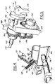
- a hold-down bracket 68 comprises a flat plate pivotally mounted to one end wall 48 of bath 26.
- Bracket 68 comprises a pair of coplanar parallel legs 70, 86 that extend upwardly from bath 26.
- An L-shaped arm 72 is adjustably mounted on leg 70 by means of a pair of mounting screws 74 extending through a pair of parallel slots 76 in arm 70.
- Arm 72 extends from plate 68 over bath 26.
- a block 77 is slidably mounted on arm 72 by means of a screw that extends through a longitudinal slot 75 oil arm 72.
- a pad 78 has a threaded shaft 80 that is adjustably positionable on block 77 by means of a nut 82. (A V-shaped pad 78a in FIG.
- Pad 78 thus holds container 22 on cradle 24.
- withdrawal of the container axially of the cradle removes the force of the container against bracket 68, so that the bracket is automatically pivoted by weight 90 from the position shown in FIGS. 2 and 3 to that shown in FIG. 4.
- Arm 72 is adjustably positionable on bracket 68, and weight 90 is adjustably positionable on bracket 68, to accommodate containers 22 of differing diameter and differing weight.
- Block 77 is adjustably positionable on arm 72 to accommodate containers of differing length.
- Spring 84 functions to urge pad 78 into sliding engagement with container 22 while preventing excessive clamping force. Sliding engagement between pad 78 and the outer surface of container 22 will be lubricated by the index oil, as will the sliding engagement between container 22 and cradle plates 60, 62.
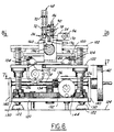
- Oil bath 26 is mounted on a flat oil pan 100 (FIGS. 2-3, 6 and 8-9).
- Oil pan 100 is mounted on an intermediate support plate 102 by a pair of laterally spaced linear bearings 104, which accommodate movement of pan 100 and bath 26 in the longitudinal direction of the bath - i.e., into the page in FIG. 6 - while preventing lateral motion of the bath - i.e., side to side in FIG. 6.
- Linear bearings 104 may be of any suitable character.
- Support plate 102 carries longitudinally spaced depending bearings 106 (FIGS. 8 and 9) that rotatably support a lead screw 108.
- Lead screw 108 is coupled by intermeshed spur gears 109, 111 to a handle 110 at the front of the apparatus.
- a leg 112 depends from oil pan 100 through a slot 114 in support plate 102 (FIG. 8), and terminates in a nut 115 that encompasses lead screw 108.
- the horizontal position of oil pan 100, and oil bath 26 carried thereby may be adjustably positioned longitudinally of support plate 102 by rotation of handle 110 and lead screw 108.
- a base plate 120 (FIGS. 2-3, 6-7 and 9) is supported by adjustable feet 122 above a work surface 124.
- Four lead screws 126 are supported on base plate 120 at the corners of a square (as best seen in FIG. 8) for rotation about parallel vertical axes.
- Lead screws 126 are rotatably received in four nuts 128 carried by plate 102 (FIGS. 2 and 6-9).
- Each lead screw 126 carries a spur gear 130 adjacent to base plate 120.
- the several gears 130 mesh with a central spur gear 132 that is rotatable on a vertical axis above the plane of base plate 120.
- Gear 132 is coupled by bevel gears 134, 136 to a horizontal shaft 138.
- Shaft 138 is rotatably supported by support plates 140 that extend upwardly from base plate 120, and is connected to a hand wheel 142.
- a second hand wheel 144 is coupled through a plate 146 on base plate 120 to intermeshed bevel gears 148, 150.
- Bevel gear 150 (FIG. 9) is connected by a shaft 151 to a spur gear 149 that is meshed with gear 132.
- lead screws 126 are rotated, and mounting plate 120 is raised and lowered, by rotation of either hand wheel 142 or 144.
- Wheel 142 provides for coarse adjustment of the vertical position of plate 102, while wheel 144 provides for fine adjustment of vertical position of plate 102.
- Light source 30 (FIG. 1), telephoto lens 41 (FIGS. 1 and 2) and camera 42 are mounted on work surface 124 by suitable mounting brackets separate from plate 120.
- FIGS. 2-3, 5-6 and 10 A chuck 160 for engaging and rotating the container is illustrated in FIGS. 2-3, 5-6 and 10.
- Chuck 160 includes a sleeve 162 of elastomeric material such as rubber.
- Sleeve 162 is captured between a pair of washers 164, 166.
- An elongated hollow sleeve 168 extends between washer 164 and a second washer 170.
- a rod 172 is affixed at one end to washer 166 and extends through the interior of sleeve 168.
- rod 172 On the remote side of washer 170, rod 172 is mounted by a pivot pin 174 to a chuck lever 176.
- Lever 176 has an elongated convex lobe 178 that slidably engages the opposing surface of washer 170 to cooperate with the axial elasticity of sleeve 162 to form a toggle clamp.
- sleeve 162 In the open position of the chuck and clamp, illustrated in FIG. 10, sleeve 162 is relaxed, and the handle of lever 176 extends axially outwardly.
- lever 176 is pivoted clockwise (in the orientation of FIG. 10), sleeve 162 is compressed between washers 164, 166, until the flat 180 of lobe 178 opposes washer 170, at which point the toggle clamp is locked in position.
- lever 176 To engage the finish of a container, and with lever 176 in the position of FIG.
- sleeve 162 and washer 166 are inserted into the open end of the container finish until the sealing surface of the container abuts washer 164.
- Lever 176 is then pivoted (clockwise in FIG. 10) to expand sleeve 162 radially outwardly and thereby firmly engage the inside diameter of the container finish.
- the container With the chuck firmly engaged with the container and lever 176 in the locked position of FIGS. 2 and 6, the container is now inserted into the apparatus by placement on cradle plates 62, 66 in abutment with bracket 68. Hold-down bracket 68 and pad 78 are thereby pivoted downwardly into engagement with the exterior of the container.
- Outer sleeve 168 is rested in the V-shaped slot 182 of a chuck mounting bracket 184 (FIGS. 2, 5 and 8) that extends upwardly from mounting plate 102.
- An arcuate clamp 186 (FIG. 5) is pivotally mounted on bracket 184, and has a radically projecting handle 188 by means of which clamp 186 maybe pivoted so as to capture chuck 160 on the assembly, as shown in FIG. 5.
- a spur gear 190 is adjustably positionable on chuck sleeve 168 for engagement in assembly with gears 192, 194 carried by bracket 184.
- Gear 194 is coupled to a dial indicator 196 carried on the outer face of bracket 184.
- an operator may rotate chuck 160, and simultaneously rotate container 22 within the test apparatus, with the degree of angular rotation being indicated to the operator at indicator 196.
- Elasticity of sleeve 162 in chuck 160 accommodates slight misalignment of the axis of the finish with respect to the axis of the container body, so that the body will continue to be held in fixed position against cradle 24 within bath 26.
- apparatus 20 is first set up with a container 22 of known characteristics.
- Chuck 160 is fitted into the finish of container 22, and container 22 is mounted on cradle 24 of bath 26.
- bracket 68 and arm 72 are pivoted downwardly so that pad 78 engages and holds container 22 on cradle 24.
- Chuck 160 is then placed on bracket 184, and clamp 186 is closed over chuck 160.
- light source 30, camera 32 and display 42 operating, and with oil 28 of bath 26 at desired temperature, vertical position of bath 26 is adjusted by means of adjustment wheels 142, 144 until display 42 shows intersection of the light beam with the area of interest at the container.
- Wheel 110 is then adjusted so that the beam will intersect the container at the desired axial position, and chuck 160 is rotated so that the beam intersects the container sidewall at the desired angular position.
- a new container 22 to be tested is then placed on chuck 160 and inserted into the apparatus.
- indices of refraction of the casing and core glass are sufficiently different (e.g., 1.520 versus 1.522), reflection from the casing/core interface may be employed, and polarizer 38 (FIG. 1) need not be used.
- polarizer 38 FIG. 1
- a slight refraction at the bottom tangent to the outer surface produces a dark line 200 against an otherwise bright background at camera 32 and display 42.
- the index mismatch at the casting/core interface produces a second dark line 204 because the light rays are reflected at the interface away from the camera.
- the casing layer produces the relatively thick bright area 202, and the core layer produces the relatively bright area 206.
- the thickness of the casing layer may readily be measured by comparing the width of area 202 to corresponding images of known thickness.
- FIG. 12 illustrates a potential problem in which the line 202c between the casing glass images 202a, 202b indicates possible layering within the casing glass layer.
- polarized light may be employed to establish a birefringence pattern indicative of the internally stressed casing glass layer thickness.
- Containers may be rapidly tested in a manufacturing environment for real-time quality control of the manufacturing process.
- Casing glass thickness may be measured at any desired position circumferentially of the container or axially of the container.
- the manual embodiment of the invention herein disclosed may be readily automated by suitably coupling the circumferential and axial adjustments to automated adjustment means such as electric motors. Very little indexing oil is lost during the measurement process.
- the compliant chuck mechanism of the present invention not only prevents entry of oil into the inside of the container, but also accommodates wobbles and misalignment of the container body with respect to the finish while maintaining integrity of the measurement process.
Abstract
Description
Claims (49)
- Apparatus for measuring glass layer thickness in a sidewall of a glass container ( 22) having a body and a finish, comprising:a bath (26) of oil (28) having an index of refraction matching that of the container sidewall,means (24) for engaging a container body in said bath so as to permit rotation of the body about its axis while restraining motion of the body laterally of its axis,means (160) for rotating the container on said engaging means,means (39) for directing light energy through said bath and tangentially through the sidewall of the container body in said bath on said engaging means so as to establish a pattern of light energy as a function of thickness of glass in the container body sidewall, andmeans (32) for determining glass thickness in the container sidewall as a function of said pattern of light energy.
- The apparatus set forth in claim 1 wherein said means (24) for engaging the container sidewall comprises mess (60, 62 or 60c, 62a) in said bath for sliding exterior engagement with the container sidewall, said sliding engagement being lubricated by said oil (28).
- The apparatus set forth in claim 2 wherein said means 60, 62 or 60c, 62a) in said bath comprises a cradle for externally engaging the sidewall of the container in said bath and slidably supporting the container in horizontal orientation in said bath.
- The apparatus set forth in claim 3 wherein said cradle comprises a pair of cradle plates (60, 62 or 60c, 62a) in said bath, each of said plates having a contoured edge for slidably externally supporting the sidewall of the container.
- The apparatus set forth in claim 4 wherein said means (24) for engaging the container sidewall further comprises means (50 - 66) for adjustably positioning at least one of said plates in said bath to accommodate containers of differing axial dimension.
- The apparatus set forth in claim 5 wherein said adjustably positioning means (50 - 66) comprises means for adjustably positioning both of said plates in said bath independently of each other.
- The apparatus set forth in claim 6 wherein said bath (26) comprises a pair of optically transparent sidewall (44, 46) that extend between spaced end walls (48), and wherein said adjustably positioning means (50 - 66) comprises a pair of screw rods (50, 52) that extend between and are rotatably supported by said end walls, each of said screw rods being operatively coupled to one of said cradle plates (60, 62 or 60a, 62a) for adjusting longitudinal position of the plate as a function of rotation of the screw rod.
- The apparatus set forth in claim 7 wherein said adjustably positioning means further comprises a pair of blocks (64, 66) each rotatably coupled to one of said screw rods, each of said cradle plates being removably mounted on one of said blocks.
- The apparatus set forth in claim 8 wherein said rods (50, 52) are mounted parallel to each other above and to one side of said bath (26), said cradle plates (60, 62 or 60a, 62a) extending laterally and downwardly into said bath.
- The apparatus set forth in claim 9 wherein said contoured edges of said plates (60, 62) are arcuate.
- The apparatus set forth in claim 9 wherein said contoured edges of said plates (60a, 62a) are V-shaped.
- The apparatus set forth in any preceding claim wherein said bath comprises a pair of optically transparent sidewalls (44, 46), a pair of spaced end walls (48) and a bottom wall that together contain a volume of said oil.
- The apparatus set forth in claim 12 further comprising means (68) positioned above said cradle for slidably externally engaging the sidewall of a container on said cradle while holding the container on the cradle against buoyancy of the container in the oil.
- The apparatus set forth in claim 13 wherein said holding means (68) comprise a bracket pivotally mounted on one of said end walls (48) and means on said bracket for engaging the sidewall of a container on said cradle.
- The apparatus set forth in claim 14 wherein said bracket (68) is positioned for engagement by the bottom of a container (22) as the container is placed on said cradle for pivoting said bracket and said means a said bracket into engagement with the container.
- The apparatus set forth in claim 15 wherein said means on said bracket comprises an arm (72) that extends from said bracket over a container on said cradle, and abutment means (78 or 78a) carried by said arm for engagement with the container.
- The apparatus set forth in claim 16 wherein said abutment means comprises an abutment pad (78) and a coil spring (84) for biasing said pad into engagement with the container.
- The apparatus set forth in claim 17 wherein said means on said bracket further comprises means (74) for adjusting position of said arm (72) on said bracket (68) for accommodating containers of differing diameter.
- The apparatus set forth in claim 18 wherein said holding means further comprises counterweight means (90) on said bracket for pivoting said bracket (68) and said arm (72) out of engagement with the container sidewall as the container is moved off of said cradle.
- The apparatus set forth in claim 19 wherein said holding means further comprises means (86, 88, 92) for adjusting position of said counterweight means on said bracket.
- The apparatus set forth in claim 12 wherein said light energy directing means 30) comprises a light source positioned on one side of said bath to direct light energy through said transparent sidewalls and through said bath, and wherein said identifying means (32) comprise light sensor means position to receive light energy transmitted through said bath.
- The apparatus set forth in claim 21 wherein said light source includes means (38) for polarizing light energy transmitted into said bath.
- The apparatus set forth in claim 22 wherein said polarizing means (38) comprises means for vertically polarizing said light energy.
- The apparatus set forth in claim 22 wherein said light source further includes means (40) for variably attenuating intensity of light energy of transmitted into said bath.
- The apparatus set forth in claim 21 further comprising means (100+) for adjusting position of said bath with respect to said light source.
- The apparatus set forth in claim 25 wherein said position-adjusting means (100+) comprises means for adjusting position of said bath in two directions perpendicular to said light source.
- The apparatus set forth in claim 26 wherein said position-adjusting means comprises a support plate (102), means (104 - 116) for horizontally adjustably positioning said bath on said support plate, and means (126 - 150) for adjustably vertically positioning said support plate.
- The apparatus set forth in claim 27 wherein said horizontally positioning means comprises linear hearing means (104) mounting said bath on said support plate (102), and means for moving said bath along said linear bearing means.
- The apparatus set forth in claim 28 wherein said means for moving said bath comprises a lead screw (108) coupled to said bath and means (110) for rotating said lead screw.
- The apparatus set forth in claim 29 wherein said lead screw (108) extends beneath said support plate (102), and said bath is coupled to said lead screw by means (112) extending through an elongated slot (114) in said support plate.
- The apparatus set forth in claim 29 wherein said vertically positioning means comprise a base plate (120), a plurality of lead screws (126) supporting said support plate (102) on said base plate, and means (128 - 150) for simultaneously rotating all of said plurality of lead screws.
- The apparatus set forth in claim 31 wherein said means for rotating said plurality of lead screws comprises a central gear (132) rotatably mounted on said base plate (120), a plurality of gears (130) surrounding said central gear and rotatably coupling said central gear to said lead screws (126), and means for rotating said central gear (134 - 150).
- The apparatus set forth in claim 32 wherein said means for rotating said central gear comprises means (142, 144) for rotating said central gear at differing ratios for course and fine adjustment of vertical position of said support plate.
- The apparatus set forth in any preceding claim wherein said means (160) for rotating the container comprises a chuck for releasably engaging the container finish and means for rotating said chuck.
- The apparatus set forth in claim 34 wherein said chuck includes means (162) for compliantly engaging the container finish to accommodate wobble of the finish with respect to the container body as the container is rotated.
- The apparatus set forth in claim 35 wherein said chuck comprises a sleeve (162) of elastic composition adapted to be received within the container finish, and means (164 - 180) for axially compressing and radially expanding said elastic sleeve to engage the inside diameter of the container finish.
- The apparatus set forth in claim 36 wherein said means for axially compressing and radially expanding said elastic sleeve comprise an elongated sleeve (168) coupled to one and of said elastic sleeve, a rod (172) coupled to an opposing end of said elastic sleeve and extending through said elongated sleeve, and a toggle clamp (178) coupled to said rod and said elongated sleeve at ends thereof remote from said elastic sleeve.
- The apparatus set forth in claim 37 wherein said chuck (160) is removably positionable and manually rotatable on said apparatus.
- The apparatus set forth in claim 38 further comprising means (196) operatively coupled to said chuck (160) when said chuck is positioned on said apparatus for indicating angular position of said chuck.
- The apparatus set forth in any preceding claim wherein said identifying means (32) includes means (42) for displaying to an operator glass layer thickness in the container sidewall.
- The apparatus set forth in any preceding claim 3 further comprising means (34) for controlling temperature of said oil in said bath.
- The apparatus set forth in claim 41 wherein said temperature-controlling means comprises means (36) for circulating the oil externally of the bath.
- The apparatus set forth in any preceding claim wherein said energy-directing means comprises means (38) for directing polarized light energy tangentially through the sidewall of the container body in said bath to establish a birefringence pattern of light energy as a function of stress in the container body sidewall, and wherein said thickness-determining means (32) is responsive to said birefringence pattern to determine thickness of the layer containing such stress.
- For use in conjunction with a glass container (22) having a finish and a body consisting of multiple layers of glass of differing composition, a method of measuring thickness of said at least one layer comprising the steps of:(a) rotating the finish of the container while structurally supporting the container body so that the body rotates about its axis independent of the axis of rotation of the finish,(b) directing light energy tangentially through the container body so as to establish a pattern of light energy as a function of thickness of said at least one layer, and(c) determining thickness of said at least one layer as a function of said pattern of light energy.
- The method set forth in claim 44 wherein said compositions are such that two of such layers have differing indices of refraction, and wherein said light pattern includes information indicative of reflection of light energy from the interface between said layers.
- The method set forth in claim 44 or 45 wherein said step (b) comprises the step of polarizing the light energy in a direction perpendicular to said axis of rotation, such that said light pattern comprises a birefringence pattern of light energy as a function of residual stress in said one layer.
- The method set forth in claim 44, 45 or 46 wherein said axis of rotation is horizontal.
- The method set forth in claim 44, 45, 46 or 47 comprising the additional step of: (d) variably attenuating said light energy directed through the container body in said step (b) to accommodate glasses of differing opacity.
- The method set forth in any one of claims 44-48 wherein said step (a) is carried out by positioning the container body on cradle in a bath of oil that matches the index of refraction of the glass container outer surface.
Applications Claiming Priority (2)
| Application Number | Priority Date | Filing Date | Title |
|---|---|---|---|
| US09/058,180 US6133999A (en) | 1998-04-10 | 1998-04-10 | Measuring sidewall thickness of glass containers |
| US58180 | 1998-04-10 |
Publications (2)
| Publication Number | Publication Date |
|---|---|
| EP0949482A2 true EP0949482A2 (en) | 1999-10-13 |
| EP0949482A3 EP0949482A3 (en) | 2002-04-03 |
Family
ID=22015195
Family Applications (1)
| Application Number | Title | Priority Date | Filing Date |
|---|---|---|---|
| EP99106750A Withdrawn EP0949482A3 (en) | 1998-04-10 | 1999-04-03 | Measuring sidewall thickness of glass containers |
Country Status (16)
| Country | Link |
|---|---|
| US (1) | US6133999A (en) |
| EP (1) | EP0949482A3 (en) |
| JP (1) | JP3620990B2 (en) |
| CN (1) | CN1157588C (en) |
| AR (1) | AR019043A1 (en) |
| AU (1) | AU749028B2 (en) |
| BR (1) | BR9902360A (en) |
| CA (1) | CA2267873A1 (en) |
| CO (1) | CO4820448A1 (en) |
| CZ (1) | CZ125999A3 (en) |
| EE (1) | EE04066B1 (en) |
| HU (1) | HU225338B1 (en) |
| PE (1) | PE20000663A1 (en) |
| PL (1) | PL191232B1 (en) |
| RU (1) | RU2227270C2 (en) |
| ZA (1) | ZA992637B (en) |
Cited By (1)
| Publication number | Priority date | Publication date | Assignee | Title |
|---|---|---|---|---|
| EP2188108B2 (en) † | 2007-09-21 | 2023-02-22 | KHS GmbH | Method for blow-molding containers |
Families Citing this family (15)
| Publication number | Priority date | Publication date | Assignee | Title |
|---|---|---|---|---|
| DE19930536C2 (en) * | 1999-06-28 | 2001-07-05 | Manfred Kuhnke | Device for measuring a box cross-section |
| US6778285B1 (en) * | 2000-01-21 | 2004-08-17 | Wafertech, Inc. | Automatic in situ pellicle height measurement system |
| US6520049B2 (en) | 2001-04-27 | 2003-02-18 | Hallmark Cards Incorporated | Method of digitizing emboss dies and the like |
| DE10257422A1 (en) * | 2002-12-09 | 2004-07-08 | Specialty Minerals Michigan Inc., Bingham Farms | Method for positioning a measuring device that emits and receives optical radiation, for measuring wear on the lining of a container |
| US20050075038A1 (en) * | 2003-02-12 | 2005-04-07 | Kyne Sean P. | Packaging for toy and lithophane combinations |
| US7148961B1 (en) | 2004-11-10 | 2006-12-12 | Owens-Brockway Glass Container Inc. | Container sidewall inspection |
| EP2261633A1 (en) * | 2009-06-10 | 2010-12-15 | Becton Dickinson France | Supporting device for a transparent article and method for putting said article under compression |
| EP2284481A1 (en) * | 2009-08-05 | 2011-02-16 | Emhart Glass S.A. | Glass container wall thickness measurement using fluorescence |
| EP2282186B1 (en) * | 2009-08-05 | 2015-09-09 | Emhart Glass S.A. | Glass container stress measurement using fluorescence |
| US9109879B2 (en) | 2012-02-29 | 2015-08-18 | Corning Incorporated | Systems for and methods of characterizing the thickness profile of laminated glass structures |
| FR2997181B1 (en) * | 2012-10-18 | 2014-12-12 | Msc & Sgcc | INSTALLATION FOR MEASURING THE THICKNESS OF THE WALL OF CONTAINERS |
| TWI700473B (en) | 2014-06-04 | 2020-08-01 | 美商康寧公司 | Method and system for measuring thickness of glass article |
| TWI509215B (en) * | 2015-07-02 | 2015-11-21 | Ta Jen Kuo | A high accuracy apparatus and method of photoelectric glass substrate in real-time identification |
| GB201601960D0 (en) * | 2016-02-03 | 2016-03-16 | Glaxosmithkline Biolog Sa | Novel device |
| US10871400B2 (en) * | 2018-08-27 | 2020-12-22 | Corning Incorporated | Retardation profile for stress characterization of tubing |
Citations (3)
| Publication number | Priority date | Publication date | Assignee | Title |
|---|---|---|---|---|
| US3773420A (en) * | 1972-02-28 | 1973-11-20 | Anchor Hocking Corp | Apparatus for measuring the thickness of a metal oxide coating on a glass article |
| US3989380A (en) * | 1975-04-02 | 1976-11-02 | Dominion Glass Company Limited | Apparatus for detecting flaws in transparent containers |
| US5305081A (en) * | 1992-08-27 | 1994-04-19 | Constar Plastics Inc. | Bottle stress analysis system |
Family Cites Families (11)
| Publication number | Priority date | Publication date | Assignee | Title |
|---|---|---|---|---|
| US3302786A (en) * | 1964-09-29 | 1967-02-07 | Owens Illinois Inc | Inspecting glass containers with lasers |
| US4207000A (en) * | 1978-02-27 | 1980-06-10 | Rca Corporation | Waveguide method for determining stress at the convex surface of a body |
| US4291271A (en) * | 1979-11-01 | 1981-09-22 | Phillips Petroleum Company | Method for determining pore size distribution and fluid distribution in porous media |
| US4459023A (en) * | 1981-06-30 | 1984-07-10 | Kirin Beer Kabushiki Kaisha | Electro-optic inspection system for transparent or semitransparent containers |
| JPS59114445A (en) * | 1982-12-21 | 1984-07-02 | Yamamura Glass Kk | Apparatus for detecting defect of transparent body |
| JPS603542A (en) * | 1983-06-21 | 1985-01-09 | Mitsubishi Electric Corp | Bottle inspecting device |
| US4601395A (en) * | 1984-04-23 | 1986-07-22 | Owens-Illinois, Inc. | Inspecting and sorting of glass containers |
| DE3503086C1 (en) * | 1985-01-30 | 1986-06-19 | Dipl.-Ing. Bruno Richter GmbH & Co. Elektronische Betriebskontroll-Geräte KG, 8602 Stegaurach | Method and device for measuring the wall thickness of transparent objects |
| US4668086A (en) * | 1985-05-20 | 1987-05-26 | Salomon Redner | Stress and strain measuring apparatus and method |
| GB2265458A (en) * | 1992-03-28 | 1993-09-29 | Rover Group | Multi-wavelength photoelastic stress analysis |
| US5291271A (en) * | 1992-08-19 | 1994-03-01 | Owens-Brockway Glass Container Inc. | Measurement of transparent container wall thickness |
-
1998
- 1998-04-10 US US09/058,180 patent/US6133999A/en not_active Expired - Fee Related
-
1999
- 1999-03-31 CA CA002267873A patent/CA2267873A1/en not_active Abandoned
- 1999-04-01 HU HU9900845A patent/HU225338B1/en not_active IP Right Cessation
- 1999-04-03 EP EP99106750A patent/EP0949482A3/en not_active Withdrawn
- 1999-04-08 AU AU23662/99A patent/AU749028B2/en not_active Ceased
- 1999-04-09 PL PL332448A patent/PL191232B1/en unknown
- 1999-04-09 PE PE1999000291A patent/PE20000663A1/en not_active Application Discontinuation
- 1999-04-09 BR BR9902360-1A patent/BR9902360A/en not_active Application Discontinuation
- 1999-04-09 CO CO99021080A patent/CO4820448A1/en unknown
- 1999-04-09 EE EEP199900130A patent/EE04066B1/en not_active IP Right Cessation
- 1999-04-09 RU RU99107129/28A patent/RU2227270C2/en not_active IP Right Cessation
- 1999-04-09 ZA ZA9902637A patent/ZA992637B/en unknown
- 1999-04-09 CZ CZ991259A patent/CZ125999A3/en unknown
- 1999-04-09 AR ARP990101652A patent/AR019043A1/en active IP Right Grant
- 1999-04-09 CN CNB991060512A patent/CN1157588C/en not_active Expired - Fee Related
- 1999-04-12 JP JP10367799A patent/JP3620990B2/en not_active Expired - Fee Related
Patent Citations (3)
| Publication number | Priority date | Publication date | Assignee | Title |
|---|---|---|---|---|
| US3773420A (en) * | 1972-02-28 | 1973-11-20 | Anchor Hocking Corp | Apparatus for measuring the thickness of a metal oxide coating on a glass article |
| US3989380A (en) * | 1975-04-02 | 1976-11-02 | Dominion Glass Company Limited | Apparatus for detecting flaws in transparent containers |
| US5305081A (en) * | 1992-08-27 | 1994-04-19 | Constar Plastics Inc. | Bottle stress analysis system |
Cited By (1)
| Publication number | Priority date | Publication date | Assignee | Title |
|---|---|---|---|---|
| EP2188108B2 (en) † | 2007-09-21 | 2023-02-22 | KHS GmbH | Method for blow-molding containers |
Also Published As
| Publication number | Publication date |
|---|---|
| AR019043A1 (en) | 2001-12-26 |
| CA2267873A1 (en) | 1999-10-10 |
| HUP9900845A3 (en) | 2002-02-28 |
| JPH11325837A (en) | 1999-11-26 |
| ZA992637B (en) | 1999-10-08 |
| CN1157588C (en) | 2004-07-14 |
| HU225338B1 (en) | 2006-09-28 |
| HUP9900845A2 (en) | 1999-11-29 |
| PL332448A1 (en) | 1999-10-11 |
| EP0949482A3 (en) | 2002-04-03 |
| EE04066B1 (en) | 2003-06-16 |
| JP3620990B2 (en) | 2005-02-16 |
| CZ125999A3 (en) | 1999-10-13 |
| HU9900845D0 (en) | 1999-06-28 |
| CN1233747A (en) | 1999-11-03 |
| RU2227270C2 (en) | 2004-04-20 |
| BR9902360A (en) | 2000-02-01 |
| AU749028B2 (en) | 2002-06-13 |
| PL191232B1 (en) | 2006-03-31 |
| US6133999A (en) | 2000-10-17 |
| PE20000663A1 (en) | 2000-08-02 |
| CO4820448A1 (en) | 1999-07-28 |
| AU2366299A (en) | 1999-10-21 |
| EE9900130A (en) | 1999-12-15 |
Similar Documents
| Publication | Publication Date | Title |
|---|---|---|
| US6133999A (en) | Measuring sidewall thickness of glass containers | |
| CA2186719C (en) | Lens parameter measurement using optical sectioning | |
| US20100128267A1 (en) | Automatic brewster angle refractometer | |
| RU99107129A (en) | MEASURING THICKNESS OF THE SIDE WALL OF A GLASS VESSEL | |
| CN111397518A (en) | Optical lens detection device | |
| EP3612820B1 (en) | Improved method for analysing a gemstone | |
| US4072428A (en) | Inspecting and measuring of soft contact lenses | |
| CN211784852U (en) | Substrate glass detection device | |
| CN200965465Y (en) | Optical glass roughness real-time detector | |
| CA2679558C (en) | A method for evaluation of a gemstone | |
| US4991967A (en) | Scratch depth measuring instrument and method | |
| CN109596036A (en) | A kind of glass sample right angle test device and its test method | |
| MXPA99003279A (en) | Measurement of the thick wall of the side wall of vid containers | |
| KR100932740B1 (en) | Lens shape inspection device | |
| CN214538473U (en) | Optical lens detection device with alarm mechanism | |
| US2418463A (en) | Crystal analysis apparatus | |
| CN218496054U (en) | Utensil is examined to commentaries on classics mirror support | |
| EP0101375A1 (en) | Method and apparatus for determining without making contact the roughness of a surface | |
| CN214372196U (en) | Roundness measuring device for large-size bearing retainer | |
| CN217059268U (en) | Measuring device for optical lens processing | |
| CN219142687U (en) | Surface detection device of optical part | |
| CN220356401U (en) | Detection support for optical instrument | |
| Gorycki | Simple and rapid block face alignment methods for the ultramicrotome | |
| KR890001151Y1 (en) | Measuring arrangements | |
| CN113865828A (en) | Special calibrating device for reading microscope |
Legal Events
| Date | Code | Title | Description |
|---|---|---|---|
| PUAI | Public reference made under article 153(3) epc to a published international application that has entered the european phase |
Free format text: ORIGINAL CODE: 0009012 |
|
| AK | Designated contracting states |
Kind code of ref document: A2 Designated state(s): AT BE CH CY DE DK ES FI FR GB GR IE IT LI LU MC NL PT SE Kind code of ref document: A2 Designated state(s): AT BE CH DE DK ES FI FR GB GR IT LI NL PT SE |
|
| AX | Request for extension of the european patent |
Free format text: AL;LT;LV;MK;RO;SI |
|
| PUAL | Search report despatched |
Free format text: ORIGINAL CODE: 0009013 |
|
| AK | Designated contracting states |
Kind code of ref document: A3 Designated state(s): AT BE CH CY DE DK ES FI FR GB GR IE IT LI LU MC NL PT SE |
|
| AX | Request for extension of the european patent |
Free format text: AL;LT;LV;MK;RO;SI |
|
| 17P | Request for examination filed |
Effective date: 20020905 |
|
| AKX | Designation fees paid |
Free format text: AT BE CH DE DK ES FI FR GB GR IT LI NL PT SE |
|
| RAP1 | Party data changed (applicant data changed or rights of an application transferred) |
Owner name: OWENS-BROCKWAY GLASS CONTAINER INC. |
|
| 17Q | First examination report despatched |
Effective date: 20071115 |
|
| STAA | Information on the status of an ep patent application or granted ep patent |
Free format text: STATUS: THE APPLICATION IS DEEMED TO BE WITHDRAWN |
|
| 18D | Application deemed to be withdrawn |
Effective date: 20080326 |