EP0948947A2 - Hydraulisches Prothesengelenk - Google Patents
Hydraulisches Prothesengelenk Download PDFInfo
- Publication number
- EP0948947A2 EP0948947A2 EP99302709A EP99302709A EP0948947A2 EP 0948947 A2 EP0948947 A2 EP 0948947A2 EP 99302709 A EP99302709 A EP 99302709A EP 99302709 A EP99302709 A EP 99302709A EP 0948947 A2 EP0948947 A2 EP 0948947A2
- Authority
- EP
- European Patent Office
- Prior art keywords
- hydraulic
- joint
- agent
- upper section
- prosthetic joint
- Prior art date
- Legal status (The legal status is an assumption and is not a legal conclusion. Google has not performed a legal analysis and makes no representation as to the accuracy of the status listed.)
- Withdrawn
Links
- 210000000544 articulatio talocruralis Anatomy 0.000 claims abstract description 32
- 229920001296 polysiloxane Polymers 0.000 claims abstract description 24
- 239000003795 chemical substances by application Substances 0.000 description 52
- 239000012530 fluid Substances 0.000 description 17
- 210000002683 foot Anatomy 0.000 description 14
- 210000001503 joint Anatomy 0.000 description 11
- 239000007787 solid Substances 0.000 description 10
- 239000002245 particle Substances 0.000 description 8
- 229920002379 silicone rubber Polymers 0.000 description 8
- 239000004945 silicone rubber Substances 0.000 description 8
- 239000002131 composite material Substances 0.000 description 7
- 238000010276 construction Methods 0.000 description 7
- 239000003921 oil Substances 0.000 description 6
- 239000004215 Carbon black (E152) Substances 0.000 description 5
- 210000003423 ankle Anatomy 0.000 description 5
- 238000006073 displacement reaction Methods 0.000 description 5
- 229930195733 hydrocarbon Natural products 0.000 description 5
- 150000002430 hydrocarbons Chemical class 0.000 description 5
- 238000013016 damping Methods 0.000 description 3
- 230000000694 effects Effects 0.000 description 3
- 230000006835 compression Effects 0.000 description 2
- 238000007906 compression Methods 0.000 description 2
- 239000002537 cosmetic Substances 0.000 description 2
- 229920001971 elastomer Polymers 0.000 description 2
- 239000007788 liquid Substances 0.000 description 2
- 238000003754 machining Methods 0.000 description 2
- 239000006249 magnetic particle Substances 0.000 description 2
- 238000004519 manufacturing process Methods 0.000 description 2
- 239000011159 matrix material Substances 0.000 description 2
- 238000004088 simulation Methods 0.000 description 2
- 208000004067 Flatfoot Diseases 0.000 description 1
- 238000005452 bending Methods 0.000 description 1
- 230000009286 beneficial effect Effects 0.000 description 1
- 230000015556 catabolic process Effects 0.000 description 1
- 230000005021 gait Effects 0.000 description 1
- 238000010438 heat treatment Methods 0.000 description 1
- 239000010720 hydraulic oil Substances 0.000 description 1
- 230000008407 joint function Effects 0.000 description 1
- 210000000629 knee joint Anatomy 0.000 description 1
- 210000002414 leg Anatomy 0.000 description 1
- 230000004048 modification Effects 0.000 description 1
- 238000012986 modification Methods 0.000 description 1
- 238000013021 overheating Methods 0.000 description 1
- 238000005192 partition Methods 0.000 description 1
- 238000007789 sealing Methods 0.000 description 1
- 238000000638 solvent extraction Methods 0.000 description 1
- 239000000126 substance Substances 0.000 description 1
Images


Classifications
-
- A—HUMAN NECESSITIES
- A61—MEDICAL OR VETERINARY SCIENCE; HYGIENE
- A61F—FILTERS IMPLANTABLE INTO BLOOD VESSELS; PROSTHESES; DEVICES PROVIDING PATENCY TO, OR PREVENTING COLLAPSING OF, TUBULAR STRUCTURES OF THE BODY, e.g. STENTS; ORTHOPAEDIC, NURSING OR CONTRACEPTIVE DEVICES; FOMENTATION; TREATMENT OR PROTECTION OF EYES OR EARS; BANDAGES, DRESSINGS OR ABSORBENT PADS; FIRST-AID KITS
- A61F2/00—Filters implantable into blood vessels; Prostheses, i.e. artificial substitutes or replacements for parts of the body; Appliances for connecting them with the body; Devices providing patency to, or preventing collapsing of, tubular structures of the body, e.g. stents
- A61F2/50—Prostheses not implantable in the body
- A61F2/60—Artificial legs or feet or parts thereof
- A61F2/66—Feet; Ankle joints
- A61F2/6607—Ankle joints
-
- A—HUMAN NECESSITIES
- A61—MEDICAL OR VETERINARY SCIENCE; HYGIENE
- A61F—FILTERS IMPLANTABLE INTO BLOOD VESSELS; PROSTHESES; DEVICES PROVIDING PATENCY TO, OR PREVENTING COLLAPSING OF, TUBULAR STRUCTURES OF THE BODY, e.g. STENTS; ORTHOPAEDIC, NURSING OR CONTRACEPTIVE DEVICES; FOMENTATION; TREATMENT OR PROTECTION OF EYES OR EARS; BANDAGES, DRESSINGS OR ABSORBENT PADS; FIRST-AID KITS
- A61F2/00—Filters implantable into blood vessels; Prostheses, i.e. artificial substitutes or replacements for parts of the body; Appliances for connecting them with the body; Devices providing patency to, or preventing collapsing of, tubular structures of the body, e.g. stents
- A61F2/50—Prostheses not implantable in the body
- A61F2/68—Operating or control means
- A61F2/74—Operating or control means fluid, i.e. hydraulic or pneumatic
-
- A—HUMAN NECESSITIES
- A61—MEDICAL OR VETERINARY SCIENCE; HYGIENE
- A61F—FILTERS IMPLANTABLE INTO BLOOD VESSELS; PROSTHESES; DEVICES PROVIDING PATENCY TO, OR PREVENTING COLLAPSING OF, TUBULAR STRUCTURES OF THE BODY, e.g. STENTS; ORTHOPAEDIC, NURSING OR CONTRACEPTIVE DEVICES; FOMENTATION; TREATMENT OR PROTECTION OF EYES OR EARS; BANDAGES, DRESSINGS OR ABSORBENT PADS; FIRST-AID KITS
- A61F2/00—Filters implantable into blood vessels; Prostheses, i.e. artificial substitutes or replacements for parts of the body; Appliances for connecting them with the body; Devices providing patency to, or preventing collapsing of, tubular structures of the body, e.g. stents
- A61F2/50—Prostheses not implantable in the body
- A61F2002/5003—Prostheses not implantable in the body having damping means, e.g. shock absorbers
-
- A—HUMAN NECESSITIES
- A61—MEDICAL OR VETERINARY SCIENCE; HYGIENE
- A61F—FILTERS IMPLANTABLE INTO BLOOD VESSELS; PROSTHESES; DEVICES PROVIDING PATENCY TO, OR PREVENTING COLLAPSING OF, TUBULAR STRUCTURES OF THE BODY, e.g. STENTS; ORTHOPAEDIC, NURSING OR CONTRACEPTIVE DEVICES; FOMENTATION; TREATMENT OR PROTECTION OF EYES OR EARS; BANDAGES, DRESSINGS OR ABSORBENT PADS; FIRST-AID KITS
- A61F2/00—Filters implantable into blood vessels; Prostheses, i.e. artificial substitutes or replacements for parts of the body; Appliances for connecting them with the body; Devices providing patency to, or preventing collapsing of, tubular structures of the body, e.g. stents
- A61F2/50—Prostheses not implantable in the body
- A61F2002/5003—Prostheses not implantable in the body having damping means, e.g. shock absorbers
- A61F2002/5006—Dampers, e.g. hydraulic damper
-
- A—HUMAN NECESSITIES
- A61—MEDICAL OR VETERINARY SCIENCE; HYGIENE
- A61F—FILTERS IMPLANTABLE INTO BLOOD VESSELS; PROSTHESES; DEVICES PROVIDING PATENCY TO, OR PREVENTING COLLAPSING OF, TUBULAR STRUCTURES OF THE BODY, e.g. STENTS; ORTHOPAEDIC, NURSING OR CONTRACEPTIVE DEVICES; FOMENTATION; TREATMENT OR PROTECTION OF EYES OR EARS; BANDAGES, DRESSINGS OR ABSORBENT PADS; FIRST-AID KITS
- A61F2/00—Filters implantable into blood vessels; Prostheses, i.e. artificial substitutes or replacements for parts of the body; Appliances for connecting them with the body; Devices providing patency to, or preventing collapsing of, tubular structures of the body, e.g. stents
- A61F2/50—Prostheses not implantable in the body
- A61F2002/5016—Prostheses not implantable in the body adjustable
- A61F2002/503—Prostheses not implantable in the body adjustable for adjusting elasticity, flexibility, spring rate or mechanical tension
-
- A—HUMAN NECESSITIES
- A61—MEDICAL OR VETERINARY SCIENCE; HYGIENE
- A61F—FILTERS IMPLANTABLE INTO BLOOD VESSELS; PROSTHESES; DEVICES PROVIDING PATENCY TO, OR PREVENTING COLLAPSING OF, TUBULAR STRUCTURES OF THE BODY, e.g. STENTS; ORTHOPAEDIC, NURSING OR CONTRACEPTIVE DEVICES; FOMENTATION; TREATMENT OR PROTECTION OF EYES OR EARS; BANDAGES, DRESSINGS OR ABSORBENT PADS; FIRST-AID KITS
- A61F2/00—Filters implantable into blood vessels; Prostheses, i.e. artificial substitutes or replacements for parts of the body; Appliances for connecting them with the body; Devices providing patency to, or preventing collapsing of, tubular structures of the body, e.g. stents
- A61F2/50—Prostheses not implantable in the body
- A61F2002/5016—Prostheses not implantable in the body adjustable
- A61F2002/5032—Prostheses not implantable in the body adjustable for adjusting fluid pressure
-
- A—HUMAN NECESSITIES
- A61—MEDICAL OR VETERINARY SCIENCE; HYGIENE
- A61F—FILTERS IMPLANTABLE INTO BLOOD VESSELS; PROSTHESES; DEVICES PROVIDING PATENCY TO, OR PREVENTING COLLAPSING OF, TUBULAR STRUCTURES OF THE BODY, e.g. STENTS; ORTHOPAEDIC, NURSING OR CONTRACEPTIVE DEVICES; FOMENTATION; TREATMENT OR PROTECTION OF EYES OR EARS; BANDAGES, DRESSINGS OR ABSORBENT PADS; FIRST-AID KITS
- A61F2/00—Filters implantable into blood vessels; Prostheses, i.e. artificial substitutes or replacements for parts of the body; Appliances for connecting them with the body; Devices providing patency to, or preventing collapsing of, tubular structures of the body, e.g. stents
- A61F2/50—Prostheses not implantable in the body
- A61F2002/5038—Hinged joint, e.g. with transverse axle restricting the movement
- A61F2002/5043—Hinged joint, e.g. with transverse axle restricting the movement with rotation-limiting stops, e.g. projections or recesses
-
- A—HUMAN NECESSITIES
- A61—MEDICAL OR VETERINARY SCIENCE; HYGIENE
- A61F—FILTERS IMPLANTABLE INTO BLOOD VESSELS; PROSTHESES; DEVICES PROVIDING PATENCY TO, OR PREVENTING COLLAPSING OF, TUBULAR STRUCTURES OF THE BODY, e.g. STENTS; ORTHOPAEDIC, NURSING OR CONTRACEPTIVE DEVICES; FOMENTATION; TREATMENT OR PROTECTION OF EYES OR EARS; BANDAGES, DRESSINGS OR ABSORBENT PADS; FIRST-AID KITS
- A61F2/00—Filters implantable into blood vessels; Prostheses, i.e. artificial substitutes or replacements for parts of the body; Appliances for connecting them with the body; Devices providing patency to, or preventing collapsing of, tubular structures of the body, e.g. stents
- A61F2/50—Prostheses not implantable in the body
- A61F2002/5067—Prostheses not implantable in the body having rolling elements between articulating surfaces
- A61F2002/5069—Ball bearings
-
- A—HUMAN NECESSITIES
- A61—MEDICAL OR VETERINARY SCIENCE; HYGIENE
- A61F—FILTERS IMPLANTABLE INTO BLOOD VESSELS; PROSTHESES; DEVICES PROVIDING PATENCY TO, OR PREVENTING COLLAPSING OF, TUBULAR STRUCTURES OF THE BODY, e.g. STENTS; ORTHOPAEDIC, NURSING OR CONTRACEPTIVE DEVICES; FOMENTATION; TREATMENT OR PROTECTION OF EYES OR EARS; BANDAGES, DRESSINGS OR ABSORBENT PADS; FIRST-AID KITS
- A61F2/00—Filters implantable into blood vessels; Prostheses, i.e. artificial substitutes or replacements for parts of the body; Appliances for connecting them with the body; Devices providing patency to, or preventing collapsing of, tubular structures of the body, e.g. stents
- A61F2/50—Prostheses not implantable in the body
- A61F2002/5096—Ball-and-socket joints
- A61F2002/5098—Ball-and-socket joints with rotation-limiting means
Definitions
- the present invention relates to prosthetic joints.
- Prosthetic joints are commonly hydraulic, so that the movement of the joint about its axis, or the movement of parts of the joint relative to each other, is controlled by the damping properties of a viscous hydraulic fluid.
- the restricted viscous displacement of the fluid provides the control, and this may operate in conjunction with elastic elements such as springs or rubber components. Hence viscous and elastic properties can be provided, which is desirable for acceptable simulation of joint function.
- the hydraulic fluid is typically a hydrocarbon hydraulic oil, having a low viscosity, typically below 50 centistokes.
- a hydrocarbon hydraulic oil having a low viscosity, typically below 50 centistokes.
- the joint To achieve sufficient viscous effect from such a substance it is necessary for the joint to be relatively bulky, which is undesirable, for cosmetic reasons, for example. Smaller joint constructions are not powerful enough, and are also subject to overheating of the oil due to movement in a confined space.
- the oil lacks an elastic response, which makes it suitable for some prosthetic applications, such as artificial knee joints, but less suitable for other types of artificial joint, such as ankles, which ideally are provided with some elastic properties to enable the joint to be self-realigning and hence resume its original shape and position.
- An aim of the present invention is to address these shortcomings.
- the present invention is directed to a hydraulic prosthetic joint in which the hydraulic agent is silicone-based.
- Silicone can provide a viscoelastic response which is well-suited to give natural control and movement of a prosthetic joint
- the hydraulic agent is a silicone fluid.
- High viscosity can be achieved with a silicone fluid, which offers a number of advantages, including the use of more compact joint constructions, and lower machining tolerance requirements in joint manufacture.
- the silicone fluid has a viscosity of at least 10,000 centipoise.
- the hydraulic agent is a composite comprising silicone rubber solid and silicone fluid.
- the silicone rubber solid provides a primarily elastic response and the silicone fluid provides a primarily high viscosity response, so that an overall viscoelastic response can be achieved, and tailored to meet the demands of a specific joint.
- the composite hydraulic agent comprises silicone rubber solid particles suspended in a silicone fluid matrix.
- a silicone fluid matrix Such a construction emphasises the viscosity of the viscoelastic response.
- the smallest dimension of the particles is not less than 0.3 mm.
- the composite hydraulic agent comprises porous flexible silicone rubber solid filled with silicone fluid.
- Such a construction emphasises the elasticity of the viscoelastic response.
- the hydraulic agent further comprises magnetic particles. This offers the advantage that the flow of the hydraulic agent can be controlled by the application of a magnetic field to align the magnetic particles, which can increase the dynamic viscosity.
- a second aspect of the present invention is directed to a hydraulic prosthetic joint comprising a base section, an upper section pivotally mounted to the base section via pivot means, and a hydraulic chamber defined by the upper section and the base section and filled with a hydraulic agent.
- This construction is suitable for a variety of joints.
- the prosthetic joint further comprises a body disposed within the hydraulic chamber. This has the effect of partly partitioning the hydraulic chamber so that the hydraulic agent must flow around the body.
- the body is attached to the base section such that a space is provided between the upper surface of the body and the underside of the upper section.
- the space acts as a hydraulic passage so that the hydraulic agent can flow between different parts of the hydraulic chamber via the passage.
- the body is an upright member situated substantially centrally in the hydraulic chamber. This provides a broadly symmetric distribution of hydraulic agent within the hydraulic chamber so that movement of the prosthetic joint is well-balanced.
- the pivot means is a ball joint.
- Ball joints provide a simple, low friction, low wear pivot means.
- the ball joint uses ball bearings.
- the base section is provided with a shoulder on its upper edge to contain the upper section and define its pivotal movement.
- a hydraulic seal is disposed between the upper section and the base section.
- the upper section is provided with a projecting lip on its lower surface. This increase the area acting on the hydraulic agent and hence increases displacement and compression of the hydraulic agent during pivoting of the ankle joint, thus producing a greater response.
- the hydraulic prosthetic joint is further provided with an externally adjustable valve to control flow of the hydraulic agent over the top of the body.
- an externally adjustable valve to control flow of the hydraulic agent over the top of the body.
- the hydraulic prosthetic joint is further provided with a manual lock to constrain the permitted pivotal movement.
- a manual lock to constrain the permitted pivotal movement.
- the body has an asymmetric profile in a plane substantially orthogonal to the pivot axis of the upper section.
- the upper section can pivot through a greater angle in one direction than in the other direction with respect to the position equivalent to the joint being at rest.
- This feature can simulate the movement of a real joint, in which movement in one direction is greater than in another direction.
- the hydraulic prosthetic joint is an ankle joint.
- the base section of the ankle joint is adapted for connection to a prosthetic foot.
- the upper section of the ankle joint is adapted for connection to a lower leg.
- the greater pivot angle corresponds to movement of the prosthetic ankle producing plantarflexion of a prosthetic foot.
- This construction allows simulation of a real ankle joint, in which plantarflexion is greater than dorsiflexion.
- the lower surface of the upper section is a slanted distal plane. This construction provides the desired difference in plantarflexion and dorsiflexion without the need for additional components within the joint.
- the body has a profile which causes less resistance to flow of the hydraulic agent for rotation of the upper section in the direction of rotation corresponding to plantarflexion of a prosthetic foot. This compensates for a net dorsiflexion moment resulting from the asymmetry of the foot, and hence improves stability.
- the upper section is free to tilt from side to side. This provides the advantage that the user can more easily negotiate cambers and uneven ground.
- the underside of the upper section is provided with a protrusion and the upper surface of the body is provided with a co-operating recess such that the recess is of sufficient size to permit sideways movement of the protrusion within it.
- a configuration allows the desired tilting movement but constrains it to an appropriate angle by restricting the movement of the upper section in relation to the base member.
- the underside of the upper section is provided with a recess and the upper surface of the body is provided with a co-operating protrusion such that the recess is of sufficient size to permit sideways movement of the protrusion within it.
- co-operating protrusion and recess further permit slight rotation of the upper section with respect to the base section about the vertical axis of the prosthetic ankle joint. This simulates the rotation of a foot about an ankle.
- the hydraulic agent is silicone-based.
- the viscoelastic response of the hydraulic agent is well-suited to an ankle joint, and provides self-alignment of a prosthetic foot used in conjunction with the ankle joint.
- a third aspect of the present invention is directed to a hydraulic prosthetic joint which is a rotary joint comprising a housing defining a hydraulic chamber and a rotor member disposed within the hydraulic chamber and free to rotate therein such that the angle through which the rotor member can rotate is limited.
- the permitted angle can be selected to approximate natural movement of the particular rotary joint required.
- the housing is provided with a plurality of protrusions projecting into the hydraulic chamber and the rotor member is provided with a plurality of extensions to cooperate with the protrusions to limit the permitted angle through which the rotor member can rotate.
- the housing is provided with a plurality of recesses and the rotor member is provided with a plurality of extensions extending into the recesses to cooperate therewith to limit the permitted angle through which the rotor member can rotate.
- the profile of the protrusions, extensions and/or recesses in the plane orthogonal to the axis of rotation of the rotor member is asymmetric so that the resistance to flow of the hydraulic agent is greater for one direction of rotation than for the other.
- the joint can rotate more easily in one direction than in the other, so natural movement can be better simulated.
- the hydraulic agent is silicone-based. This gives the advantage that the viscoelastic response of the agent can be exploited to simulate natural movement of the joint, and provide self-alignment.
- a prosthetic ankle joint 10 is made in the form of a ball and socket joint and comprises an upper section 14 held in a base section comprising an annular housing 12 and a base 18 such that the upper section 14 can rotate within the housing 12.
- the upper surface 26 of the upper section 14 is adapted for connection to a lower leg.
- the lower surface 28 of the base 18 is adapted for connection to a prosthetic foot.
- the underside of the upper section 14 is substantially hollow, with the lower surface forming a slanted distal plane.
- the perimeter of the lower surface is provided with an annular lip 15 projecting inwards.
- the upper rim of the annular housing 12 is provided with a shoulder 23 to guide and support the upper section 14 during rotation within the annular housing 12.
- the hollow underside of the upper section 14, the upper side of the base 18 and the walls of the annular housing 12 define a hydraulic chamber 25.
- An annular hydraulic seal 22 is disposed between the outer surface of the upper section 14 and the shoulder 23 of the annular housing 12.
- An upright body 16 is disposed substantially centrally in the hydraulic chamber 25 and mounted on the base 18. Its upper surface is shaped to permit movement of the upper section 14. A space is provided between the upper surface of the upright body 16 and the lower surface of the upper section 14.
- the hydraulic chamber 25 contains a hydraulic fluid.
- the hydraulic fluid is a hydraulic agent in the form of a high viscosity viscoelastic silicone fluid or a composite material comprising silicone rubber solid and silicone liquid.
- Figure 2 shows a front cross section of the ankle joint 10.
- Ball bearing joints 24 are positioned at each side of the base 18 to pivotally connect the base member to the upper section 14.
- the ankle joint 10 is free to pivot about the ball bearing joints 24.
- the slanted distal plane of the underside of the upper section 14 permits rotation through a greater angle in one direction than in the other. This feature is used to approximate the natural movement of the foot, in which dorsiflexion, whereby the angle between the foot and the leg is reduced, is more limited than plantarflexion, whereby the angle is increased.
- the properties of the silicone hydraulic agent are such that the agent has a relatively high viscosity (typically 10,000 centipoise or more) compared to the low viscosity hydraulic fluids commonly used in hydraulic prostheses, which are typically hydrocarbon oils having viscosities below 50 centistokes.
- the agent also has elastic properties.
- Such a high viscosity viscoelastic agent is ideally suited to use in a prosthetic joint such as an ankle.
- the hydraulic agent causes suitable damping to produce desirable and reliable operation of the joint, and a more realistic motion and control than can be achieved with the low viscosity hydrocarbon oils.
- the ankle joint 10 of Figure 1 is effectively self-aligning because of the elastic properties of the hydraulic agent. Because the agent is viscoelastic, it is less than 100% damping.
- the elastic properties are such that the agent is able to resume its original position after small amounts of compression and displacement so that the joint can move under the elastic restoring forces to reach a natural position, depending on the position of the user.
- the hydraulic agent offers further advantages. For instance, the higher viscosity allows the use of larger hydraulic flow passages within prosthetic joints, which both lowers production costs of such joints due to reduced machining tolerance requirements, and reduces the likelihood of passage blockage.
- a smaller volume of the hydraulic agent than of a hydrocarbon oil is required to produce an equivalent effect, so that the joint can be made more compact overall, giving a better cosmetic appearance.
- the deformation and displacement of smaller volumes of hydraulic agent which occur during movement of the joint are more evenly distributed through the agent as a whole, and hence cause less localised heating and reduced thermal breakdown of the agent as compared to a hydrocarbon oil.
- Figure 4 shows a selection of possible configurations of the upright body 16 within the hydraulic chamber 25.
- the hydraulic agent flows within the chamber, some of it passing over the top of the upright body 16, as indicated by the arrows R1 and R2. Flow of the agent is facilitated by the lip 15 on the upper section 14, which causes increased displacement and distortion of the agent.
- Figure 4a shows an upright body 16 which is symmetrical with respect to the surfaces 32 and 34, positioned to the back and front of the ankle joint 10.
- the flow R1 is the same for rotation of the ankle joint 10 in either direction.
- movement of the ankle joint 10 can be made to more naturally approximate a real ankle joint if there is preferential flow in one direction. The reason for this is illustrated in Figure 5, which shows a cross-sectional side view of the ankle joint 10, in use with a prosthetic foot 36.
- the volume of the upright body 16 can be adjusted to suit the requirements of the user. For example, a larger upright body 16 reduces the volume of the chamber 25 and hence reduces the flow. This arrangement is more suitable for a heavier user.
- an external valve (not shown) may be provided to adjust the flow and thus adapt the ankle joint 10 to better suit particular user requirements.
- Advantageous operation of the ankle joint 10 is given when the flow is balanced to make the ankle joint 10 responsive to uphill walking, downhill walking and level-ground walking.
- a manual lock (not shown) can be provided to constrain the motion of the ankle joint 10, which can be beneficial, for example, by making driving safer.
- Figure 6 shows an alternative embodiment of the ankle joint 10 of Figure 1.
- the underside of the upper member 14 is provided with a protrusion 38.
- the upper surface of the upright body 16 is provided with a recess 40 to co-operate with the protrusion 38 and provide a partial partition between the two sides of the hydraulic chamber.
- the recess 40 is larger than the protrusion 38 so that the protrusion 38 has restricted movement within the recess 40. This movement allows for a small side-to-side tilt of the ankle joint 10 so that the user can better negotiate cambers and uneven ground.
- the elastic properties of the hydraulic agent restore the foot to a more horizontal position when it is lifted from the uneven ground.
- Figure 7 shows two alternative embodiments of a rotary hydraulic joint 41 with the hydraulic agent of the present invention.
- a housing 42 forms a hydraulic chamber 46.
- Protrusions 43 extend from the housing 42 into the chamber 46.
- a rotor member 44 is disposed within the housing 46 and rotate therein.
- the rotor member 44 is provided with extensions 45 which limit the rotation angle of the joint 41 by abutting the protrusions 43 at the extremes of position of the joint 41.
- the embodiment of Figure 7b shows a rotor member 44 which is symmetrical with respect to its central rotation axis, so that resistance flow of the hydraulic agent is the same for both directions of rotation.
- Figure 7a shows an embodiment having an asymmetric rotor member 44, in which flow is preferentially biased for anticlockwise rotation of the rotor member 44. This modification may be appropriate for some rotary joints, so that a more natural movement is simulated.
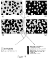
- Figure 8 shows alternative embodiments of the hydraulic agent used in the present invention.
- the hydraulic agent is silicone-based, has a high molecular weight, and a viscosity of at least 10,000 centipoise.
- a silicone fluid may be used, being linear or partially cross-linked, or alternatively a composite agent of cross linked solid silicone rubber particles and silicone fluid.
- a composite agent gives an improved viscoelastic response.
- An agent comprising solid silicone rubber particles suspended in a silicone fluid matrix ( Figures 8a and 8b) tends to emphasise the viscosity properties of the agent over the elastic properties.
- the particles may for example, be spherical, cylindrical, tube-shaped, ring-shaped or platelets.
- the smallest dimension of the solid particles is not less than 0.3 mm.
- an agent comprising a porous flexible silicone rubber solid filled with silicone liquid (Figures 8c and 8d) emphasises the elastic properties.
- the solid particles provide elastic resistance to deformation. Further, the shear forces in the agent increase with particle content, thus increasing the viscous resistance to flow.
- the composite material can be tailored for specific joint requirements.
Landscapes
- Health & Medical Sciences (AREA)
- Transplantation (AREA)
- Biomedical Technology (AREA)
- Cardiology (AREA)
- Oral & Maxillofacial Surgery (AREA)
- Engineering & Computer Science (AREA)
- Heart & Thoracic Surgery (AREA)
- Vascular Medicine (AREA)
- Life Sciences & Earth Sciences (AREA)
- Animal Behavior & Ethology (AREA)
- General Health & Medical Sciences (AREA)
- Public Health (AREA)
- Veterinary Medicine (AREA)
- Orthopedic Medicine & Surgery (AREA)
- Prostheses (AREA)
Applications Claiming Priority (2)
| Application Number | Priority Date | Filing Date | Title |
|---|---|---|---|
| GBGB9807386.9A GB9807386D0 (en) | 1998-04-07 | 1998-04-07 | Prosthetic device |
| GB9807386 | 1998-04-07 |
Publications (1)
| Publication Number | Publication Date |
|---|---|
| EP0948947A2 true EP0948947A2 (de) | 1999-10-13 |
Family
ID=10829956
Family Applications (1)
| Application Number | Title | Priority Date | Filing Date |
|---|---|---|---|
| EP99302709A Withdrawn EP0948947A2 (de) | 1998-04-07 | 1999-04-07 | Hydraulisches Prothesengelenk |
Country Status (2)
| Country | Link |
|---|---|
| EP (1) | EP0948947A2 (de) |
| GB (1) | GB9807386D0 (de) |
Cited By (9)
| Publication number | Priority date | Publication date | Assignee | Title |
|---|---|---|---|---|
| WO2008071975A1 (en) | 2006-12-14 | 2008-06-19 | Chas A. Blatchford & Sons Limited | A prosthetic ankle joint mechanism |
| EP1487378A4 (de) * | 2002-05-03 | 2009-10-28 | Freedom Innovations Llc | Fussprothese mit energieübertragungsmedium mit variabler viskoser flüssigkeit |
| US7686848B2 (en) | 2000-06-30 | 2010-03-30 | Freedom Innovations, Llc | Prosthetic foot with energy transfer |
| CN101785716A (zh) * | 2010-03-19 | 2010-07-28 | 上海理工大学 | 地形自适应仿生踝关节装置 |
| US7985265B2 (en) | 2006-12-14 | 2011-07-26 | Chas. A. Blatchford & Sons Limited | Prosthetic ankle and foot combination |
| WO2012104591A1 (en) | 2011-02-03 | 2012-08-09 | Blatchford Products Limited | A lower limb prosthesis |
| US8628585B2 (en) | 2007-12-14 | 2014-01-14 | Blatchford Products Limited | Lower limb prosthesis |
| US8641780B2 (en) | 2005-11-14 | 2014-02-04 | Blatchford Products Limited | Adjustment device for a lower limb prosthesis |
| EP3427701A1 (de) | 2007-02-22 | 2019-01-16 | Blatchford Products Limited | Kombination aus fussgelenk- und fussprothese |
Families Citing this family (1)
| Publication number | Priority date | Publication date | Assignee | Title |
|---|---|---|---|---|
| CN114869548B (zh) * | 2022-04-26 | 2024-05-31 | 吉林大学 | 仿生被动多自由度踝关节假肢 |
-
1998
- 1998-04-07 GB GBGB9807386.9A patent/GB9807386D0/en not_active Ceased
-
1999
- 1999-04-07 EP EP99302709A patent/EP0948947A2/de not_active Withdrawn
Cited By (20)
| Publication number | Priority date | Publication date | Assignee | Title |
|---|---|---|---|---|
| US7686848B2 (en) | 2000-06-30 | 2010-03-30 | Freedom Innovations, Llc | Prosthetic foot with energy transfer |
| EP1487378A4 (de) * | 2002-05-03 | 2009-10-28 | Freedom Innovations Llc | Fussprothese mit energieübertragungsmedium mit variabler viskoser flüssigkeit |
| US8641780B2 (en) | 2005-11-14 | 2014-02-04 | Blatchford Products Limited | Adjustment device for a lower limb prosthesis |
| US8740991B2 (en) | 2006-12-14 | 2014-06-03 | Blatchford Products Limited | Prosthetic ankle joint mechanism |
| US10130495B2 (en) | 2006-12-14 | 2018-11-20 | Blatchford Products Limited | Prosthetic ankle and foot combination |
| US7985265B2 (en) | 2006-12-14 | 2011-07-26 | Chas. A. Blatchford & Sons Limited | Prosthetic ankle and foot combination |
| US11679008B2 (en) | 2006-12-14 | 2023-06-20 | Blatchford Products Limited | Prosthetic ankle joint mechanism |
| US8574312B2 (en) | 2006-12-14 | 2013-11-05 | Blatchford Products Limited | Prosthetic ankle joint mechanism |
| US11529246B2 (en) | 2006-12-14 | 2022-12-20 | Blatchford Products Limited | Prosthetic ankle and foot combination |
| EP2124843A1 (de) | 2006-12-14 | 2009-12-02 | CHAS. A. BLATCHFORD & SONS LIMITED | Fussgelenksprothesen-mechanismus |
| WO2008071975A1 (en) | 2006-12-14 | 2008-06-19 | Chas A. Blatchford & Sons Limited | A prosthetic ankle joint mechanism |
| US9132023B2 (en) | 2006-12-14 | 2015-09-15 | Blatchford Products Limited | Prosthetic ankle and foot combination |
| US9433513B2 (en) | 2006-12-14 | 2016-09-06 | Blatchford Products Limited | Prosthetic ankle joint mechanism |
| US9999526B2 (en) | 2006-12-14 | 2018-06-19 | Blatchford Products Limited | Prosthetic ankle joint mechanism |
| EP3342376A1 (de) | 2006-12-14 | 2018-07-04 | Blatchford Products Limited | Prothetischer knöchelgelenkmechanismus |
| EP3427701A1 (de) | 2007-02-22 | 2019-01-16 | Blatchford Products Limited | Kombination aus fussgelenk- und fussprothese |
| EP3725272A1 (de) | 2007-02-22 | 2020-10-21 | Blatchford Products Limited | Kombination aus fussgelenk- und fussprothese |
| US8628585B2 (en) | 2007-12-14 | 2014-01-14 | Blatchford Products Limited | Lower limb prosthesis |
| CN101785716A (zh) * | 2010-03-19 | 2010-07-28 | 上海理工大学 | 地形自适应仿生踝关节装置 |
| WO2012104591A1 (en) | 2011-02-03 | 2012-08-09 | Blatchford Products Limited | A lower limb prosthesis |
Also Published As
| Publication number | Publication date |
|---|---|
| GB9807386D0 (en) | 1998-06-03 |
Similar Documents
| Publication | Publication Date | Title |
|---|---|---|
| US8317876B2 (en) | Artificial foot | |
| EP0948947A2 (de) | Hydraulisches Prothesengelenk | |
| US11529246B2 (en) | Prosthetic ankle and foot combination | |
| US6764521B2 (en) | Multi-axial ankle joint | |
| CA2213097C (en) | Adjustable prosthesis joint | |
| JP4019631B2 (ja) | 摩擦が低減した椎間板補綴具 | |
| CA2570459C (en) | Artificial foot | |
| US8057547B2 (en) | Articulating intervertebral disc prosthesis | |
| EP2124842B1 (de) | Prothetische sprunggelenk-fuss-baugruppe | |
| EP0720841A2 (de) | Knöchelgelenkprothese | |
| US20050055101A1 (en) | Endoprosthesis of the knee and/or other joints | |
| US20050261783A1 (en) | Multi-axial fitting with shock absorption for prosthetic foot | |
| EP2663264A1 (de) | Künstlicher knöchel, künstlicher fuss und künstliches bein | |
| CN222657270U (zh) | 仿生液压假脚 | |
| US7044984B2 (en) | High profile multiaxial prosthetic foot | |
| US9283088B2 (en) | Artificial intervertebral disc | |
| JP3436513B2 (ja) | 義 足 | |
| US20210106440A1 (en) | Passive prosthetic knee | |
| KR102743218B1 (ko) | 발목 각도를 조절할 수 있는 인공발 조립체 | |
| CN118647346A (zh) | 关节 | |
| RU2084208C1 (ru) | Протез бедра | |
| CN118415799A (zh) | 仿生液压踝关节阻尼缸 |
Legal Events
| Date | Code | Title | Description |
|---|---|---|---|
| PUAI | Public reference made under article 153(3) epc to a published international application that has entered the european phase |
Free format text: ORIGINAL CODE: 0009012 |
|
| AK | Designated contracting states |
Kind code of ref document: A2 Designated state(s): AT BE CH CY DE DK ES FI FR GB GR IE IT LI LU MC NL PT SE |
|
| AX | Request for extension of the european patent |
Free format text: AL;LT;LV;MK;RO;SI |
|
| STAA | Information on the status of an ep patent application or granted ep patent |
Free format text: STATUS: THE APPLICATION HAS BEEN WITHDRAWN |
|
| 18W | Application withdrawn |
Withdrawal date: 20000519 |