EP0948917B1 - Vorrichtung zur Höheneinstellung eines Objektes - Google Patents
Vorrichtung zur Höheneinstellung eines Objektes Download PDFInfo
- Publication number
- EP0948917B1 EP0948917B1 EP19990200893 EP99200893A EP0948917B1 EP 0948917 B1 EP0948917 B1 EP 0948917B1 EP 19990200893 EP19990200893 EP 19990200893 EP 99200893 A EP99200893 A EP 99200893A EP 0948917 B1 EP0948917 B1 EP 0948917B1
- Authority
- EP
- European Patent Office
- Prior art keywords
- crown
- crown wheel
- cylindrical
- acting
- coupling
- Prior art date
- Legal status (The legal status is an assumption and is not a legal conclusion. Google has not performed a legal analysis and makes no representation as to the accuracy of the status listed.)
- Expired - Lifetime
Links
- 230000008878 coupling Effects 0.000 claims description 45
- 238000010168 coupling process Methods 0.000 claims description 45
- 238000005859 coupling reaction Methods 0.000 claims description 45
- 230000005540 biological transmission Effects 0.000 claims description 21
- 239000000463 material Substances 0.000 claims description 9
- 238000001746 injection moulding Methods 0.000 claims description 4
- 230000002093 peripheral effect Effects 0.000 claims description 4
- 239000002184 metal Substances 0.000 claims description 3
- 238000010276 construction Methods 0.000 description 8
- 230000002028 premature Effects 0.000 description 2
- 150000001875 compounds Chemical class 0.000 description 1
- 239000003365 glass fiber Substances 0.000 description 1
- 238000012423 maintenance Methods 0.000 description 1
- 238000004519 manufacturing process Methods 0.000 description 1
Images


Classifications
-
- A—HUMAN NECESSITIES
- A47—FURNITURE; DOMESTIC ARTICLES OR APPLIANCES; COFFEE MILLS; SPICE MILLS; SUCTION CLEANERS IN GENERAL
- A47B—TABLES; DESKS; OFFICE FURNITURE; CABINETS; DRAWERS; GENERAL DETAILS OF FURNITURE
- A47B9/00—Tables with tops of variable height
- A47B9/04—Tables with tops of variable height with vertical spindle
Definitions
- the invention relates to a device for adjusting the height of an object, for instance a work surface, relative to a fixed point, cf. the preamble of claim 1.
- Such a device is known from the Netherlands patent application no. 9100324.
- the known device forms part of a column in a leg construction of adjustable length for supporting a work surface together with at least one other leg construction, which leg construction comprises: a foot for placing on the ground, a support for coupling to the work surface and two columns of adjustable length which are rigidly connected on one side to the foot and on the other side to the support.
- Each of the columns comprises two parts telescopically movable relative to each other, i.e. an upper part connected to the support and a lower part which is connected to the foot and provided with a spindle nut into which is screwed a screw spindle mounted on the upper part, and a right-angled transmission with conical toothed wheels present on the upper part.
- the right-angled transmissions of both columns have the same transmission ratios and are mutually coupled by means of a coupling shaft which has at least one cardan coupling and which is slidable to a limited extent relative to these right-angled transmissions such that when the screw spindles are rotated the columns undergo equal changes in length.
- the coupling shaft in the known leg construction has the at least one cardan coupling because in this leg construction driving or driven shafts extending in horizontal direction of the right-angled transmissions will never lie exactly mutually in line.
- the gear transmission comprises a first crown wheel and at least one cylindrical pinion co-acting therewith.
- a crown wheel is a toothed wheel for a right-angled transmission which co-acts with, and is therefore defined in its shape by, a cylindrical pinion with straight or angled evolvent teeth.
- the axial position of one of the two rotating, mutually perpendicular shafts coupled by the gear transmission is not at all critical when the pinion is sufficiently long: the shaft provided with the cylindrical pinion co-acting with the crown wheel can accommodate a clearance in axial direction which is determined by the difference in length of the teeth of the pinion and of the crown wheel.
- the coupling shaft is a rigid shaft which is provided with cylindrical first pinions co-acting with the respective first crown wheels.
- the first crown wheel in the respective devices is situated at the top of the respective screw spindles and the coupling shaft is assembled from two sub-shafts mutually coupled by a right-angled coupling gear transmission with a coupling crown wheel, which sub-shafts are each provided with a first cylindrical pinion co-acting with one of the respective first crown wheels and with a second cylindrical pinion co-acting with the coupling crown wheel.
- a compound coupling shaft coupled by a crown wheel and two respective co-acting cylindrical pinions provides the additional advantage relative to the known coupling shaft assembled from a cardan coupling, in addition to the above stated insensitivity to clearance in axial direction of the (component parts of the) coupling shaft, that the chosen angle between the component parts, should the position of the coupled adjusting devices require such, can be much smaller than in a coupling shaft with cardan coupling.
- Another advantage is that the coupled shafts can be driven by a drive on the shaft of the coupling crown wheel, whereby it is possible for instance to drive four adjusting devices placed in a rectangle simultaneously and in balance with only one drive motor placed on the diagonal of the rectangle.
- the first cylindrical pinions of the coupling shaft co-act at a location along the periphery of the respective first crown wheels with these crown wheels such that a rotation of the respective first crown wheels relative to each other will always be the same in any direction.
- this latter embodiment uses the option of coupling a crown wheel to a coupling shaft which intersects the produced part of the rotation axis of this crown wheel, wherein the pinion co-acts with the crown wheel at a location along the periphery diametrically opposite the only location possible when using a conical toothed wheel.
- one of the crown wheels can for instance be coupled to a horizontal, manually operable drive shaft.
- the rotation direction of this drive shaft can for instance be chosen solely by the choice of the location where it co-acts with the crown wheel such that a rotation to the right results in an upward movement of the object to be adjusted by this embodiment.
- the respective right-angled gear transmissions are provided by a modular element wherein the respective crown wheel and the at least one cylindrical pinion are mounted in each case in a housing, which housing substantially takes the form of for instance a straight prism in the base of which the crown wheel is mounted and in at least one of the standing side surfaces of which is mounted a cylindrical pinion co-acting with the crown wheel.
- a housing is for instance fixed with its upper surface against the underside of the object, for instance a table top.
- the base of the straight prism is preferably a regular polygon, for instance a square.
- the housing substantially takes the form of a straight cylinder, in the base of which cylinder the crown wheel is mounted and wherein the wall of this cylinder comprises at least one wall part which is rotatable in peripheral direction relative to the base and in which is mounted a cylindrical pinion co-acting with the crown wheel.
- This embodiment is for instance used in a height-adjustable combination of two table tops coupled at an angle in a horizontal plane, wherein the angle is adjustable.
- the respective crown wheels and cylindrical pinions in a device according to the invention can be manufactured from a plastic material and are advantageously manufactured from a sintered metal.
- the housing for a right-angled gear transmission is manufactured from injection moulding material.
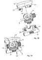
- Fig. 1 shows a device 1 for adjusting the height of a support plate 3 for screwing under a table top relative to a foot 2, a column 4 of adjustable length which comprises an upper hollow part 5 connected to support plate 3 and a lower hollow part 6 rigidly connected to foot 2, which parts 5, 6 are telescopically movable relative to one another.
- Rigidly connected to foot 2 is a spindle nut 7 into which a screw spindle 8 is screwed which is mounted on upper column part 5 and which is provided on its top with a crown wheel 29 which co-acts with a cylindrical pinion 28 of a horizontal drive shaft 11.
- Crown wheel 29 is mounted in a cylindrical housing, wherein a wall part 46 which is rotatable in peripheral direction and in which cylindrical pinion 28 is mounted extends from base 45. It is immediately apparent from the figure that the operation of right-angled transmission 29, 28 is inherently insensitive to clearance of drive shaft 11 in axial direction (as according to double arrow 16) at least as long as this clearance is an order of magnitude smaller than the length of the teeth of crown wheel 29, which will of course be the case in a practical situation.
- Fig. 2 shows a table top 22 which is supported by four length-adjustable, identical legs which are synchronously height-adjustable using horizontal drive shafts 11 which are coupled in the centre of table top 22 to a crown wheel 19 by second cylindrical pinions 20, which crown wheel 19 is driven by a motor 24 by means of a third cylindrical pinion 25 on a drive shaft 23.
- the position of drive motor 24 under table top 22 can be chosen such that motor 24 does not form an inconvenient obstacle for a user of the table.
- the crown wheel can be provided with a downward extending vertical drive shaft and drive motor 24 is for instance placed directly below crown wheel 19 and coupled to this drive shaft.
- Fig. 3A shows a housing 30 manufactured from injection moulding material which substantially takes the form of a regular (square) prism, in the base 31 of which a crown wheel 9 is mounted using a needle bearing (not shown) and in two 33, 34 of the standing side surfaces 32-34 of which is mounted a cylindrical pinion 10 co-acting with crown wheel 9.
- Crown wheel 9 and cylindrical pinions 10 are manufactured from sintered plastic material
- housing 30 is manufactured from injection moulding material PA6GV reinforced with ribs of glass-fibre material.
- Fig. 3B shows housing 30 of Fig. 3A in "exploded view” with the square base 31.
- Fig. 4A shows in top view a table top 15 with a combination of two adjusting devices, represented in the figure by the respective crown wheels 9, 9', which are coupled by a coupling shaft 11 and which co-act with cylindrical pinions 10, 10'.
- Coupling shaft 11 intersects the produced part of the rotation axis of right-hand crown wheel 9' so that pinions 10, 10' co-act at corresponding locations with respective crown wheels 9, 9', as a result of which a rotation of these crown wheels 9, 9' relative to each other will always be the same in any direction.
- the height of table 15 can be adjusted in simple manner using a drive handle 23, 23' placed on the left or right and provided with a pinion 25, 25' co-acting with respective crown wheels 9, 9'.
- Fig. 4B shows the table of fig. 4A in broken-away perspective.
- Fig. 5A shows in schematic top view a combination of a table top 41 of adjustable height which is provided with a round short side along which is coupled a second height-adjustable table top 42 provided with a corresponding concave side.
- the height of combination 41, 42 can be adjusted using three adjusting devices coupled by respective coupling shafts 11, 43 and represented in the figure by respective crown wheels 9, 29, 39 which co-act with respective cylindrical pinions 10, 28, 40.
- Coupling shafts 11, 43 intersect the produced part of the rotation axis of the respective crown wheels 9, 39 so that pinions 10, 40 co-act with respective crown wheels 9, 39 at corresponding locations, as a result of which a rotation of the three crown wheels 9, 29, 39 relative to each other will always be the same in any direction.
- the height of table 15 can be adjusted in simple manner using a drive handle 23 provided with a pinion 25 co-acting with crown wheel 39.
- Central crown wheel 29 is coupled to pinion 44 on coupling shaft 11 of attached table 42 in a manner such that the angle ⁇ between coupling shafts 11, 43, and therewith the angle between table tops 42, 41, is adjustable through a range of about 180°.
- Fig. 5B shows the table of fig. 5A in broken-away perspective.
- Fig. 6 shows a part of a straight cylindrical housing 50 for a height-adjusting device which can for instance be used under table top 41 of Fig. 5, with a base 45 in which a crown wheel 29 is mounted, wherein there extend from base 45 wall parts 46, 47 which are rotatable in peripheral direction and in which cylindrical pinions 28, 44 co-acting with crown wheel 29 are respectively mounted.
Landscapes
- Transmission Devices (AREA)
- Gear Transmission (AREA)
Claims (14)
- Vorrichtung (1) für das Einstellen der Höhe eines Objektes (3, 15, 22, 41, 42), zum Beispiel einer Arbeitsfläche, in Bezug auf einen Festpunkt (2) mittels einer um eine senkrechte Achse drehbaren Schraubenspindel (8), die an ihrer Spitze an das Objekt (3, 15, 22, 41, 42) mittels eines rechtwinkligen Zahnradgetriebes montiert ist und an ihrer gegenüberliegenden Seite in eine starr mit dem Festpunkt (2) gekoppelte Spindelmutter (7) geschraubt ist, und dieses Zahnradgetriebe Rotation der senkrechten Schraubenspindel (8) und Rotation eines Ritzels um eine waagerechte Achse (11, 43) verbindet, dadurch gekennzeichnet, dass das Zahnradgetriebe ein erstes Kronrad (29, 9, 39) und zumindest ein damit zusammenarbeitendes zylindrisches Ritzel (28, 10, 40) umfasst.
- Vorrichtung (1) nach Anspruch 1 und eine damit mittels einer Kupplungswelle gekoppelte zweite Vorrichtung (1) nach Anspruch 1, dadurch gekennzeichnet, dass die Kupplungswelle eine starre Welle (11, 43) ist, die mit zylindrischen ersten Ritzeln (28, 10, 40), welche mit den jeweiligen ersten Kronrädern (29, 9, 39) zusammenarbeiten, ausgestattet ist.
- Vorrichtung (1) nach Anspruch 1 und eine damit mittels einer Kupplungswelle gekoppelte zweite Vorrichtung (1) nach Anspruch 1, dadurch gekennzeichnet, dass sich das erste Kronrad (9) in den jeweiligen Vorrichtungen (1) an der Spitze der jeweiligen Schraubenspindeln (8) befindet und die Kupplungswelle aus zwei Teilwellen (11), die durch ein rechtwinkliges Kupplungszahnradgetriebe (19, 20) mit einem Kupplungskronrad (19) gegenseitig gekoppelt sind, zusammengesetzt ist, und jede dieser Teilwellen (11) mit einem ersten zylindrischen Ritzel (10), welches mit einem der jeweiligen ersten Kronräder (9) zusammenarbeitet, und mit einem zweiten zylindrischen Ritzel (20), welches mit dem Kupplungskronrad (19) zusammenarbeitet, versehen ist.
- Vorrichtung nach Anspruch 2 oder 3, dadurch gekennzeichnet, dass die ersten zylindrischen Ritzel der Kupplungswelle an einer Stelle längs des Umfangs der jeweiligen ersten Kronräder mit diesen Kronrädern so zusammenarbeiten, dass eine Drehung der jeweiligen ersten Kronräder in Bezug auf einander immer dieselbe Richtung hat.
- Vorrichtung nach einem der Ansprüche 1-4, dadurch gekennzeichnet, dass die jeweiligen rechtwinkligen Zahnradgetriebe durch ein modulares Element verschafft werden, wobei das jeweilige Kronrad (9, 29) und das zumindest eine zylindrische Ritzel (10, 28, 44) immer in einem Gehäuse (50) montiert sind.
- Vorrichtung nach Anspruch 5, dadurch gekennzeichnet, dass das Gehäuse im Wesentlichen die Form eines geraden Prismas (30) hat, in dessen Grundfläche das Kronrad montiert ist und in zumindest einer von dessen aufrechten Seitenflächen ein mit dem Kronrad zusammenarbeitendes zylindrisches Ritzel montiert ist.
- Vorrichtung nach Anspruch 6, dadurch gekennzeichnet, dass die Grundfläche des geraden Prismas ein regelmäßiges Vieleck ist.
- Vorrichtung nach Anspruch 7, dadurch gekennzeichnet, dass die Grundfläche des geraden Prismas ein Quadrat (31) ist.
- Vorrichtung nach Anspruch 5, dadurch gekennzeichnet, dass das Gehäuse im Wesentlichen die Form eines geraden Zylinders (50) hat, in der Grundfläche (45) dieses Zylinders (50) das Kronrad (29) montiert ist und wobei die Wand dieses Zylinders (50) wenigsten ein in Bezug auf die Grundfläche (45) in Umfangsrichtung drehbares Wandteil (46, 47) umfasst, in dem ein mit dem Kronrad (29) zusammenarbeitendes zylindrisches Ritzel (28, 44) montiert ist.
- Vorrichtung nach einem der Ansprüche 1-9, dadurch gekennzeichnet, dass die jeweiligen Kronräder aus einem Kunststoffmaterial hergestellt sind.
- Vorrichtung nach einem der Ansprüche 1-9, dadurch gekennzeichnet, dass die jeweiligen Kronräder aus einem Sintermetall hergestellt sind.
- Vorrichtung nach einem der Ansprüche 1-9, dadurch gekennzeichnet, dass die jeweiligen zylindrischen Ritzel aus einem Kunststoffmaterial hergestellt sind.
- Vorrichtung nach einem der Ansprüche 1-9, dadurch gekennzeichnet, dass die jeweiligen zylindrischen Ritzel aus einem Sintermetall hergestellt sind.
- Vorrichtung nach einem der Ansprüche 5-9, dadurch gekennzeichnet, dass das Gehäuse aus einem Spritzgussmaterial hergestellt ist.
Applications Claiming Priority (2)
| Application Number | Priority Date | Filing Date | Title |
|---|---|---|---|
| NL1008761 | 1998-03-31 | ||
| NL1008761A NL1008761C2 (nl) | 1998-03-31 | 1998-03-31 | Inrichting voor het instellen van de hoogte van een object. |
Publications (2)
| Publication Number | Publication Date |
|---|---|
| EP0948917A1 EP0948917A1 (de) | 1999-10-13 |
| EP0948917B1 true EP0948917B1 (de) | 2002-12-11 |
Family
ID=19766863
Family Applications (1)
| Application Number | Title | Priority Date | Filing Date |
|---|---|---|---|
| EP19990200893 Expired - Lifetime EP0948917B1 (de) | 1998-03-31 | 1999-03-23 | Vorrichtung zur Höheneinstellung eines Objektes |
Country Status (3)
| Country | Link |
|---|---|
| EP (1) | EP0948917B1 (de) |
| DE (1) | DE69904385T2 (de) |
| NL (1) | NL1008761C2 (de) |
Families Citing this family (1)
| Publication number | Priority date | Publication date | Assignee | Title |
|---|---|---|---|---|
| US6540191B2 (en) * | 2001-03-19 | 2003-04-01 | Lin-Ho Liu | Foot stand structure of an adjustable computer desk |
Family Cites Families (4)
| Publication number | Priority date | Publication date | Assignee | Title |
|---|---|---|---|---|
| IT1230005B (it) * | 1989-04-21 | 1991-09-20 | Giovannetti F | Dispositivo di sollevamento abbassamento, particolarmente per regolazione di livello. |
| NL9100324A (nl) | 1991-02-22 | 1992-09-16 | Engeland Management Bv Van | Pootconstructie. |
| NL9401735A (nl) * | 1994-10-19 | 1996-06-03 | Crown Gear Bv | Tandwieloverbrenging van een cilindrisch rondsel met een kroonwiel, het kroonwiel dat toegepast wordt in deze tandwieloverbrenging, een werkwijze volgens welke het kroonwiel gemaakt kan worden alsmede een gereedschap waarmee het kroonwiel gemaakt kan worden. |
| US5685510A (en) * | 1995-03-08 | 1997-11-11 | Prima Furniture (Aust) Pty Ltd | Height adjustment system for a desk or workstation |
-
1998
- 1998-03-31 NL NL1008761A patent/NL1008761C2/nl not_active IP Right Cessation
-
1999
- 1999-03-23 EP EP19990200893 patent/EP0948917B1/de not_active Expired - Lifetime
- 1999-03-23 DE DE1999604385 patent/DE69904385T2/de not_active Expired - Fee Related
Also Published As
| Publication number | Publication date |
|---|---|
| DE69904385D1 (de) | 2003-01-23 |
| NL1008761C2 (nl) | 1999-10-01 |
| DE69904385T2 (de) | 2003-09-04 |
| EP0948917A1 (de) | 1999-10-13 |
Similar Documents
| Publication | Publication Date | Title |
|---|---|---|
| US6148741A (en) | Table with adjustable table top portions | |
| US5292095A (en) | Levelling device, particularly for furniture | |
| US5685510A (en) | Height adjustment system for a desk or workstation | |
| CA1072168A (en) | Drafting table | |
| US6327985B1 (en) | Desk with expansible legs | |
| US6948892B2 (en) | Lift mechanism for plunge routers | |
| US20050016806A1 (en) | Lifting column preferably for height adjustable tables and method for manufacturnig thereof | |
| CA2143569A1 (en) | Height-adjustable work table | |
| US5560303A (en) | Dismantleable standing table | |
| US7487690B2 (en) | Elevating mechanism for furniture | |
| US20070284325A1 (en) | Height-adjustable supports for false floors | |
| EP0948917B1 (de) | Vorrichtung zur Höheneinstellung eines Objektes | |
| CA1284942C (en) | Height adjustment apparatus | |
| EP0685185A2 (de) | Tisch mit beweglicher Platte | |
| CA2220128A1 (en) | Adjustable steering column | |
| EP0379262B1 (de) | Höhenverstellbarer Tisch | |
| DE69205302T2 (de) | Tischbeinanordnung. | |
| US20030173479A1 (en) | Adjustable pedestal for boat accessory | |
| EP0426031B1 (de) | Industrienähmaschine und Tragtisch sowie Steuerungspedal dafür | |
| JPH0522114Y2 (de) | ||
| US7607397B2 (en) | Device for a wiggle-free table | |
| EP0931479A2 (de) | Verstellbares Bürosystem | |
| KR0114043Y1 (ko) | 높낮이 조절식 고정대가 구비된 캐스터 | |
| JPH0347544Y2 (de) | ||
| CN219669269U (zh) | 一种高度可调的牛眼台面 |
Legal Events
| Date | Code | Title | Description |
|---|---|---|---|
| PUAI | Public reference made under article 153(3) epc to a published international application that has entered the european phase |
Free format text: ORIGINAL CODE: 0009012 |
|
| AK | Designated contracting states |
Kind code of ref document: A1 Designated state(s): BE DE FR GB NL SE |
|
| AX | Request for extension of the european patent |
Free format text: AL;LT;LV;MK;RO;SI |
|
| 17P | Request for examination filed |
Effective date: 20000413 |
|
| AKX | Designation fees paid |
Free format text: BE DE FR GB NL SE |
|
| GRAG | Despatch of communication of intention to grant |
Free format text: ORIGINAL CODE: EPIDOS AGRA |
|
| 17Q | First examination report despatched |
Effective date: 20020515 |
|
| GRAG | Despatch of communication of intention to grant |
Free format text: ORIGINAL CODE: EPIDOS AGRA |
|
| GRAH | Despatch of communication of intention to grant a patent |
Free format text: ORIGINAL CODE: EPIDOS IGRA |
|
| GRAH | Despatch of communication of intention to grant a patent |
Free format text: ORIGINAL CODE: EPIDOS IGRA |
|
| GRAA | (expected) grant |
Free format text: ORIGINAL CODE: 0009210 |
|
| AK | Designated contracting states |
Kind code of ref document: B1 Designated state(s): BE DE FR GB NL SE |
|
| PG25 | Lapsed in a contracting state [announced via postgrant information from national office to epo] |
Ref country code: FR Free format text: LAPSE BECAUSE OF NON-PAYMENT OF DUE FEES Effective date: 20021211 |
|
| REG | Reference to a national code |
Ref country code: GB Ref legal event code: FG4D |
|
| REF | Corresponds to: |
Ref document number: 69904385 Country of ref document: DE Date of ref document: 20030123 |
|
| PG25 | Lapsed in a contracting state [announced via postgrant information from national office to epo] |
Ref country code: SE Free format text: LAPSE BECAUSE OF FAILURE TO SUBMIT A TRANSLATION OF THE DESCRIPTION OR TO PAY THE FEE WITHIN THE PRESCRIBED TIME-LIMIT Effective date: 20030311 |
|
| PLBE | No opposition filed within time limit |
Free format text: ORIGINAL CODE: 0009261 |
|
| STAA | Information on the status of an ep patent application or granted ep patent |
Free format text: STATUS: NO OPPOSITION FILED WITHIN TIME LIMIT |
|
| EN | Fr: translation not filed | ||
| 26N | No opposition filed |
Effective date: 20030912 |
|
| PGFP | Annual fee paid to national office [announced via postgrant information from national office to epo] |
Ref country code: GB Payment date: 20040219 Year of fee payment: 6 |
|
| PGFP | Annual fee paid to national office [announced via postgrant information from national office to epo] |
Ref country code: BE Payment date: 20050208 Year of fee payment: 7 |
|
| PG25 | Lapsed in a contracting state [announced via postgrant information from national office to epo] |
Ref country code: GB Free format text: LAPSE BECAUSE OF NON-PAYMENT OF DUE FEES Effective date: 20050323 |
|
| PGFP | Annual fee paid to national office [announced via postgrant information from national office to epo] |
Ref country code: DE Payment date: 20050331 Year of fee payment: 7 |
|
| GBPC | Gb: european patent ceased through non-payment of renewal fee |
Effective date: 20050323 |
|
| PGFP | Annual fee paid to national office [announced via postgrant information from national office to epo] |
Ref country code: NL Payment date: 20060215 Year of fee payment: 8 |
|
| PG25 | Lapsed in a contracting state [announced via postgrant information from national office to epo] |
Ref country code: BE Free format text: LAPSE BECAUSE OF NON-PAYMENT OF DUE FEES Effective date: 20060331 |
|
| PG25 | Lapsed in a contracting state [announced via postgrant information from national office to epo] |
Ref country code: DE Free format text: LAPSE BECAUSE OF NON-PAYMENT OF DUE FEES Effective date: 20061003 |
|
| NLV4 | Nl: lapsed or anulled due to non-payment of the annual fee |
Effective date: 20071001 |
|
| BERE | Be: lapsed |
Owner name: *VAN ENGELAND MANAGEMENT B.V. Effective date: 20060331 |
|
| PG25 | Lapsed in a contracting state [announced via postgrant information from national office to epo] |
Ref country code: NL Free format text: LAPSE BECAUSE OF NON-PAYMENT OF DUE FEES Effective date: 20071001 |