EP0948696B1 - A window having a window frame - Google Patents
A window having a window frame Download PDFInfo
- Publication number
- EP0948696B1 EP0948696B1 EP97913112A EP97913112A EP0948696B1 EP 0948696 B1 EP0948696 B1 EP 0948696B1 EP 97913112 A EP97913112 A EP 97913112A EP 97913112 A EP97913112 A EP 97913112A EP 0948696 B1 EP0948696 B1 EP 0948696B1
- Authority
- EP
- European Patent Office
- Prior art keywords
- frame structure
- profiles
- side members
- window according
- window
- Prior art date
- Legal status (The legal status is an assumption and is not a legal conclusion. Google has not performed a legal analysis and makes no representation as to the accuracy of the status listed.)
- Expired - Lifetime
Links
- 239000002023 wood Substances 0.000 claims abstract description 27
- 239000002184 metal Substances 0.000 claims abstract description 15
- 230000005540 biological transmission Effects 0.000 claims description 5
- 230000000717 retained effect Effects 0.000 claims description 4
- 239000000853 adhesive Substances 0.000 claims description 3
- 230000001070 adhesive effect Effects 0.000 claims description 3
- 239000011810 insulating material Substances 0.000 claims description 3
- 238000004519 manufacturing process Methods 0.000 description 5
- 239000000463 material Substances 0.000 description 5
- 238000009413 insulation Methods 0.000 description 4
- 241000238631 Hexapoda Species 0.000 description 2
- 230000005494 condensation Effects 0.000 description 2
- 238000009833 condensation Methods 0.000 description 2
- 238000010276 construction Methods 0.000 description 2
- 238000007789 sealing Methods 0.000 description 2
- 238000009423 ventilation Methods 0.000 description 2
- 230000015572 biosynthetic process Effects 0.000 description 1
- 230000000694 effects Effects 0.000 description 1
- 230000007613 environmental effect Effects 0.000 description 1
- 238000010438 heat treatment Methods 0.000 description 1
- 238000000034 method Methods 0.000 description 1
- 239000013464 silicone adhesive Substances 0.000 description 1
Images


Classifications
-
- E—FIXED CONSTRUCTIONS
- E04—BUILDING
- E04D—ROOF COVERINGS; SKY-LIGHTS; GUTTERS; ROOF-WORKING TOOLS
- E04D13/00—Special arrangements or devices in connection with roof coverings; Protection against birds; Roof drainage ; Sky-lights
- E04D13/03—Sky-lights; Domes; Ventilating sky-lights
- E04D13/0305—Supports or connecting means for sky-lights of flat or domed shape
- E04D13/031—Supports or connecting means for sky-lights of flat or domed shape characterised by a frame for connection to an inclined roof
Definitions
- the present invention relates to a window, in particular for mounting in an inclined roof surface, comprising a frame structure with top, bottom and side members and a relative to the frame structure openable, top-hung sash structure with an insulating pane enchased between top, bottom and side members of metal or plastic profiles and manufactured with dimensions corresponding to the exterior dimensions of the frame structure for direct abutment on a gasket fastened to the exterior edge surfaces of the top, bottom and side members of the frame structure.
- Windows of this type and of many different designs are among others known from DK Patent No. 74,858.
- big demands are made on among others the tightness and the insulating property of the window.
- manufacture of the window is to be rationally made without too many cost-increasing factors and with a cost-minded choice of material.
- the object of the invention is to provide a window which is both easy and cheap to manufacture, but which still meets the demand made in respect to insulating property, tightness, etc.
- a window which is characterized in that the top, bottom and side members of the frame structure comprise wood profiles which have substantially parallelogram-shaped cross-sections, said exterior edge surfaces being positioned in a common plane, with which the adjacent opposite side faces of the profile cross-section form an angle of 95 to 140°.
- the parallelogram-shaped cross-section gives a higher stability in the corners of the frame structure than a rectangular cross-section of the same area.
- the parallelogram-shaped design of the wood profiles of the frame structure gives in combination with the big pane area an improved total light incidence compared with a window, in which the side surfaces of the frame structure extend perpendicularly to the sash plane.
- the advantage is obtained that exchange of accessories like roller blinds and insect nets is facilitated, as the access to the window is made easier on account of the oblique interior sides of the frame structure.
- the wood profiles may be connected in profiled mitre joints, which in addition to making the mounting of the frame structure of the window simple provides an additional improvement of the insulation, the end faces of the wood profiles, which are badly insulating, being covered.
- a preferred embodiment is characterized in that the thickness of the wood profiles is comparatively small and that for improving the heat insulating properties additional insulating elements of a good heat-insulating material are retained to the side of the profile cross-section which is intended to form the interior side for the top, bottom and side members of the frame structure.
- top, bottom and side members of the frame structure are on the interior side facing the light admitting area of the window covered by metal sheet profiles for providing a good heat transmission to border areas of the insulating pane.
- This heat transmission brings about a heating of the edge of the pane itself, whereby the formation of condensation is considerably reduced relative to windows having a traditional "cold" pane edge.
- the additional insulating elements preferably extend over a part of the width of the wood profiles and are supported by abutment lists of wood connected with the wood profiles.
- the above-mentioned reuse has been further improved in an embodiment, in which the top, bottom and side members of the frame structure with said additional insulating elements and possible heat-transmitting metal sheet profiles as a whole is connected solely by means of non-adhesive connection members in the mitre joints.
- the window may be assembled by and large completely without separate connection members and will consequently be easily dismountable with a view to reusing the various components of the window.
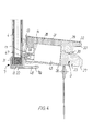
- a top-hung roof or skylight window comprises a frame structure having a top member 1, side members 2 and a bottom member 3 and a top-hung sash structure openable relative thereto, in which an insulating pane 4 is enchased between a top member 5, side members 6 and a bottom member 7.
- the insulating pane 4 is manufactured with dimensions which substantially correspond to the exterior measures of the frame structure, such that the edge surfaces 8-10 of the pane 4 are substantially flush with the exterior sides of the top, side and bottom members 1-3 of the frame structure, and such that the insulating pane 4 in the closed position of the window directly abuts resilient sealing profiles 11-13, which are retained in grooves 14-16 in exterior edge surfaces 17-19 of the top, side and bottom members 1-3 of the frame structure.
- the sash profiles 5-7 are in the embodiment shown designed as metal sheet profiles with substantially L-shaped cross-section with a small wall thickness and mutually connected by corner joints 20, which, as shown in Fig. 1, may be made as 45° angular joints.
- the insulating pane 4 is secured by an adhesive sealing, for instance, as shown, by joints 21 and 22 of silicone adhesive.
- the wall 5a-7a of the L-shaped cross-section of the sash profiles 5-7, which abuts the edge surfaces 8-10 of the insulating pane 4, is, as shown, manufactured with such a width that in the closed position it overlaps the exterior side of the frame member 1-3 lying behind it and is at its interior edge folded for providing a softly rounded edge.
- the top, side and bottom members 1-3 of the frame are made from wood profiles 23, which, as shown in Fig. 6, are connected at the corners in profiled mitre joints 24, for instance with undulating abutment surfaces 25.
- This method of joining has the advantage that it partly provides a safe mutual locking of the top, side and bottom members 1-3, partly gives optimum insulation properties, the end surfaces of the wood profiles being removed from the exterior sides of the frame members.
- the frame wood profiles 23 are manufactured with a substantially parallelogram-shaped cross-section, in which the above-mentioned exterior edge surfaces 17-19 lie in a common plane, with which the adjacent opposite side surfaces 26, 27 of the profile cross-section form an angle v of for instance 95 to 140°, in the embodiment shown 96°.
- this profile cross-section which provides the structure with the shape of a low frustum of a pyramid, an advantageous possibility is obtained of manufacturing the frame structure with oblique interior sides, which is desirable with a view to mounting various forms of accessories like for instance roller blinds and insect nets, and with a minimum consumption of material, the profiles 23 being, as shown, manufactured with a comparatively small thickness.
- the thermal insulation property of the frame structures is improved by the fact that to the side of the profiles 23, which is intended for forming the interior side of the frame structure, additional, substantially rod-shaped insulating elements 28 are retained, which may be manufactured from a suitable, well insulating material.
- the insulating elements 28 extend across a part of the width of the wood profiles 23 and are supported by abutment lists 29 connected with the wood profiles 23 by groove and tongue joints 30.
- the top, side and bottom members 1-3 of the frame structures end in a covering of metal sheet profiles 31, which covers the entire interior side and extends towards the edge area of the insulating pane 4.
- metal sheet profiles 31 which covers the entire interior side and extends towards the edge area of the insulating pane 4.
- abutment lists 29, as shown are designed such that they at a distance from the wood profiles 23 form a nose portion 32, may be exploited for retaining the covering profile 31 by manufacturing it with a folded edge portion 33.
- This design of the frame structure entails that the wood profiles 23 and the abutment lists 29 connected therewith may be releasably connected with the insulating elements 28 and the covering profiles 31, which can easily be exchanged for lacquering/change of colour or for mounting of fittings for accessories, and which entails a simple, and from an environmental point of view advantageous construction, which makes it possible at a subsequent dismounting to easily separate the frame structure into wood profiles, insulating elements and metal profiles with a view to reusing the materials to a high degree.
- top, side and bottom members 1-3 of the frame structure are in a manner known per se covered by flashing profiles 34-36 of metal sheets.
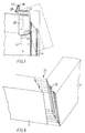
- grooves 35a For fastening of the window to the underlying roof structure grooves 35a have, as shown in Fig. 3, been provided in the frame side members 2 for receiving fixing angles or straps, which are subsequently secured to the roof structure.
- the sash and frame constructions shown makes it in an advantageous manner possible to make the top hinge of the window integral with the top members 1 and 5 of the frame and sash structures, respectively.
- a fitting member 37 with a hinge pin forming member in the form of a projecting wall portion 38 may be connected with the flashing profile 34 for the frame top member 1, whereas a substantially V-shaped hook member 39 is made integral with the wall portion 5a of the L-shaped metal sheet profile for the sash top member 5, said hook member 39 being hinged on the upward wall portion 38 and having an opening angle in the range of 20 to 30°.
- securing means To hold the hook member 39 and the projecting wall portion 38 in mutual engagement and to make a turning of the sash structure to a ventilation position possible, securing means have, as shown in Fig. 5, been secured to adjacent pairs of side members 2 and 6 of the frame and sash structures, said securing means comprising, in the embodiment shown, holding means 40 and 41, for instance in the form of blocks of a wear-resistant plastic material, with part-cylindrical guide surfaces 42 and 43 with axis in the pivot axis of the hinge 44.
- the holding means 40 and 41 will keep the hinge members 38 and 39 in mutual engagement, whereas they, when the sash structure is turned beyond this opening angle range to the position shown by a dotted line in Fig. 5, will be disengaged and thus allow an easy dismounting of the sash structure relative to the frame structure.
- a window operator may in a manner known per se be mounted in connection with the bottom members 3 and 7 of the frame and sash structures, for instance an electrically driven chain operator with an operator housing 45 accommodated in a recess in the wood profile 23 and the insulating element 28 and an operating chain 46, which may be detachably connected with a sash fitting 47 secured to a for instance L-shaped console 48 in connection with the L-shaped sash profile 7a, for instance secured to its folded edge portion.
Landscapes
- Engineering & Computer Science (AREA)
- Architecture (AREA)
- Civil Engineering (AREA)
- Structural Engineering (AREA)
- Wing Frames And Configurations (AREA)
- Securing Of Glass Panes Or The Like (AREA)
- Window Of Vehicle (AREA)
- Special Wing (AREA)
- Specific Sealing Or Ventilating Devices For Doors And Windows (AREA)
- Door And Window Frames Mounted To Openings (AREA)
- Dry Shavers And Clippers (AREA)
Abstract
Description
Claims (10)
- A window, in particular for mounting in an inclined roof surface, comprising a frame structure with top, bottom and side members (1-3) and a relative to the frame structure openable, top-hung sash structure with an insulating pane (4) enchased between top, bottom and side members (5-7) of metal or plastic profiles and manufactured with dimensions corresponding to the exterior dimensions of the frame structure for direct abutment on a gasket (11-13) fastened to the exterior edge surfaces (17-19) of the top, bottom and side members of the frame structure, characterized in that the top, bottom and side members of the frame structure comprise wood profiles (23) with substantially parallelogram-shaped cross-sections, said exterior edge surfaces (17-19) being positioned in a common plane, with which the adjacent opposite side faces (26,27) of the profile cross-section form an angle (v) of 95 to 140°.
- A window according to claim 1, characterized in that said wood profiles (23) are connected in profiled mitre joints (25).
- A window according to claim 2, characterized in that the thickness of the wood profiles (23) is comparatively small and that for improving the heat insulating properties additional insulating elements (28) of a good heat-insulating material are retained to the side of the profile cross-section which is intended to form the interior side for the top, bottom and side members (1-3) of the frame structure.
- A window according to claim 1, 2 or 3, characterized in that the top, bottom and side members (1-3) of the frame structure on the interior side facing the light admitting area of the window are covered by metal sheet profiles (31) for providing a good heat transmission to border areas of the insulating pane (4).
- A window according to claim 3, characterized in that the additional insulating elements (28) extend over a part of the width of the wood profiles (23) and are supported by abutment lists (29) of wood connected with the wood profiles.
- A window according to claims 4 and 5, characterized in that said abutment lists (29) at the inwards facing edge side of the wood profiles (23) form a nose portion (32) for retaining a folded edge member (33) of the heat-transmitting metal sheet profiles (31), said nose portion being situated at a distance from the adjacent inner side of the wood profiles.
- A window according to one of the claims 3-6, characterized in that the top, bottom and side members (1-3) with said additional insulating elements (28) and possible heat-transmitting metal sheet profiles (31) as a whole is connected solely by means of non-adhesive connection members in the mitre joints (24).
- A window according to one of the claims 2-7, characterized in that the outwards facing side faces of the top, bottom and side members (1-3) of the frame structure are covered by flashing profiles (34-36) of metal sheet.
- A window according to claim 8, characterized in that a fitting member (37) is connected with the flashing profile (34) for the top member (1) of the frame structure, said fitting member having a projecting wall portion (38), which by engagement with a substantially V-shaped hook member (39) integral with the top member (5) of the sash structure forms a pivoting hinge for the sash structure relative to the frame structure.
- A window according to claim 9, characterized in that holding means (40,41) are fastened to at least one adjacent pair of the side members (2,6) of the frame and sash structures, which holding means, within a predetermined opening angle range for the sash structure and calculated from the closed position, hold the V-shaped hook member (39) and said projecting wall portion (38) in mutual engagement, but which, when turning the sash structure beyond said opening angle range, allow removal of the sash structure from the frame structure.
Applications Claiming Priority (3)
| Application Number | Priority Date | Filing Date | Title |
|---|---|---|---|
| DK199601315A DK131596A (en) | 1996-11-19 | 1996-11-19 | Window with frame |
| DK131596 | 1996-11-19 | ||
| PCT/DK1997/000515 WO1998022686A1 (en) | 1996-11-19 | 1997-11-13 | A window having a window frame |
Publications (2)
| Publication Number | Publication Date |
|---|---|
| EP0948696A1 EP0948696A1 (en) | 1999-10-13 |
| EP0948696B1 true EP0948696B1 (en) | 2001-05-30 |
Family
ID=8103477
Family Applications (1)
| Application Number | Title | Priority Date | Filing Date |
|---|---|---|---|
| EP97913112A Expired - Lifetime EP0948696B1 (en) | 1996-11-19 | 1997-11-13 | A window having a window frame |
Country Status (13)
| Country | Link |
|---|---|
| US (1) | US6295774B1 (en) |
| EP (1) | EP0948696B1 (en) |
| JP (1) | JP4073495B2 (en) |
| AT (1) | ATE201740T1 (en) |
| AU (1) | AU5047798A (en) |
| CA (1) | CA2270563A1 (en) |
| DE (1) | DE69705064T2 (en) |
| DK (2) | DK131596A (en) |
| EA (1) | EA199900478A1 (en) |
| ES (1) | ES2158529T3 (en) |
| HU (1) | HU221557B (en) |
| PL (1) | PL185390B1 (en) |
| WO (1) | WO1998022686A1 (en) |
Cited By (2)
| Publication number | Priority date | Publication date | Assignee | Title |
|---|---|---|---|---|
| WO2009064258A3 (en) * | 2007-11-14 | 2010-05-27 | Grenzone Pte Ltd | Photovoltaic skylight and method of manufacture therefor |
| CN106437416A (en) * | 2016-09-27 | 2017-02-22 | 福建省南平铝业股份有限公司 | Window frame connecting material, energy saving window, and method for rapidly modifying old window into energy saving window |
Families Citing this family (14)
| Publication number | Priority date | Publication date | Assignee | Title |
|---|---|---|---|---|
| DE10060668B4 (en) * | 2000-12-06 | 2007-05-03 | Reinhard Fuhrmann | roofcurb |
| US6804918B2 (en) | 2001-01-19 | 2004-10-19 | Vkr Holding A/S | Roof window assembly comprising a window component and an external screening accessory |
| DE10295851T1 (en) * | 2001-01-19 | 2003-12-24 | Vkr Holding As S Diameter Borg | Skylight assembly and individual parts |
| US20050262782A1 (en) * | 2004-06-01 | 2005-12-01 | Marvin Lumber And Cedar Company D/B/A Marvin Windows And Doors | Self flashing assembly |
| US8006445B2 (en) * | 2006-06-29 | 2011-08-30 | Pella Corporation | Self-sealing window installation and method |
| GB201110481D0 (en) * | 2011-06-21 | 2011-08-03 | Keylite Roof Windows Ltd | An insulated roof window |
| GB2492380B (en) * | 2011-06-30 | 2017-01-25 | The Metal Window Co Ltd | Window thermal shield |
| PL3252249T3 (en) * | 2016-05-30 | 2022-01-10 | Vkr Holding A/S | A roof window refurbishment system and method for refurbishing a roof window |
| WO2020147909A1 (en) * | 2019-01-14 | 2020-07-23 | Vkr Holding A/S | Pivot roof window with sash comprising vacuum insulated glass unit overlapping bottom frame profile |
| EP4466422B1 (en) * | 2022-03-31 | 2025-04-16 | VKR Holding A/S | A kit with a covering assembly and a method for mounting a roof window |
| PL4466416T3 (en) * | 2022-03-31 | 2025-09-08 | Vkr Holding A/S | ROOF WINDOW WITH A FRAME WITH RECEIVING STRUCTURES |
| PL4466418T3 (en) * | 2022-03-31 | 2025-05-05 | Vkr Holding A/S | A roof window comprising releasable components |
| USD1065597S1 (en) | 2023-03-30 | 2025-03-04 | Vkr Holding A/S | Window component |
| USD1052757S1 (en) | 2023-03-30 | 2024-11-26 | Vkr Holding A/S | Window |
Family Cites Families (9)
| Publication number | Priority date | Publication date | Assignee | Title |
|---|---|---|---|---|
| DE149991C (en) * | ||||
| US1045580A (en) * | 1910-05-18 | 1912-11-26 | Benjamin S Mcclellan | Metallic sash. |
| DK74858C (en) * | 1948-11-20 | 1952-10-20 | Willum Benedikt Kann Rasmussen | Roof window. |
| CH430138A (en) * | 1965-11-01 | 1967-02-15 | Schweizer Metallbau Ernst | Device for attaching metal profile rails to window and door frames made of wood |
| SE406787B (en) * | 1977-06-01 | 1979-02-26 | Zanda Ab | HANGING, SLOPING CEILINGS |
| US4250673A (en) * | 1979-05-25 | 1981-02-17 | Kawneer Company, Inc. | Window replacement system |
| SE438705B (en) * | 1980-08-14 | 1985-04-29 | Lars Lagergren | SIGN PROFILES FOR THE FRAME PIECE |
| DE3048961C2 (en) * | 1980-12-24 | 1985-08-14 | Fa. Franz Bisping, 4400 Münster | Window or the like |
| US4776141A (en) * | 1987-03-02 | 1988-10-11 | Powell J William | Skylights |
-
1996
- 1996-11-19 DK DK199601315A patent/DK131596A/en not_active Application Discontinuation
-
1997
- 1997-11-13 DE DE69705064T patent/DE69705064T2/en not_active Expired - Lifetime
- 1997-11-13 US US09/297,044 patent/US6295774B1/en not_active Expired - Fee Related
- 1997-11-13 DK DK97913112T patent/DK0948696T3/en active
- 1997-11-13 ES ES97913112T patent/ES2158529T3/en not_active Expired - Lifetime
- 1997-11-13 EP EP97913112A patent/EP0948696B1/en not_active Expired - Lifetime
- 1997-11-13 CA CA002270563A patent/CA2270563A1/en not_active Abandoned
- 1997-11-13 AU AU50477/98A patent/AU5047798A/en not_active Abandoned
- 1997-11-13 EA EA199900478A patent/EA199900478A1/en not_active IP Right Cessation
- 1997-11-13 JP JP52308498A patent/JP4073495B2/en not_active Expired - Fee Related
- 1997-11-13 AT AT97913112T patent/ATE201740T1/en not_active IP Right Cessation
- 1997-11-13 WO PCT/DK1997/000515 patent/WO1998022686A1/en not_active Ceased
- 1997-11-13 HU HU0000077A patent/HU221557B/en not_active IP Right Cessation
- 1997-11-13 PL PL97333658A patent/PL185390B1/en not_active IP Right Cessation
Cited By (2)
| Publication number | Priority date | Publication date | Assignee | Title |
|---|---|---|---|---|
| WO2009064258A3 (en) * | 2007-11-14 | 2010-05-27 | Grenzone Pte Ltd | Photovoltaic skylight and method of manufacture therefor |
| CN106437416A (en) * | 2016-09-27 | 2017-02-22 | 福建省南平铝业股份有限公司 | Window frame connecting material, energy saving window, and method for rapidly modifying old window into energy saving window |
Also Published As
| Publication number | Publication date |
|---|---|
| EA000672B1 (en) | 2000-02-28 |
| EP0948696A1 (en) | 1999-10-13 |
| HU221557B (en) | 2002-11-28 |
| US6295774B1 (en) | 2001-10-02 |
| WO1998022686A1 (en) | 1998-05-28 |
| DK131596A (en) | 1998-05-20 |
| DK0948696T3 (en) | 2001-09-24 |
| DE69705064T2 (en) | 2002-03-21 |
| PL185390B1 (en) | 2003-04-30 |
| EA199900478A1 (en) | 2000-02-28 |
| ES2158529T3 (en) | 2001-09-01 |
| DE69705064D1 (en) | 2001-07-05 |
| HUP0000077A3 (en) | 2000-12-28 |
| JP2001504182A (en) | 2001-03-27 |
| AU5047798A (en) | 1998-06-10 |
| CA2270563A1 (en) | 1998-05-28 |
| JP4073495B2 (en) | 2008-04-09 |
| ATE201740T1 (en) | 2001-06-15 |
| HUP0000077A2 (en) | 2000-07-28 |
Similar Documents
| Publication | Publication Date | Title |
|---|---|---|
| US6295774B1 (en) | Window having a window frame | |
| EP0948692B1 (en) | A window having an improved window frame structure | |
| US6640508B2 (en) | Roof window assembly and components | |
| EP0948693B1 (en) | A window having an improved sash structure | |
| EP0951609B1 (en) | A window, in particular for mounting in an inclined roof surface | |
| US6202373B1 (en) | Top-hung window | |
| EP0948694B1 (en) | A window with a reduced risk of condensation | |
| US20080034677A1 (en) | Rooflight | |
| EP2578764B1 (en) | A roof window with a barrel bolt | |
| EP0481911B1 (en) | A frame structure mainly for inward opening windows or glass doors | |
| JPH0738539Y2 (en) | Roof eaves seal structure | |
| CZ9901773A3 (en) | Window | |
| CZ9901775A3 (en) | Window | |
| JP2553369Y2 (en) | Skylight unit | |
| EP0872620A2 (en) | Improved metal door |
Legal Events
| Date | Code | Title | Description |
|---|---|---|---|
| PUAI | Public reference made under article 153(3) epc to a published international application that has entered the european phase |
Free format text: ORIGINAL CODE: 0009012 |
|
| 17P | Request for examination filed |
Effective date: 19990421 |
|
| AK | Designated contracting states |
Kind code of ref document: A1 Designated state(s): AT BE CH DE DK ES FI FR GB GR IE IT LI LU MC NL PT SE |
|
| AX | Request for extension of the european patent |
Free format text: AL PAYMENT 19990421;LT PAYMENT 19990421;LV PAYMENT 19990421;MK PAYMENT 19990421;RO PAYMENT 19990421;SI PAYMENT 19990421 |
|
| GRAG | Despatch of communication of intention to grant |
Free format text: ORIGINAL CODE: EPIDOS AGRA |
|
| 17Q | First examination report despatched |
Effective date: 20000711 |
|
| GRAG | Despatch of communication of intention to grant |
Free format text: ORIGINAL CODE: EPIDOS AGRA |
|
| GRAH | Despatch of communication of intention to grant a patent |
Free format text: ORIGINAL CODE: EPIDOS IGRA |
|
| GRAH | Despatch of communication of intention to grant a patent |
Free format text: ORIGINAL CODE: EPIDOS IGRA |
|
| GRAA | (expected) grant |
Free format text: ORIGINAL CODE: 0009210 |
|
| RAP1 | Party data changed (applicant data changed or rights of an application transferred) |
Owner name: VKR HOLDING A/S |
|
| AK | Designated contracting states |
Kind code of ref document: B1 Designated state(s): AT BE CH DE DK ES FI FR GB GR IE IT LI LU MC NL PT SE |
|
| AX | Request for extension of the european patent |
Free format text: AL PAYMENT 19990421;LT PAYMENT 19990421;LV PAYMENT 19990421;MK PAYMENT 19990421;RO PAYMENT 19990421;SI PAYMENT 19990421 |
|
| LTIE | Lt: invalidation of european patent or patent extension | ||
| PG25 | Lapsed in a contracting state [announced via postgrant information from national office to epo] |
Ref country code: FI Free format text: LAPSE BECAUSE OF FAILURE TO SUBMIT A TRANSLATION OF THE DESCRIPTION OR TO PAY THE FEE WITHIN THE PRESCRIBED TIME-LIMIT Effective date: 20010530 |
|
| REF | Corresponds to: |
Ref document number: 201740 Country of ref document: AT Date of ref document: 20010615 Kind code of ref document: T |
|
| REG | Reference to a national code |
Ref country code: CH Ref legal event code: EP |
|
| REF | Corresponds to: |
Ref document number: 69705064 Country of ref document: DE Date of ref document: 20010705 |
|
| REG | Reference to a national code |
Ref country code: IE Ref legal event code: FG4D |
|
| ITF | It: translation for a ep patent filed | ||
| PG25 | Lapsed in a contracting state [announced via postgrant information from national office to epo] |
Ref country code: SE Free format text: LAPSE BECAUSE OF FAILURE TO SUBMIT A TRANSLATION OF THE DESCRIPTION OR TO PAY THE FEE WITHIN THE PRESCRIBED TIME-LIMIT Effective date: 20010830 Ref country code: PT Free format text: LAPSE BECAUSE OF FAILURE TO SUBMIT A TRANSLATION OF THE DESCRIPTION OR TO PAY THE FEE WITHIN THE PRESCRIBED TIME-LIMIT Effective date: 20010830 |
|
| PG25 | Lapsed in a contracting state [announced via postgrant information from national office to epo] |
Ref country code: GR Free format text: LAPSE BECAUSE OF FAILURE TO SUBMIT A TRANSLATION OF THE DESCRIPTION OR TO PAY THE FEE WITHIN THE PRESCRIBED TIME-LIMIT Effective date: 20010831 |
|
| REG | Reference to a national code |
Ref country code: CH Ref legal event code: NV Representative=s name: TROESCH SCHEIDEGGER WERNER AG |
|
| REG | Reference to a national code |
Ref country code: ES Ref legal event code: FG2A Ref document number: 2158529 Country of ref document: ES Kind code of ref document: T3 |
|
| REG | Reference to a national code |
Ref country code: DK Ref legal event code: T3 |
|
| ET | Fr: translation filed | ||
| PG25 | Lapsed in a contracting state [announced via postgrant information from national office to epo] |
Ref country code: MC Free format text: LAPSE BECAUSE OF NON-PAYMENT OF DUE FEES Effective date: 20011113 Ref country code: LU Free format text: LAPSE BECAUSE OF NON-PAYMENT OF DUE FEES Effective date: 20011113 Ref country code: IE Free format text: LAPSE BECAUSE OF FAILURE TO SUBMIT A TRANSLATION OF THE DESCRIPTION OR TO PAY THE FEE WITHIN THE PRESCRIBED TIME-LIMIT Effective date: 20011113 Ref country code: DK Free format text: LAPSE BECAUSE OF NON-PAYMENT OF DUE FEES Effective date: 20011113 |
|
| REG | Reference to a national code |
Ref country code: GB Ref legal event code: IF02 |
|
| PLBE | No opposition filed within time limit |
Free format text: ORIGINAL CODE: 0009261 |
|
| STAA | Information on the status of an ep patent application or granted ep patent |
Free format text: STATUS: NO OPPOSITION FILED WITHIN TIME LIMIT |
|
| 26N | No opposition filed | ||
| REG | Reference to a national code |
Ref country code: DK Ref legal event code: EBP |
|
| REG | Reference to a national code |
Ref country code: IE Ref legal event code: MM4A |
|
| PGFP | Annual fee paid to national office [announced via postgrant information from national office to epo] |
Ref country code: NL Payment date: 20031110 Year of fee payment: 7 |
|
| PGFP | Annual fee paid to national office [announced via postgrant information from national office to epo] |
Ref country code: GB Payment date: 20031112 Year of fee payment: 7 Ref country code: AT Payment date: 20031112 Year of fee payment: 7 |
|
| PGFP | Annual fee paid to national office [announced via postgrant information from national office to epo] |
Ref country code: BE Payment date: 20031113 Year of fee payment: 7 |
|
| PGFP | Annual fee paid to national office [announced via postgrant information from national office to epo] |
Ref country code: ES Payment date: 20031118 Year of fee payment: 7 |
|
| PGFP | Annual fee paid to national office [announced via postgrant information from national office to epo] |
Ref country code: CH Payment date: 20031119 Year of fee payment: 7 |
|
| PG25 | Lapsed in a contracting state [announced via postgrant information from national office to epo] |
Ref country code: GB Free format text: LAPSE BECAUSE OF NON-PAYMENT OF DUE FEES Effective date: 20041113 Ref country code: AT Free format text: LAPSE BECAUSE OF NON-PAYMENT OF DUE FEES Effective date: 20041113 |
|
| PG25 | Lapsed in a contracting state [announced via postgrant information from national office to epo] |
Ref country code: ES Free format text: LAPSE BECAUSE OF NON-PAYMENT OF DUE FEES Effective date: 20041115 |
|
| PG25 | Lapsed in a contracting state [announced via postgrant information from national office to epo] |
Ref country code: LI Free format text: LAPSE BECAUSE OF NON-PAYMENT OF DUE FEES Effective date: 20041130 Ref country code: CH Free format text: LAPSE BECAUSE OF NON-PAYMENT OF DUE FEES Effective date: 20041130 Ref country code: BE Free format text: LAPSE BECAUSE OF NON-PAYMENT OF DUE FEES Effective date: 20041130 |
|
| BERE | Be: lapsed |
Owner name: *VKR HOLDING A/S Effective date: 20041130 |
|
| PG25 | Lapsed in a contracting state [announced via postgrant information from national office to epo] |
Ref country code: NL Free format text: LAPSE BECAUSE OF NON-PAYMENT OF DUE FEES Effective date: 20050601 |
|
| GBPC | Gb: european patent ceased through non-payment of renewal fee |
Effective date: 20041113 |
|
| REG | Reference to a national code |
Ref country code: CH Ref legal event code: PL |
|
| NLV4 | Nl: lapsed or anulled due to non-payment of the annual fee |
Effective date: 20050601 |
|
| REG | Reference to a national code |
Ref country code: ES Ref legal event code: FD2A Effective date: 20041115 |
|
| BERE | Be: lapsed |
Owner name: *VKR HOLDING A/S Effective date: 20041130 |
|
| PGFP | Annual fee paid to national office [announced via postgrant information from national office to epo] |
Ref country code: IT Payment date: 20081125 Year of fee payment: 12 |
|
| PGFP | Annual fee paid to national office [announced via postgrant information from national office to epo] |
Ref country code: FR Payment date: 20081113 Year of fee payment: 12 |
|
| REG | Reference to a national code |
Ref country code: FR Ref legal event code: ST Effective date: 20100730 |
|
| PG25 | Lapsed in a contracting state [announced via postgrant information from national office to epo] |
Ref country code: FR Free format text: LAPSE BECAUSE OF NON-PAYMENT OF DUE FEES Effective date: 20091130 |
|
| PGFP | Annual fee paid to national office [announced via postgrant information from national office to epo] |
Ref country code: DE Payment date: 20101119 Year of fee payment: 14 |
|
| PG25 | Lapsed in a contracting state [announced via postgrant information from national office to epo] |
Ref country code: IT Free format text: LAPSE BECAUSE OF NON-PAYMENT OF DUE FEES Effective date: 20091113 |
|
| REG | Reference to a national code |
Ref country code: DE Ref legal event code: R119 Ref document number: 69705064 Country of ref document: DE Effective date: 20120601 |
|
| PG25 | Lapsed in a contracting state [announced via postgrant information from national office to epo] |
Ref country code: DE Free format text: LAPSE BECAUSE OF NON-PAYMENT OF DUE FEES Effective date: 20120601 |