EP0948693B1 - A window having an improved sash structure - Google Patents
A window having an improved sash structure Download PDFInfo
- Publication number
- EP0948693B1 EP0948693B1 EP97913114A EP97913114A EP0948693B1 EP 0948693 B1 EP0948693 B1 EP 0948693B1 EP 97913114 A EP97913114 A EP 97913114A EP 97913114 A EP97913114 A EP 97913114A EP 0948693 B1 EP0948693 B1 EP 0948693B1
- Authority
- EP
- European Patent Office
- Prior art keywords
- sash
- profiles
- insulating pane
- window
- frame structure
- Prior art date
- Legal status (The legal status is an assumption and is not a legal conclusion. Google has not performed a legal analysis and makes no representation as to the accuracy of the status listed.)
- Expired - Lifetime
Links
Images


Classifications
-
- E—FIXED CONSTRUCTIONS
- E04—BUILDING
- E04D—ROOF COVERINGS; SKY-LIGHTS; GUTTERS; ROOF-WORKING TOOLS
- E04D13/00—Special arrangements or devices in connection with roof coverings; Protection against birds; Roof drainage ; Sky-lights
- E04D13/03—Sky-lights; Domes; Ventilating sky-lights
- E04D13/0305—Supports or connecting means for sky-lights of flat or domed shape
- E04D13/031—Supports or connecting means for sky-lights of flat or domed shape characterised by a frame for connection to an inclined roof
Definitions
- the present invention relates to a window, in particular for mounting in an inclined roof surface, comprising a frame structure with top, bottom and side members and a relative to the frame structure openable, top-hung sash structure with an insulating pane enchased between top, bottom and side members of metal or plastic profiles, the sash profiles being metal sheet profiles with substantially L-shaped cross-section and small wall thickness, and a resilient gasket profile being secured to the outwards facing edge surfaces of the top, bottom and side members of the frame structure as abutment for the interior side of the insulating pane.
- Windows of this type are i.a. known from DK patent No. 74858 and US patent No. 4,776,141. In such windows it is a general problem to obtain sufficient tightness relative to the room inside, in particular if for reasons of appearance, when the windows are for instance to be used in protected buildings, traditional building materials cannot be used.
- the object of the invention is to improve a window of the type mentioned by way of introduction, which is both easy and inexpensive to manufacture, but which at the same time meets the demands made on a window, which is to be used in occupied areas.
- a window which is characterized in that the insulating pane is manufactured with such dimensions that its edges, when the window is closed, are placed substantially in flush with the exterior sides of the frame structure, that the sash profiles comprise a comparatively narrow wall portion in abutment on an edge portion of the exterior side of the insulating pane and a second wall portion connected therewith through a rectangular corner and abutting an edge surface of the insulating pane, said second wall portion overlapping, in the closed position of the window, the exterior side of the frame member lying behind, and in that the insulating pane is secured in said wall portions of the sash profiles solely by adhesive sealing.
- the sash profiles are preferably mutually connected by welding, and the adhesive sealing of the insulating pane is preferably made by a silicone adhesive, which results in a simple and inexpensive manufacture.
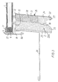
- a top-hung roof or skylight window comprises a frame structure having a top member 1, side members 2 and a bottom member 3 and a top-hung sash structure openable relative thereto, in which an insulating pane 4 is enchased between a top member 5, side members 6 and a bottom member 7.
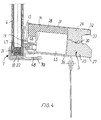
- the insulating pane 4 is manufactured with dimensions which substantially correspond to the exterior measures of the frame structure, such that the edge surfaces 8-10 of the pane 4 are substantially flush with the exterior sides of the top, side and bottom members 1-3 of the frame structure, and such that the insulating pane 4 in the closed position of the window directly abuts resilient sealing profiles 11-13, which are retained in grooves 14-16 in exterior edge surfaces 17-19 of the top, side and bottom members 1-3 of the frame structure.
- the sash profiles 5-7 are in the embodiment shown designed as metal sheet profiles with substantially L-shaped cross-section with a small wall thickness and mutually connected by corner joints 20, which, as shown in Fig. 1, may be made as 45° angular joints.
- the insulating pane 4 is secured by an adhesive sealing, for instance, as shown, by joints 21 and 22 of silicone adhesive.
- the wall 5a-7a of the L-shaped cross-section of the sash profiles 5-7, which abuts the edge surfaces 8-10 of the insulating pane 4, is, as shown, manufactured with such a width that in the closed position it overlaps the exterior side of the frame member 1-3 lying behind it and is at its interior edge folded for providing a softly rounded edge.
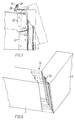
- the top, side and bottom members 1-3 of the frame are made from wood profiles 23, which, as shown in Fig. 6, are connected at the corners in profiled mitre joints 24, for instance with undulating abutment surfaces 25.
- This method of joining has the advantage that it partly provides a safe mutual locking of the top, side and bottom members 1-3, partly gives optimum insulation properties, the end surfaces of the wood profiles being removed from the exterior sides of the frame members.
- the frame wood profiles 23 are manufactured with a substantially parallelogram-shaped cross-section, in which the above-mentioned exterior edge surfaces 17-19 lie in a common plane, with which the adjacent opposite side surfaces 26, 27 of the profile cross-section form an angle v of for instance 95 to 140°, in the embodiment shown 96°.
- this profile cross-section which provides the structure with the shape of a low frustum of a pyramid, an advantageous possibility is obtained of manufacturing the frame structure with oblique interior sides, which is desirable with a view to mounting various forms of accessories like for instance roller blinds and insect nets, and with a minimum consumption of material, the profiles 23 being, as shown, manufactured with a comparatively small thickness.
- the thermal insulation property of the frame structures is improved by the fact that to the side of the profiles 23, which is intended for forming the interior side of the frame structure, additional, substantially rod-shaped insulating elements 28 are retained, which may be manufactured from a suitable, well insulating material.
- the insulating elements 28 extend across a part of the width of the wood profiles 23 and are supported by abutment lists 29 connected with the wood profiles 23 by groove and tongue joints 30.
- the top, side and bottom members 1-3 of the frame structures end in a covering of metal sheet profiles 31, which covers the entire interior side and extends towards the edge area of the insulating pane 4.
- metal sheet profiles 31 which covers the entire interior side and extends towards the edge area of the insulating pane 4.
- abutment lists 29, as shown are designed such that they at a distance from the wood profiles 23 form a nose portion 32, may be exploited for retaining the covering profile 31 by manufacturing it with a folded edge portion 33.
- This design of the frame structure entails that the wood profiles 23 and the abutment lists 29 connected therewith may be releasably connected with the insulating elements 28 and the covering profiles 31, which can easily be exchanged for lacquering/change of colour or for mounting of fittings for accessories, and which entails a simple, and from an environmental point of view advantageous construction, which makes it possible at a subsequent dismounting to easily separate the frame structure into wood profiles, insulating elements and metal profiles with a view to reusing the materials to a high degree.
- top, side and bottom members 1-3 of the frame structure are in a manner known per se covered by flashing profiles 34-36 of metal sheets.
- grooves 35a For fastening of the window to the underlying roof structure grooves 35a have, as shown in Fig. 3, been provided in the frame side members 2 for receiving fixing angles or straps, which are subsequently secured to the roof structure.
- the sash and frame constructions shown makes it in an advantageous manner possible to make the top hinge of the window integral with the top members 1 and 5 of the frame and sash structures, respectively.
- a fitting member 37 with a hinge pin forming member in the form of a projecting wall portion 38 may be connected with the flashing profile 34 for the frame top member 1, whereas a substantially V-shaped hook member 39 is made integral with the wall portion 5a of the L-shaped metal sheet profile for the sash top member 5, said hook member 39 being hinged on the upward wall portion 38 and having an opening angle in the range of 20 to 30°.
- securing means To hold the hook member 39 and the projecting wall portion 38 in mutual engagement and to make a turning of the sash structure to a ventilation position possible, securing means have, as shown in Fig. 5, been secured to adjacent pairs of side members 2 and 6 of the frame and sash structures, said securing means comprising, in the embodiment shown, holding means 40 and 41, for instance in the form of blocks of a wear-resistant plastic material, with part-cylindrical guide surfaces 42 and 43 with axis in the pivot axis of the hinge 44.
- the holding means 40 and 41 will keep the hinge members 38 and 39 in mutual engagement, whereas they, when the sash structure is turned beyond this opening angle range to the position shown by a dotted line in Fig. 5, will be disengaged and thus allow an easy dismounting of the sash structure relative to the frame structure.
- a window operator may in a manner known per se be mounted in connection with the bottom members 3 and 7 of the frame and sash structures, for instance an electrically driven chain operator with an operator housing 45 accommodated in a recess in the wood profile 23 and the insulating element 28 and an operating chain 46, which may be detachably connected with a sash fitting 47 secured to a for instance L-shaped console 48 in connection with the L-shaped sash profile 7a, for instance secured to its folded edge portion.
Landscapes
- Engineering & Computer Science (AREA)
- Architecture (AREA)
- Civil Engineering (AREA)
- Structural Engineering (AREA)
- Wing Frames And Configurations (AREA)
- Building Environments (AREA)
- Door And Window Frames Mounted To Openings (AREA)
- Special Wing (AREA)
- Belt Conveyors (AREA)
- Lining Or Joining Of Plastics Or The Like (AREA)
Abstract
Description
Claims (5)
- A window, in particular for mounting in an inclined roof surface, comprising a frame structure with top, bottom and side members (1-3) and a relative to the frame structure openable, top-hung sash structure with an insulating pane (4) enchased between top, bottom and side members (5-7) of metal or plastic profiles, the sash profiles being metal sheet profiles with substantially L-shaped cross-section and small wall thickness, and a resilient gasket profile (11-13) being secured to the outwards facing edge surfaces (17-19) of the top, bottom and side members of the frame structure as abutment for the interior side of the insulating pane, characterized in that the insulating pane (4) is manufactured with such dimensions that its edges, when the window is closed, are placed substantially in flush with the exterior sides of the frame structure, that the sash profiles (5-7) comprise a comparatively narrow wall portion in abutment on an edge portion of the exterior side of the insulating pane and a second wall portion (5a-7a) connected therewith through a rectangular corner and abutting an edge surface of the insulating pane, said second wall portion overlapping, in the closed position of the window, the exterior side of the frame member (1-3) lying behind, and in that the insulating pane (4) is secured in said wall portions of the sash profiles (5-7) solely by adhesive sealing (21,22).
- A window according to claim 1, characterized in that the sash profiles (5-7) are mutually connected by welding.
- A window according to claim 1 or 2, characterized in that the wall (5a) of the profile cross-section for the top member (5) of the sash structure abutting an edge surface of the insulating pane is integral with a substantially V-shaped hook member (39) which, together with a substantially L-shaped fitting member (37), which is connected with the frame top member (1) and has a projecting wall portion (38) engaging the V-shaped hook member, forms a pivoting hinge for the sash structure relative to the frame structure.
- A window according to claim 3, characterized in that holding means (40,41) are fastened to at least one adjacent pair of the side members (2,6) of the frame and sash structures, which holding means, within a predetermined opening angle range for the sash structure and calculated from the closed position, hold the V-shaped hook member (39) and said projecting wall portion (38) in mutual engagement, but which, when turning the sash structure beyond said opening angle range, allow removal of the sash structure from the frame structure.
- A window according to any of the preceding claims, characterizedin that the adhesive sealing (21,22) of the insulating pane (4) is a silicone adhesive.
Priority Applications (1)
| Application Number | Priority Date | Filing Date | Title |
|---|---|---|---|
| SI9730348T SI0948693T1 (en) | 1996-11-19 | 1997-11-13 | A window having an improved sash structure |
Applications Claiming Priority (3)
| Application Number | Priority Date | Filing Date | Title |
|---|---|---|---|
| DK199601318A DK131896A (en) | 1996-11-19 | 1996-11-19 | Window with improved belt construction |
| DK131896 | 1996-11-19 | ||
| PCT/DK1997/000517 WO1998022682A1 (en) | 1996-11-19 | 1997-11-13 | A window having an improved sash structure |
Publications (2)
| Publication Number | Publication Date |
|---|---|
| EP0948693A1 EP0948693A1 (en) | 1999-10-13 |
| EP0948693B1 true EP0948693B1 (en) | 2002-04-03 |
Family
ID=8103511
Family Applications (1)
| Application Number | Title | Priority Date | Filing Date |
|---|---|---|---|
| EP97913114A Expired - Lifetime EP0948693B1 (en) | 1996-11-19 | 1997-11-13 | A window having an improved sash structure |
Country Status (9)
| Country | Link |
|---|---|
| US (1) | US6286267B1 (en) |
| EP (1) | EP0948693B1 (en) |
| JP (1) | JP2001504184A (en) |
| AT (1) | ATE215658T1 (en) |
| AU (1) | AU5047998A (en) |
| DE (1) | DE69711694T2 (en) |
| DK (2) | DK131896A (en) |
| ES (1) | ES2175376T3 (en) |
| WO (1) | WO1998022682A1 (en) |
Families Citing this family (13)
| Publication number | Priority date | Publication date | Assignee | Title |
|---|---|---|---|---|
| DE10295851T1 (en) | 2001-01-19 | 2003-12-24 | Vkr Holding As S Diameter Borg | Skylight assembly and individual parts |
| US6804918B2 (en) | 2001-01-19 | 2004-10-19 | Vkr Holding A/S | Roof window assembly comprising a window component and an external screening accessory |
| PL207278B1 (en) * | 2002-03-20 | 2010-11-30 | Vkr Holding As | Method of providing a joint between a plate member and a frame profile, and a frame structure comprising such a joint |
| US20050000173A1 (en) * | 2003-07-02 | 2005-01-06 | Vkr Holding A/S | Skylight with sealing gasket |
| WO2005049951A1 (en) * | 2003-11-21 | 2005-06-02 | Vkr Holding A/S | Drainage system in a roofwindow and roofwindow |
| NZ552504A (en) * | 2007-01-09 | 2008-02-29 | Flashman Flashing Systems Ltd | Improved jamb flashing with acute angle at the free edge |
| EP2204524B1 (en) * | 2008-12-30 | 2017-10-18 | VKR Holding A/S | A window or door assembly comprising a frame structure with a groove for receiving a lining structure |
| IT1398016B1 (en) * | 2010-02-05 | 2013-02-04 | Veronesi | PACKED FOR OPENING IN A WALL OR IN A ROOF. |
| GB201110481D0 (en) * | 2011-06-21 | 2011-08-03 | Keylite Roof Windows Ltd | An insulated roof window |
| JP5995601B2 (en) * | 2012-08-08 | 2016-09-21 | 三協立山株式会社 | Window unit |
| DE102017208514B4 (en) * | 2017-05-19 | 2025-05-15 | Roto Frank Ag | Inner lining for a roof window arrangement having a roof window and corresponding roof window arrangement |
| PL4466418T3 (en) * | 2022-03-31 | 2025-05-05 | Vkr Holding A/S | A roof window comprising releasable components |
| DK182067B1 (en) * | 2023-12-18 | 2025-06-27 | Vkr Holding As | A roof window with a sealing system |
Family Cites Families (12)
| Publication number | Priority date | Publication date | Assignee | Title |
|---|---|---|---|---|
| FR1588003A (en) * | 1968-10-18 | 1970-04-03 | ||
| SE409564B (en) * | 1976-04-05 | 1979-08-27 | Bofors Ab | IN A WALL OPENING MOUNTABLE FORNSTER OR DOOR FRAME |
| US4594821A (en) * | 1980-07-25 | 1986-06-17 | Bechtold Paul E | Skylight assembly |
| DK157144C (en) * | 1986-07-03 | 1990-04-16 | Rasmussen Kann Ind As | WINDOW ELEMENT |
| DE3705777A1 (en) * | 1987-02-24 | 1988-09-01 | Lothar Goeritz | Process for renovating windows and glass doors, and windows or glass doors produced by this process |
| US4986039A (en) * | 1988-11-23 | 1991-01-22 | Sne Enterprises, Inc. | Operating-vent glass-glazed standing-seam skylight |
| US5103603A (en) * | 1990-05-18 | 1992-04-14 | Thermo-Vu Sunlite Industries, Inc. | Continuously hinged skylight assembly |
| US5207036A (en) * | 1990-06-28 | 1993-05-04 | Wasco Products, Inc. | Skylight construction |
| US5148643A (en) * | 1990-06-28 | 1992-09-22 | Wasco Products, Inc. | Skylight construction |
| US5199234A (en) * | 1991-01-08 | 1993-04-06 | Andersen Corporation | Skylight assembly |
| DK94193D0 (en) * | 1993-08-17 | 1993-08-17 | Deko Loft & Vaeg As | DOORKARM OR SUBJECT TO SUCH ONE, NECESSARY FOR USE WITH LIGHT WALLS |
| US5669186A (en) * | 1995-09-29 | 1997-09-23 | Thermo-Vu Sunlite Industries, Inc. | Openable hatch apparatus for a skylight |
-
1996
- 1996-11-19 DK DK199601318A patent/DK131896A/en not_active Application Discontinuation
-
1997
- 1997-11-13 DK DK97913114T patent/DK0948693T3/en active
- 1997-11-13 JP JP52308698A patent/JP2001504184A/en not_active Ceased
- 1997-11-13 AU AU50479/98A patent/AU5047998A/en not_active Abandoned
- 1997-11-13 WO PCT/DK1997/000517 patent/WO1998022682A1/en not_active Ceased
- 1997-11-13 US US09/297,048 patent/US6286267B1/en not_active Expired - Fee Related
- 1997-11-13 ES ES97913114T patent/ES2175376T3/en not_active Expired - Lifetime
- 1997-11-13 DE DE69711694T patent/DE69711694T2/en not_active Expired - Lifetime
- 1997-11-13 EP EP97913114A patent/EP0948693B1/en not_active Expired - Lifetime
- 1997-11-13 AT AT97913114T patent/ATE215658T1/en not_active IP Right Cessation
Also Published As
| Publication number | Publication date |
|---|---|
| ES2175376T3 (en) | 2002-11-16 |
| EP0948693A1 (en) | 1999-10-13 |
| DK131896A (en) | 1998-05-20 |
| US6286267B1 (en) | 2001-09-11 |
| DE69711694D1 (en) | 2002-05-08 |
| WO1998022682A1 (en) | 1998-05-28 |
| DK0948693T3 (en) | 2002-07-08 |
| JP2001504184A (en) | 2001-03-27 |
| ATE215658T1 (en) | 2002-04-15 |
| AU5047998A (en) | 1998-06-10 |
| DE69711694T2 (en) | 2002-11-14 |
Similar Documents
| Publication | Publication Date | Title |
|---|---|---|
| US6164025A (en) | Window having an improved window frame structure | |
| US6640508B2 (en) | Roof window assembly and components | |
| EP0948696B1 (en) | A window having a window frame | |
| US6286267B1 (en) | Window having an improved sash structure | |
| EP2318609B1 (en) | Deck-mounted skylight having unitary cladding component | |
| US5682713A (en) | Rotatable bracket securing a window frame to a roof | |
| EP0951609B1 (en) | A window, in particular for mounting in an inclined roof surface | |
| EP0948695B1 (en) | A top-hung window | |
| US20080034677A1 (en) | Rooflight | |
| CA2849364C (en) | A roof window with a covering means for a frame | |
| EP0481911B1 (en) | A frame structure mainly for inward opening windows or glass doors | |
| CZ9901773A3 (en) | Window | |
| EP0872620A2 (en) | Improved metal door | |
| AU2023216872A1 (en) | Closure framing system | |
| CZ9901775A3 (en) | Window |
Legal Events
| Date | Code | Title | Description |
|---|---|---|---|
| PUAI | Public reference made under article 153(3) epc to a published international application that has entered the european phase |
Free format text: ORIGINAL CODE: 0009012 |
|
| 17P | Request for examination filed |
Effective date: 19990421 |
|
| AK | Designated contracting states |
Kind code of ref document: A1 Designated state(s): AT BE CH DE DK ES FI FR GB GR IE IT LI LU MC NL PT SE |
|
| AX | Request for extension of the european patent |
Free format text: AL PAYMENT 19990421;LT PAYMENT 19990421;LV PAYMENT 19990421;MK PAYMENT 19990421;RO PAYMENT 19990421;SI PAYMENT 19990421 |
|
| RAP1 | Party data changed (applicant data changed or rights of an application transferred) |
Owner name: VKR HOLDING A/S |
|
| GRAG | Despatch of communication of intention to grant |
Free format text: ORIGINAL CODE: EPIDOS AGRA |
|
| 17Q | First examination report despatched |
Effective date: 20010802 |
|
| GRAG | Despatch of communication of intention to grant |
Free format text: ORIGINAL CODE: EPIDOS AGRA |
|
| GRAG | Despatch of communication of intention to grant |
Free format text: ORIGINAL CODE: EPIDOS AGRA |
|
| GRAH | Despatch of communication of intention to grant a patent |
Free format text: ORIGINAL CODE: EPIDOS IGRA |
|
| REG | Reference to a national code |
Ref country code: GB Ref legal event code: IF02 |
|
| GRAH | Despatch of communication of intention to grant a patent |
Free format text: ORIGINAL CODE: EPIDOS IGRA |
|
| GRAA | (expected) grant |
Free format text: ORIGINAL CODE: 0009210 |
|
| AK | Designated contracting states |
Kind code of ref document: B1 Designated state(s): AT BE CH DE DK ES FI FR GB GR IE IT LI LU MC NL PT SE |
|
| AX | Request for extension of the european patent |
Free format text: AL PAYMENT 19990421;LT PAYMENT 19990421;LV PAYMENT 19990421;MK PAYMENT 19990421;RO PAYMENT 19990421;SI PAYMENT 19990421 |
|
| LTIE | Lt: invalidation of european patent or patent extension | ||
| PG25 | Lapsed in a contracting state [announced via postgrant information from national office to epo] |
Ref country code: GR Free format text: LAPSE BECAUSE OF FAILURE TO SUBMIT A TRANSLATION OF THE DESCRIPTION OR TO PAY THE FEE WITHIN THE PRESCRIBED TIME-LIMIT Effective date: 20020403 Ref country code: FI Free format text: LAPSE BECAUSE OF FAILURE TO SUBMIT A TRANSLATION OF THE DESCRIPTION OR TO PAY THE FEE WITHIN THE PRESCRIBED TIME-LIMIT Effective date: 20020403 |
|
| REF | Corresponds to: |
Ref document number: 215658 Country of ref document: AT Date of ref document: 20020415 Kind code of ref document: T |
|
| REG | Reference to a national code |
Ref country code: CH Ref legal event code: EP |
|
| REF | Corresponds to: |
Ref document number: 69711694 Country of ref document: DE Date of ref document: 20020508 |
|
| REG | Reference to a national code |
Ref country code: IE Ref legal event code: FG4D |
|
| PG25 | Lapsed in a contracting state [announced via postgrant information from national office to epo] |
Ref country code: SE Free format text: LAPSE BECAUSE OF FAILURE TO SUBMIT A TRANSLATION OF THE DESCRIPTION OR TO PAY THE FEE WITHIN THE PRESCRIBED TIME-LIMIT Effective date: 20020703 Ref country code: PT Free format text: LAPSE BECAUSE OF FAILURE TO SUBMIT A TRANSLATION OF THE DESCRIPTION OR TO PAY THE FEE WITHIN THE PRESCRIBED TIME-LIMIT Effective date: 20020703 |
|
| REG | Reference to a national code |
Ref country code: DK Ref legal event code: T3 |
|
| REG | Reference to a national code |
Ref country code: CH Ref legal event code: NV Representative=s name: A. BRAUN, BRAUN, HERITIER, ESCHMANN AG PATENTANWAE |
|
| PG25 | Lapsed in a contracting state [announced via postgrant information from national office to epo] |
Ref country code: LU Free format text: LAPSE BECAUSE OF NON-PAYMENT OF DUE FEES Effective date: 20021113 Ref country code: IE Free format text: LAPSE BECAUSE OF NON-PAYMENT OF DUE FEES Effective date: 20021113 |
|
| REG | Reference to a national code |
Ref country code: ES Ref legal event code: FG2A Ref document number: 2175376 Country of ref document: ES Kind code of ref document: T3 |
|
| PLBE | No opposition filed within time limit |
Free format text: ORIGINAL CODE: 0009261 |
|
| STAA | Information on the status of an ep patent application or granted ep patent |
Free format text: STATUS: NO OPPOSITION FILED WITHIN TIME LIMIT |
|
| 26N | No opposition filed |
Effective date: 20030106 |
|
| PG25 | Lapsed in a contracting state [announced via postgrant information from national office to epo] |
Ref country code: MC Free format text: LAPSE BECAUSE OF NON-PAYMENT OF DUE FEES Effective date: 20030601 |
|
| REG | Reference to a national code |
Ref country code: IE Ref legal event code: MM4A |
|
| PGFP | Annual fee paid to national office [announced via postgrant information from national office to epo] |
Ref country code: DK Payment date: 20031104 Year of fee payment: 7 |
|
| PGFP | Annual fee paid to national office [announced via postgrant information from national office to epo] |
Ref country code: NL Payment date: 20031110 Year of fee payment: 7 |
|
| PGFP | Annual fee paid to national office [announced via postgrant information from national office to epo] |
Ref country code: GB Payment date: 20031112 Year of fee payment: 7 Ref country code: AT Payment date: 20031112 Year of fee payment: 7 |
|
| PGFP | Annual fee paid to national office [announced via postgrant information from national office to epo] |
Ref country code: BE Payment date: 20031113 Year of fee payment: 7 |
|
| PGFP | Annual fee paid to national office [announced via postgrant information from national office to epo] |
Ref country code: FR Payment date: 20031114 Year of fee payment: 7 |
|
| PGFP | Annual fee paid to national office [announced via postgrant information from national office to epo] |
Ref country code: ES Payment date: 20031118 Year of fee payment: 7 |
|
| PGFP | Annual fee paid to national office [announced via postgrant information from national office to epo] |
Ref country code: CH Payment date: 20031119 Year of fee payment: 7 |
|
| PG25 | Lapsed in a contracting state [announced via postgrant information from national office to epo] |
Ref country code: GB Free format text: LAPSE BECAUSE OF NON-PAYMENT OF DUE FEES Effective date: 20041113 Ref country code: AT Free format text: LAPSE BECAUSE OF NON-PAYMENT OF DUE FEES Effective date: 20041113 |
|
| PG25 | Lapsed in a contracting state [announced via postgrant information from national office to epo] |
Ref country code: ES Free format text: LAPSE BECAUSE OF NON-PAYMENT OF DUE FEES Effective date: 20041115 |
|
| PG25 | Lapsed in a contracting state [announced via postgrant information from national office to epo] |
Ref country code: LI Free format text: LAPSE BECAUSE OF NON-PAYMENT OF DUE FEES Effective date: 20041130 Ref country code: DK Free format text: LAPSE BECAUSE OF NON-PAYMENT OF DUE FEES Effective date: 20041130 Ref country code: CH Free format text: LAPSE BECAUSE OF NON-PAYMENT OF DUE FEES Effective date: 20041130 Ref country code: BE Free format text: LAPSE BECAUSE OF NON-PAYMENT OF DUE FEES Effective date: 20041130 |
|
| REG | Reference to a national code |
Ref country code: SI Ref legal event code: IF |
|
| BERE | Be: lapsed |
Owner name: *VKR HOLDING A/S Effective date: 20041130 |
|
| PG25 | Lapsed in a contracting state [announced via postgrant information from national office to epo] |
Ref country code: NL Free format text: LAPSE BECAUSE OF NON-PAYMENT OF DUE FEES Effective date: 20050601 |
|
| REG | Reference to a national code |
Ref country code: DK Ref legal event code: EBP |
|
| GBPC | Gb: european patent ceased through non-payment of renewal fee |
Effective date: 20041113 |
|
| REG | Reference to a national code |
Ref country code: CH Ref legal event code: PL |
|
| PG25 | Lapsed in a contracting state [announced via postgrant information from national office to epo] |
Ref country code: FR Free format text: LAPSE BECAUSE OF NON-PAYMENT OF DUE FEES Effective date: 20050729 |
|
| NLV4 | Nl: lapsed or anulled due to non-payment of the annual fee |
Effective date: 20050601 |
|
| REG | Reference to a national code |
Ref country code: FR Ref legal event code: ST |
|
| REG | Reference to a national code |
Ref country code: SI Ref legal event code: KO00 Effective date: 20050824 |
|
| REG | Reference to a national code |
Ref country code: ES Ref legal event code: FD2A Effective date: 20041115 |
|
| BERE | Be: lapsed |
Owner name: *VKR HOLDING A/S Effective date: 20041130 |
|
| PGFP | Annual fee paid to national office [announced via postgrant information from national office to epo] |
Ref country code: DE Payment date: 20101119 Year of fee payment: 14 |
|
| PGFP | Annual fee paid to national office [announced via postgrant information from national office to epo] |
Ref country code: IT Payment date: 20101122 Year of fee payment: 14 |
|
| PG25 | Lapsed in a contracting state [announced via postgrant information from national office to epo] |
Ref country code: IT Free format text: LAPSE BECAUSE OF NON-PAYMENT OF DUE FEES Effective date: 20111113 |
|
| REG | Reference to a national code |
Ref country code: DE Ref legal event code: R119 Ref document number: 69711694 Country of ref document: DE Effective date: 20130601 |
|
| PG25 | Lapsed in a contracting state [announced via postgrant information from national office to epo] |
Ref country code: DE Free format text: LAPSE BECAUSE OF NON-PAYMENT OF DUE FEES Effective date: 20130601 |