EP0948088B1 - Two piece pin/socket contact - Google Patents
Two piece pin/socket contact Download PDFInfo
- Publication number
- EP0948088B1 EP0948088B1 EP99302634A EP99302634A EP0948088B1 EP 0948088 B1 EP0948088 B1 EP 0948088B1 EP 99302634 A EP99302634 A EP 99302634A EP 99302634 A EP99302634 A EP 99302634A EP 0948088 B1 EP0948088 B1 EP 0948088B1
- Authority
- EP
- European Patent Office
- Prior art keywords
- cavity
- stub
- protrusion
- method defined
- stub portion
- Prior art date
- Legal status (The legal status is an assumption and is not a legal conclusion. Google has not performed a legal analysis and makes no representation as to the accuracy of the status listed.)
- Expired - Lifetime
Links
Images


Classifications
-
- H—ELECTRICITY
- H01—ELECTRIC ELEMENTS
- H01R—ELECTRICALLY-CONDUCTIVE CONNECTIONS; STRUCTURAL ASSOCIATIONS OF A PLURALITY OF MUTUALLY-INSULATED ELECTRICAL CONNECTING ELEMENTS; COUPLING DEVICES; CURRENT COLLECTORS
- H01R13/00—Details of coupling devices of the kinds covered by groups H01R12/70 or H01R24/00 - H01R33/00
- H01R13/02—Contact members
- H01R13/10—Sockets for co-operation with pins or blades
-
- H—ELECTRICITY
- H01—ELECTRIC ELEMENTS
- H01R—ELECTRICALLY-CONDUCTIVE CONNECTIONS; STRUCTURAL ASSOCIATIONS OF A PLURALITY OF MUTUALLY-INSULATED ELECTRICAL CONNECTING ELEMENTS; COUPLING DEVICES; CURRENT COLLECTORS
- H01R13/00—Details of coupling devices of the kinds covered by groups H01R12/70 or H01R24/00 - H01R33/00
- H01R13/02—Contact members
- H01R13/04—Pins or blades for co-operation with sockets
Definitions
- This invention relates generally to a male or female terminal arrangement, and more particularly, it is directed to a two piece pin/socket contact and method for making the same.
- Electronic devices have become commonplace in most equipment on the ground from automobiles to telecommunications equipment as well as equipment in the air such as planes, missiles and satellites.
- Society has become accustomed to more innovative consumer products year after year, such as televisions, cell phones, fax machines, desk and lap top computers, to name a few, which products have proliferated over the last couple of decades and have become common place in our society.
- Such equipment or devices may have hundreds or even thousands of electrical connections that must be made between electronic circuit boards, bus wiring, wiring harnesses and input and output ports to provide the electrical connector pathways or highways needed to transport electrical signals needed for the electronic circuitry.
- the art of electrical connectors and contacts is very old and hundreds of different connectors have evolved throughout the last century.
- pin and socket type connectors have gained popularity in the electronics industry and much effort has been made to make an improved pin/socket contacts.
- Such pin/socket contacts are very versatile and come in different configurations for connection to wires, circuit boards etc.
- conventional pin/socket contacts typically have connection arrangements known in the industry as "tails" which take various shapes for use in a variety of circumstances such as square tails for wire wrapping, round tails for coupling to circuit board, or compliant tails for direct circuit board connections.
- the contacts are made of one piece.
- U.S. Patent No. 3,569,918 entitled “Multipiece Electrical Contact” to Arnold (1971) shows a contact having an cylindrically shaped insulating sleeve with a hole therethrough, one end to the insulator receiving a pin and the other end receiving a conductor.
- the sleeve accordingly provides the vehicle to couple the two metal contact portions together.
- Tails have also been coupled to a pin/socket contact by screwing the two together as illustrated in US Patent No. 3,210,720 entitled “Cable Connectors” to Harris (1961) which discloses a connector for use with high duty electrical cable, such cable being formed of one or more conductors, each of which embodies a plurality or strands, sheathed with filler strips and ground wires.
- the connector attached to the cable may be either a male member or a female member which in either case include a similar cylindrical section having at one end, a blind bore for receiving the end of the high duty electrical cable and at the other end provided with screw threads to threadably receive the corresponding threaded shank of either the female adapter of the male adapter, as the case may be. While this arrangement may be satisfactory for contacts that are not needed in mass quantities, it is not desirable for the vast array consumer electronics where quantities and cost are important factors.
- the pin contact has a clamping portion at the rear end thereof, which clamping portion is swaged to define a post extending radially outwardly of the outer surface of the clamping portion.
- the attachment member has a slot which receives the post which is rolled onto the clamping portion.
- the post is coined to define a flange which engages the attachment member at locations surrounding the slot to securely retain the attachment member to the contact member.
- This arrangement requires a considerable amount of mechanical manipulation and is therefore undesirable where small size, cost and quantities are important. There is still a need for a pin/socket contact that is simple and inexpensive to manufacture, yet reliable in performance
- US Patent No. 5,498,838 discloses a contact assembly for electrically connecting a first and second electrical article in which one article has a small diameter bore and the other article has a cylindrical embossment having a diameter slightly larger than that of the small diameter bore. To make an electrical connection between the articles, the cylindrical embossment is inserted with force into the small diameter bore.
- a first contact (or attachment) member has a tail at one end for connection to a wire, a circuit board, etc. and a stub portion at the other end, preferably, having one or more burrs, barbs or protrusions radially extending therefrom.
- the second (or pin/socket) member has two ends with a blind cavity, cylindrical or polygon in shape at one end and a conventional pin or socket arrangement at the other end. The stub portion is inserted into the blind cavity, the cavity being preferably sized to establish an interference fit between the cavity and the stub portion such that the stub portion is held securely in the cavity.
- the second member may be and preferably is crimped so that the inner surface of the cavity is deformed to capture the stub portion. While the tail of the first contact member can take a variety of configurations, i.e., square, round, complaint etc., to meet the needs of a particular industrial application, the second contact member can be standardized as a conventional socket or pin contact and made in large quantities being suitably adaptable for mating with the variety of attachment or tail configurations.
- the burr or protrusion on the stub portion may be cylindrically shaped, diamond shaped or flat, etc. Each such arrangement having suitably shaped burrs, protrusions or projections extending radially therefrom.
- the burrs or projections preferably have a squared edge or corner at the rearward side thereof for digging into the wall of the blind bore when a force is exerted tending to pull the attachment member's stub out of the second member's blind bore.
- a contact 10 having a two part construction including a first or attachment member 12 and a second or pin/socket member 14.
- the first member 12 which is made of an electrically conductive material such as brass, has a round or cylindrically shaped solid tail 16 along its rearward portion, which is also known in the industry as a PC tail.
- the tail 16 has a round point 17 at its rearward end and, which facilitates insertion of the PC tail into a printed wiring board connector socket.
- the attachment member 12 further, at a medial portion, has an integral collar 20, which is generally cylindrically shaped.
- the collar has a front face 22 which slopes rearwardly from the outer extent of the collar to the diameter of the tail.
- the collar further has a radially extending abutment surface 24 at its forward side which surface is perpendicular to the axis of the tail 16.
- the first or attachment member 12 has a stub portion, generally designated by reference number 30, which extends forwardly from the abutment surface 24. While the stub portion may have a variety of configurations, in this description of the preferred embodiments, the stub portion is formed of a cylindrical member 32 which is collinear with the tail 16.
- the cylindrical member preferably has a plurality of radially extending burrs or protrusions 34 in the form of ridges, which ridges extend circumferentially around the cylindrical member 32 essentially perpendicular to the axis of the tail 16 and cylindrical member 32.
- the ridges 34 may have a generally rectangular cross-section with a square corner 36 at the rearward end, an intermediate outer surface 37 and a sloping inward edge 38 at the forward section tapering from a diameter equal the ridge intermediate outer surface 37 and whose forward diameter tapers so as to equal the diameter of the cylindrical stub portion.
- the second (or pin/socket) contact member 14 of the contact 10 is cylindrically shaped and made of an electrically conductive material such as brass.
- the rearward end of the member 14 has a blind cavity in the form of a cylindrical opening or bore 40 which is formed along the axis of the attachment member 12 and is sized and shaped to receive the stub portion 30 of the contact member 12.
- the bore 40 is formed from a cylindrical wall 42 which has an inner cylindrically shaped wall surface 44 and also an annular shoulder 46 disposed essentially perpendicularly to the axis of the attachment member 14.
- the size of the bore 40 is pre-selected to be less than the extent of the burrs and in particular the outer extent of the ridge intermediate outer surface 37 so that an interference fit is formed when the two contact members are joined.
- the cylindrical wall 42 of the attachment member 14 is roll crimped to compress the wall reducing the diameter of the wall with respect to the ridges, as is shown with more particularity in Figs. 4 and 5.
- two sections of the cylindrical wall 42 are indented over selected portion of the stub and the ridges.
- Crimping tools and processes well known in the art may be employed to accomplish the wall compression. This crimping further prevents axial movement of the stub within the blind bore.
- the forward end of the second contact member 14 forms a conventional pin or socket contact (not shown ini Figs. 1-3).
- Figs. 6 and 7 illustrate conventional socket and pin contact arrangements which may form the forward section of the second or pin/socket member 14.
- a conventional socket terminal 37 segmented to form tines 37a is formed on the forward end 39 of the second contact member 14.
- a sleeve 41 which may be made of steel, for example, surrounds the socket terminal 37.
- pin terminal 43 shown in Fig. 7, may be formed on the forward end of the second contact member.
- the first contact member has a rectangular shaped solid pin 16' along its rearward portion, which is also known in the industry as a wire wrap tail.
- the tail 16' has a triangular point 17' at its rearward end, which facilitates insertion of a wire wrap tool over the tail for wrapping an electrical wire onto the tail.
- the stub portion 30' of the contact member 12' is formed of an essentially flat member 50 to provide a polygon shape and extends forwardly along the same axis of tail 16'.
- Flat member 50 has a plurality of burrs or protrusions 34' in the form of rectangularly shaped barbs 48', which have a rearward flat upstanding side 52 terminating in an upper corner 54, a flat top 56, and a sloping front side 58, as shown in more particularity in reference to Fig. 9.
- the first contact member 12 further, at a medial portion, has an integral collar 20', which is a flat rectangular portion 60 that is co-planar with the flat member 50.
- the collar further has an upstanding abutment surface 62 at its forward side which surface is perpendicular to the axis of the tail 16'.
- the blind cavity 40' in the second contact member 42' is shown as having a polygon or rectangular shape to more clearly match the configuration of the stub portion 30' of the first contact member.
- the cavity in the second contact member for receiving a flat stub portion like 30' may be cylindrical.
- a cavity which more closely matches the configuration of the stub portion will generally have better retention properties.
- the stub portion 20' of the first contact member 12' (Fig. 9) is shown as having a rectangular shape, it could be formed in a triangular or other polygon shape.
- the two piece contact 10' (Fig. 8) is assembled with the flat portion 50 of the first contact member 12' extending into a cavity 40 of the second contact member 14 with the upstanding abutment surface 62 at the forward side of the collar 20' abutting the annular shoulder 46 of the second contact member 14.
- the cavity 40' may have a inner wall 44' which is smaller than the lateral extent of the barbs 48 such that the barbs form a tight fit with the inner wall 44 of the second contact member 14.
- the wall 42' of the second contact member 14' may be roll crimped thereby tightening the wall over the barbs 48 to secure the stub with the bore.
- the crimp provides additional resistance to prevent axial and rotational motion of the first contact member with respect to the second contact member.
- one pin or socket member 14 can be used with a variety of tail and stub configurations, such as those referenced by reference numbers 12, 12', 12" and 12''' which, as shown in Figs. 13A through E, may have a cylindrical or PC tail, a square or rectangular tail for accommodating a wire wrap connection or a wire wrap, compliant adapter 70 or other configurations.
- the first contact member 12'''' is shown as having a double compliant adapter 70a and a flat sub portion 30".
- the stub portion 30" includes radially extending barbs 72 having U-shaped end sections 74 to form outer curved sections 76. Such curved sections will facilitate the insertion of the first contact member 12'''' into a cylindrical cavity in a second contact member.
- the second contact members i.e., conventional pin or socket configurations
Description
- This invention relates generally to a male or female terminal arrangement, and more particularly, it is directed to a two piece pin/socket contact and method for making the same.
- Electronic devices have become commonplace in most equipment on the ground from automobiles to telecommunications equipment as well as equipment in the air such as planes, missiles and satellites. Society has become accustomed to more innovative consumer products year after year, such as televisions, cell phones, fax machines, desk and lap top computers, to name a few, which products have proliferated over the last couple of decades and have become common place in our society. Such equipment or devices may have hundreds or even thousands of electrical connections that must be made between electronic circuit boards, bus wiring, wiring harnesses and input and output ports to provide the electrical connector pathways or highways needed to transport electrical signals needed for the electronic circuitry. The art of electrical connectors and contacts is very old and hundreds of different connectors have evolved throughout the last century. A few examples of connectors designed, in particular, to meet the needs of modern electronics are disclosed in U.S. Patent 5,492,489 entitled "Four Way Audio Cable Adapter" to Chavakula (1996); U.S. Patent 3,149,899 entitled "Electrical Contact Element" to Johanson (1962); U.S. Patent 3,832,498 entitled "Aapter Enabling Telephone Switching Equipment Terminals To Be Wire Wrapped" to Lawson (1974); U.S. Patent 4,090,771 entitled "Contact Assembly With Rotational Lock For Wire Wrap Termination" issued to Moulin (1978); U.S. Patent 5,387,138 entitled "Printed Circuit Connector Apparatus and Method for Making the Same" to O'Malley (1995); U.S. Patent No. 5,106,328 entitled "Contact Pin And Bushing Assembly" to Prochaska et al. (1992), and U.S. Patent No. 5,439,391 entitled "Lead Adapter" to McEtchin et al. (1995).
- Today with electrical component shrinking to unprecedented miniature sizes, connectors have followed suit and much effort is being placed in the area of connector technology to develop small scale connectors in mass quantities necessary to reliably make the many connections needed for densely populated electronic environments. In particular, pin and socket type connectors have gained popularity in the electronics industry and much effort has been made to make an improved pin/socket contacts. Such pin/socket contacts are very versatile and come in different configurations for connection to wires, circuit boards etc. For example, conventional pin/socket contacts typically have connection arrangements known in the industry as "tails" which take various shapes for use in a variety of circumstances such as square tails for wire wrapping, round tails for coupling to circuit board, or compliant tails for direct circuit board connections. Typically, the contacts are made of one piece. Therefore, for each particular size of pin or socket three separate contacts would be required to accommodate the three popular tail configurations, i.e., square, round and compliant. As a result, manufacturers or contact suppliers need to inventory a large number of contacts to satisfy the needs of customers requiring different tail configurations. In addition, there is the element of time to configure automatic screw machines to make the several different configurations.
- The prior art has disclosed several two piece contact arrangements. However, such two piece contacts have not proven to be satisfactory for a number of reasons including material and manufacturing costs.
- For example, U.S. Patent No. 3,569,918 entitled "Multipiece Electrical Contact" to Arnold (1971) shows a contact having an cylindrically shaped insulating sleeve with a hole therethrough, one end to the insulator receiving a pin and the other end receiving a conductor. The sleeve accordingly provides the vehicle to couple the two metal contact portions together. Tails have also been coupled to a pin/socket contact by screwing the two together as illustrated in US Patent No. 3,210,720 entitled "Cable Connectors" to Harris (1961) which discloses a connector for use with high duty electrical cable, such cable being formed of one or more conductors, each of which embodies a plurality or strands, sheathed with filler strips and ground wires. The connector attached to the cable may be either a male member or a female member which in either case include a similar cylindrical section having at one end, a blind bore for receiving the end of the high duty electrical cable and at the other end provided with screw threads to threadably receive the corresponding threaded shank of either the female adapter of the male adapter, as the case may be. While this arrangement may be satisfactory for contacts that are not needed in mass quantities, it is not desirable for the vast array consumer electronics where quantities and cost are important factors.
- Another example of a pin contact is illustrated in U.S. Patent 5,399,110 entitled "Two Piece Male Terminal" to Morello et al. (1995) which includes a pin contact member and an attachment member which will ultimately receive a conventional insulated copper wire. The pin contact has a clamping portion at the rear end thereof, which clamping portion is swaged to define a post extending radially outwardly of the outer surface of the clamping portion. The attachment member has a slot which receives the post which is rolled onto the clamping portion. The post is coined to define a flange which engages the attachment member at locations surrounding the slot to securely retain the attachment member to the contact member. This arrangement requires a considerable amount of mechanical manipulation and is therefore undesirable where small size, cost and quantities are important. There is still a need for a pin/socket contact that is simple and inexpensive to manufacture, yet reliable in performance
- US Patent No. 5,498,838 discloses a contact assembly for electrically connecting a first and second electrical article in which one article has a small diameter bore and the other article has a cylindrical embossment having a diameter slightly larger than that of the small diameter bore. To make an electrical connection between the articles, the cylindrical embossment is inserted with force into the small diameter bore.
- The foregoing mentioned disadvantages are avoided by a contact made of two assembled contact members. A first contact (or attachment) member has a tail at one end for connection to a wire, a circuit board, etc. and a stub portion at the other end, preferably, having one or more burrs, barbs or protrusions radially extending therefrom. The second (or pin/socket) member has two ends with a blind cavity, cylindrical or polygon in shape at one end and a conventional pin or socket arrangement at the other end. The stub portion is inserted into the blind cavity, the cavity being preferably sized to establish an interference fit between the cavity and the stub portion such that the stub portion is held securely in the cavity. The second member may be and preferably is crimped so that the inner surface of the cavity is deformed to capture the stub portion. While the tail of the first contact member can take a variety of configurations, i.e., square, round, complaint etc., to meet the needs of a particular industrial application, the second contact member can be standardized as a conventional socket or pin contact and made in large quantities being suitably adaptable for mating with the variety of attachment or tail configurations.
- In preferred embodiments, the burr or protrusion on the stub portion may be cylindrically shaped, diamond shaped or flat, etc. Each such arrangement having suitably shaped burrs, protrusions or projections extending radially therefrom. The burrs or projections preferably have a squared edge or corner at the rearward side thereof for digging into the wall of the blind bore when a force is exerted tending to pull the attachment member's stub out of the second member's blind bore.
- The construction and operation of preferred embodiments of the two piece contact of the present invention may best be understood by reference to the following description taken in conjunction with the accompanying drawings in which like components are designated by the same primed reference numbers.
-
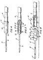
- FIG. 1 is a side view of a contact in accordance with the principles of the invention illustrating the two contact parts prior to assembly;
- FIG. 2 is a side view of the contact in Fig. 1 in assembled condition;
- FIG. 3 is a cross-sectional side view of the assembled contact in Fig. 2;
- FIG. 4 is a side view of the contact of Fig. 2 after crimping;
- FIG. 5 is a cross-sectional side view of the assembled contact in Fig. 4;
- FIG. 6 is a cross-sectional view of a conventional socket which may be formed on the forward end of the second contact part of Figs. 1-3;
- FIG. 7 is a cross-sectional view of the socket end shown in Fig. 6 with a male pin inserted therein, which pin may be formed on the forward end of the second contact part of Figs. 1-3 in lieu of the socket;
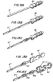
- FIG. 8 is a side view of another preferred embodiment of a contact illustrating the two contact parts prior to assembly;
- FIG. 9 is a perspective view of the first contact part of Fig. 8 showing the stub portion more clearly;
- FIG. 10 is a partial perspective view of the second contact part of Fig. 8 showing the cavity;
- FIG. 11 is a side view of the assembled contact of Fig. 8 after crimping:
- FIG. 12 is a cross-sectional side view of the assembled contact of Fig. 8, and
- FIGS. 13A through E are perspective views of other first contact part configurations.
-
- Referring now to the drawings and more particularity to Fig. 1, there is shown a
contact 10 having a two part construction including a first orattachment member 12 and a second or pin/socket member 14. Thefirst member 12, which is made of an electrically conductive material such as brass, has a round or cylindrically shapedsolid tail 16 along its rearward portion, which is also known in the industry as a PC tail. Thetail 16 has around point 17 at its rearward end and, which facilitates insertion of the PC tail into a printed wiring board connector socket. Theattachment member 12 further, at a medial portion, has anintegral collar 20, which is generally cylindrically shaped. The collar has afront face 22 which slopes rearwardly from the outer extent of the collar to the diameter of the tail. The collar further has a radially extending abutment surface 24 at its forward side which surface is perpendicular to the axis of thetail 16. - At its forward end, the first or
attachment member 12 has a stub portion, generally designated byreference number 30, which extends forwardly from the abutment surface 24. While the stub portion may have a variety of configurations, in this description of the preferred embodiments, the stub portion is formed of acylindrical member 32 which is collinear with thetail 16. The cylindrical member preferably has a plurality of radially extending burrs orprotrusions 34 in the form of ridges, which ridges extend circumferentially around thecylindrical member 32 essentially perpendicular to the axis of thetail 16 andcylindrical member 32. Theridges 34 may have a generally rectangular cross-section with a square corner 36 at the rearward end, an intermediateouter surface 37 and a slopinginward edge 38 at the forward section tapering from a diameter equal the ridge intermediateouter surface 37 and whose forward diameter tapers so as to equal the diameter of the cylindrical stub portion. - The second (or pin/socket)
contact member 14 of thecontact 10 is cylindrically shaped and made of an electrically conductive material such as brass. The rearward end of themember 14 has a blind cavity in the form of a cylindrical opening or bore 40 which is formed along the axis of theattachment member 12 and is sized and shaped to receive thestub portion 30 of thecontact member 12. Thebore 40 is formed from acylindrical wall 42 which has an inner cylindrically shapedwall surface 44 and also anannular shoulder 46 disposed essentially perpendicularly to the axis of theattachment member 14. In the preferred embodiment, the size of thebore 40 is pre-selected to be less than the extent of the burrs and in particular the outer extent of the ridge intermediateouter surface 37 so that an interference fit is formed when the two contact members are joined. - Accordingly, as can be readily seen in Figs. 2 and 3, when the
first contact member 12 is assembled with thesecond member 14, with thestub portion 30, extending into the blind bore 40, the radially extending abutment surface 24 at the rearward side of thecollar 20 abuts theannular shoulder 46 of theattachment member 14. The burrs orridges 34 on thecylindrical member 32 form a tight fit or interference fit with theinner wall surface 44 of the blind bore 40, as is shown with more particularity in Fig. 3. The interference fit formed between the stub and bore wall inhibits any rearward movement of the first member relative to the second member and thus holds the twomembers - In the event that the
bore 44 is not sized to provide an interference fit or if a more secure fit is desired when an interference fit is provided, thecylindrical wall 42 of theattachment member 14 is roll crimped to compress the wall reducing the diameter of the wall with respect to the ridges, as is shown with more particularity in Figs. 4 and 5. In this embodiment, two sections of thecylindrical wall 42 are indented over selected portion of the stub and the ridges. Crimping tools and processes well known in the art may be employed to accomplish the wall compression. This crimping further prevents axial movement of the stub within the blind bore. The forward end of thesecond contact member 14 forms a conventional pin or socket contact (not shown ini Figs. 1-3). - Figs. 6 and 7 illustrate conventional socket and pin contact arrangements which may form the forward section of the second or pin/
socket member 14. Aconventional socket terminal 37, segmented to formtines 37a is formed on theforward end 39 of thesecond contact member 14. A sleeve 41, which may be made of steel, for example, surrounds thesocket terminal 37. Alternatively,pin terminal 43, shown in Fig. 7, may be formed on the forward end of the second contact member. - In another preferred embodiment illustrated in reference to Fig. 8, the first contact member has a rectangular shaped solid pin 16' along its rearward portion, which is also known in the industry as a wire wrap tail. The tail 16' has a triangular point 17' at its rearward end, which facilitates insertion of a wire wrap tool over the tail for wrapping an electrical wire onto the tail. The stub portion 30' of the contact member 12' is formed of an essentially
flat member 50 to provide a polygon shape and extends forwardly along the same axis of tail 16'.Flat member 50 has a plurality of burrs or protrusions 34' in the form of rectangularly shaped barbs 48', which have a rearward flatupstanding side 52 terminating in anupper corner 54, a flat top 56, and a slopingfront side 58, as shown in more particularity in reference to Fig. 9. In this example, fourbarbs 48 are shown in two oppositely disposed pairs. Thefirst contact member 12 further, at a medial portion, has an integral collar 20', which is a flatrectangular portion 60 that is co-planar with theflat member 50. The collar further has anupstanding abutment surface 62 at its forward side which surface is perpendicular to the axis of the tail 16'. - Referring to Fig. 10, the blind cavity 40' in the second contact member 42' is shown as having a polygon or rectangular shape to more clearly match the configuration of the stub portion 30' of the first contact member. It should be noted that the cavity in the second contact member for receiving a flat stub portion like 30' may be cylindrical. However, a cavity which more closely matches the configuration of the stub portion will generally have better retention properties. It should also be noted that while the stub portion 20' of the first contact member 12' (Fig. 9) is shown as having a rectangular shape, it could be formed in a triangular or other polygon shape.
- Referring to Figs. 11 and 12, the two piece contact 10' (Fig. 8) is assembled with the
flat portion 50 of the first contact member 12' extending into acavity 40 of thesecond contact member 14 with theupstanding abutment surface 62 at the forward side of the collar 20' abutting theannular shoulder 46 of thesecond contact member 14. The cavity 40' may have a inner wall 44' which is smaller than the lateral extent of thebarbs 48 such that the barbs form a tight fit with theinner wall 44 of thesecond contact member 14. Alternatively, as shown with more particularity with reference to Fig. 12, the wall 42' of the second contact member 14' may be roll crimped thereby tightening the wall over thebarbs 48 to secure the stub with the bore. In the case where the tail is square for wire wrapping purposes the crimp provides additional resistance to prevent axial and rotational motion of the first contact member with respect to the second contact member. - There has thus been described an improved two piece pin/socket contact which can be reliably assembled on a repetitive basis while saving manufacturing costs. Large quantities of pin/socket contacts can be readily and quickly assembled with any particular tail configuration to suit a customer's needs. Thus, large customer demands for product can be met more quickly and more reliably. Advantageously, one pin or
socket member 14 can be used with a variety of tail and stub configurations, such as those referenced byreference numbers compliant adapter 70 or other configurations. The first contact member 12'''' is shown as having a doublecompliant adapter 70a and aflat sub portion 30". Thestub portion 30" includes radially extendingbarbs 72 havingU-shaped end sections 74 to form outer curved sections 76. Such curved sections will facilitate the insertion of the first contact member 12'''' into a cylindrical cavity in a second contact member. The second contact members (i.e., conventional pin or socket configurations) can be inventoried in mass quantities being suitable to meet a variety of customer demands.
Claims (29)
- A two piece pin/socket contact, comprising:characterized in that,a first member (12) having a tail end (16) and a forwardly extending stub portion (30), a second member (14) having a blind cavity (40) at the rearward end thereof and a pin or socket at the forward end thereof, the stub portion being slidably insertable into the blind cavity,
the stub portion (30) has at least one radially extending protrusion (34) thereon, and the cavity being sized to establish an interference fit between the cavity and the protrusion such that the stub portion is held securely in the cavity. - The invention of claim 1 wherein the cavity is in the form of a cylindrical opening and the stub portion is cylindrically shaped.
- The invention of claim 2 wherein the protrusion on the stub portion comprises a ridge (37) circumscribing the stub portion.
- The invention of claim 3 wherein the ridge Includes a rectangularly shaped section.
- The invention of claim 4 wherein the rectangularly shaped ridge section has a square shaped corner (36) facing the tail end of the first member for digging into the wall of the blind cavity when a force is exerted to pull the first member from the second member.
- The invention of claim 5 wherein the rectangularly shaped section has a downwardly sloping corner (38) extending forwardly of the square shaped corner.
- The invention of claim 4 wherein the second member is crimped to close the cylindrical opening over the protrusion.
- The invention of claim 1 wherein the stub portion of the first member :has a polygon shape.
- The invention of claim 8 wherein the blind cavity of the second member is formed with an inner wall in the shape of a polygon to match the configuration of the stub portion of the first member.
- The invention of claim 8 or 9 wherein the stub portion is essentially flat.
- The invention of claim 10 wherein the protrusion is co-planar with the essentially flat stub.
- The invention of claim 11 wherein the protrusion is essentially rectangularly shaped.
- The invention of claim 10 wherein the second member is crimped to close the cavity over the protrusion.
- The invention of claim 11 wherein the cavity is in the form of a blind bore with an inner cylindrical wall and wherein the protrusion is essentially flat with U-shaped terminal edges providing a curved surface for engaging the inner wall of the blind bore.
- A method for making a connector pin/socket contact according to claim 1, comprising the steps of:providing a first member (12) having a rearwardly extending tail and a forwardly extending stub (30) with at least one radially extending burr (34) thereon;providing a second member (14) with a standardized pin/socket in the front portion thereof, the rear portion defining a blind cavity, the inner wall of which is sized and shaped to receive the stub of the first member; andpressing the stub into the cavity wherein the burr forms an interference fit within the cavity.
- The method according to claim 15 comprising the further step of;crimping the second member adjacent the rear portion bore thereof to close the inner wall of the cavity around the burr.
- The method defined in claim 15 or 16 wherein the cavity is in the form of a cylindrical opening and the stub portion is cylindrically shaped.
- The method defined in claim 17 wherein the protrusions on the stub portion comprises a ridge (37) circumscribing the stub portion.
- The method defined in claim 18 wherein the ridge includes a rectangularly shaped section.
- The method defined in daim 19 wherein the rectangularly shaped ridge section has a square shaped corner (36) facing the tail end of the first member for digging into the wall of the blind cavity when a force is exerted to pull the first member from the second member.
- The method defined in claim 20 wherein the rectangularly shaped section has a downwardly sloping corner (38) extending forwardly of the square shaped corner.
- The method defined in claim 19 wherein the second member is crimped to dose the cylindrical opening over the protrusion.
- The method defined in claim 15 or 16 wherein the stub portion of the first member has a polygon shape.
- The method defined in claim 23 wherein the blind cavity of the second member is formed with an inner wall in the shape of a polygon to match the configuration of the stub portion of the first member.
- The method defined in claim 23 or 24 wherein the stub portion is essentially flat.
- The method defined in claim 25 wherein the protrusion is co-planar with the essentially flat stub.
- The method defined in claim 26 wherein the protrusion is essentially rectangularly shaped.
- The method defined in claim 25 wherein the second member is crimped to close the cavity over the protrusion.
- The method defined in claim 26 wherein the cavity is in the form of a blind bore with an inner cylindrical wall and wherein the protrusion is essentially flat with U-shaped terminal edges providing a curved surface for engaging the inner wall of the blind bore.
Applications Claiming Priority (2)
| Application Number | Priority Date | Filing Date | Title |
|---|---|---|---|
| US53560 | 1998-04-01 | ||
| US09/053,560 US6004172A (en) | 1998-04-01 | 1998-04-01 | Two piece pin/socket contact |
Publications (3)
| Publication Number | Publication Date |
|---|---|
| EP0948088A2 EP0948088A2 (en) | 1999-10-06 |
| EP0948088A3 EP0948088A3 (en) | 2002-03-06 |
| EP0948088B1 true EP0948088B1 (en) | 2005-11-16 |
Family
ID=21985114
Family Applications (1)
| Application Number | Title | Priority Date | Filing Date |
|---|---|---|---|
| EP99302634A Expired - Lifetime EP0948088B1 (en) | 1998-04-01 | 1999-04-01 | Two piece pin/socket contact |
Country Status (6)
| Country | Link |
|---|---|
| US (1) | US6004172A (en) |
| EP (1) | EP0948088B1 (en) |
| CN (1) | CN1131577C (en) |
| DE (1) | DE69928311T2 (en) |
| DK (1) | DK0948088T3 (en) |
| ES (1) | ES2252915T3 (en) |
Families Citing this family (39)
| Publication number | Priority date | Publication date | Assignee | Title |
|---|---|---|---|---|
| BR9915784A (en) * | 1998-12-01 | 2001-09-18 | Thomas & Betts Int | Enhanced two-piece male pin terminal connector |
| DE19922560A1 (en) * | 1999-05-17 | 2000-11-23 | Delphi Tech Inc | Electrical plug |
| US6247940B1 (en) * | 1999-08-23 | 2001-06-19 | Avaya Technology Corp. | Connector having improved high-voltage surge performance |
| ATE251807T1 (en) | 2000-03-30 | 2003-10-15 | Harting Kgaa | ELECTRICAL CONNECTOR FOR CONNECTING ELECTRICAL CONDUCTORS TO AN ELECTRICAL DEVICE |
| DE10022374A1 (en) * | 2000-05-08 | 2001-11-15 | Harting Kgaa | Connector and method of assembling a connector |
| DE10059575C2 (en) * | 2000-11-30 | 2002-11-07 | Compact Dynamics Gmbh | Electrical machine and stator for an electrical machine and manufacturing method therefor |
| US6406313B1 (en) * | 2001-01-04 | 2002-06-18 | Monster Cable Products, Inc. | Interchangeable connector system |
| US6364216B1 (en) * | 2001-02-20 | 2002-04-02 | G&W Electric Co. | Universal power connector for joining flexible cables to rigid devices in any of many configurations |
| US6767260B2 (en) * | 2002-02-28 | 2004-07-27 | Qa Technology Company, Inc. | Hyperboloid electrical contact |
| US6855015B2 (en) * | 2002-07-17 | 2005-02-15 | Teleflex Canada Limited Partnership | Device for rotating with a multisided socket |
| FR2842657B1 (en) * | 2002-07-17 | 2010-02-26 | Framatome Connectors Int | CONNECTING DEVICE BETWEEN A CABLE AND A CONTACT ELEMENT |
| US7976353B2 (en) * | 2006-09-29 | 2011-07-12 | Tyco Electronics Corporation | Two-piece electrical terminal |
| US7422494B2 (en) * | 2006-09-29 | 2008-09-09 | Tyco Electronics Corporation | Two-piece electrical terminal |
| US7766707B2 (en) * | 2007-01-19 | 2010-08-03 | Astec International Limited | Hybrid electrical pins |
| WO2008125922A1 (en) * | 2007-04-12 | 2008-10-23 | Fci | Electrical male terminal |
| SE532190C2 (en) * | 2007-09-25 | 2009-11-10 | Sandvik Intellectual Property | Conductor for electrical resistance elements |
| DE102012002350A1 (en) | 2011-07-20 | 2013-01-24 | Bals Elektrotechnik Gmbh & Co. Kg | Contact element for an electrical connector device |
| EP2830707B1 (en) * | 2012-03-30 | 2016-01-13 | Medtronic Inc. | Medical system lead adapter providing for customized stimulation pattern for a secondary lead |
| US9440692B2 (en) | 2012-07-30 | 2016-09-13 | Cnh Industrial America Llc | Pin assembly for a tracked work vehicle suspension system |
| GB2511042B (en) * | 2013-02-20 | 2014-12-31 | Super Rod Ltd | Improvements in and relating to cable rods |
| US8926361B2 (en) | 2013-03-13 | 2015-01-06 | Carlisle Interconnect Technologies, Inc. | Environmentally sealed contact |
| US9293850B2 (en) * | 2013-07-30 | 2016-03-22 | Hubbell Incorporated (Delaware) | High power electrical connector contact |
| EP2854222B1 (en) | 2013-09-25 | 2020-01-15 | Tyco Electronics Belgium EC BVBA | Two-part electrical contact |
| CN103560346A (en) * | 2013-10-31 | 2014-02-05 | 张家港市凯宝电器有限责任公司 | Column-shaped pin in power supply plug |
| CN104916944A (en) * | 2014-03-14 | 2015-09-16 | 鸿富锦精密工业(武汉)有限公司 | Connector and pin |
| DE102014103864A1 (en) * | 2014-03-20 | 2015-09-24 | Amad Mennekes Holding Gmbh & Co. Kg | Connector assembly in electric vehicles |
| US10027097B1 (en) * | 2014-04-28 | 2018-07-17 | Itool Equipment Holding Llc | Crimp-on single-use lanyard assembly for wire-pulling purposes |
| CN104882694B (en) * | 2015-06-02 | 2018-05-25 | 新昌县南明街道晨升信息咨询服务部 | Soldering turret cable self-tightening quick coupling |
| CN105742889B (en) * | 2016-04-29 | 2018-01-23 | 镇江市润奇电子有限公司 | A kind of radio frequency connector binding post |
| JP6666211B2 (en) * | 2016-07-19 | 2020-03-13 | タイコエレクトロニクスジャパン合同会社 | contact |
| KR101803530B1 (en) | 2016-09-19 | 2017-12-01 | 이경현 | Connector |
| DE102016123162B4 (en) | 2016-11-30 | 2022-05-19 | Lear Corporation | TWO PIECE ELECTRICAL PLUG AND METHOD OF CONNECTING THE SAME |
| CN108448281A (en) * | 2018-03-21 | 2018-08-24 | 菲尼克斯亚太电气(南京)有限公司 | A kind of connector double-body bike contact pin |
| US11121493B2 (en) * | 2019-01-11 | 2021-09-14 | Te Connectivity Corporation | Replaceable pin for terminal of charging inlet assembly |
| CN110381683A (en) * | 2019-07-09 | 2019-10-25 | Oppo(重庆)智能科技有限公司 | Earthing member, shell and electronic device |
| US11258221B2 (en) * | 2019-07-12 | 2022-02-22 | Oliden Technology, Llc | Rotatable and wet-mateable connector |
| CN111009788B (en) * | 2019-12-20 | 2022-03-08 | 北京无线电计量测试研究所 | Assembly structure and connector of axis body and hole body |
| US11476600B2 (en) * | 2020-12-18 | 2022-10-18 | Te Connectivity Solutions Gmbh | Electrical terminals with offset substrate mating portions |
| CN218351760U (en) * | 2022-07-07 | 2023-01-20 | 艾默生电气(铜陵)有限公司 | Sealed terminal assembly |
Family Cites Families (17)
| Publication number | Priority date | Publication date | Assignee | Title |
|---|---|---|---|---|
| US3210720A (en) * | 1961-04-28 | 1965-10-05 | James C Julian | Cable connectors |
| US3149899A (en) * | 1962-04-16 | 1964-09-22 | United Carr Inc | Electrical contact element |
| US3569918A (en) * | 1969-10-30 | 1971-03-09 | Itt | Multipiece electrical contact |
| US3832498A (en) * | 1973-10-09 | 1974-08-27 | E Lawson | Adapter enabling telephone switching equipment terminals to be wire wrapped |
| GB1554265A (en) * | 1975-07-18 | 1979-10-17 | Hughes Aircraft Co | Contact assembly for wire wrap termination |
| US4031614A (en) * | 1975-11-19 | 1977-06-28 | Gte Sylvania Incorporated | Method of making two-piece electrical contact |
| DE3023232A1 (en) * | 1980-06-21 | 1982-01-14 | Harting Elektronik Gmbh, 4992 Espelkamp | Pin or socket contact element - has axial stud and conductor coupling section as sheet metal stamping of U=section with lateral slot |
| US4405195A (en) * | 1981-04-29 | 1983-09-20 | Amp Incorporated | Pin and socket connector |
| US4812129A (en) * | 1987-08-06 | 1989-03-14 | Itt Corporation | Surface mount connector |
| DE4024456A1 (en) * | 1990-08-01 | 1992-02-06 | Dunkel Otto Gmbh | Electric spring contact and bush component - has projecting pin for PCB connection with two stamped-out slots and shoulder limiting depth of insertion |
| US5199911A (en) * | 1991-03-28 | 1993-04-06 | Amp Incorporated | Press fit solder cup |
| US5387138A (en) * | 1991-07-09 | 1995-02-07 | Texas Instruments Incorporated | Printed circuit connector apparatus and method for making same |
| US5439391A (en) * | 1993-02-09 | 1995-08-08 | Ventritex, Inc. | Lead adapter |
| DE4432596A1 (en) * | 1993-09-16 | 1995-03-23 | Whitaker Corp | Modular electrical contact arrangement |
| US5399110A (en) * | 1994-02-04 | 1995-03-21 | General Motors Corporation | Two piece male pin terminal |
| US5492489A (en) * | 1994-06-24 | 1996-02-20 | Chavakula; Anand K. | Four way audio cable adapter |
| FR2759500B1 (en) * | 1997-02-10 | 1999-03-05 | Cinch Connecteurs Sa | MALE ELECTRIC CONTACT MEMBER |
-
1998
- 1998-04-01 US US09/053,560 patent/US6004172A/en not_active Expired - Lifetime
-
1999
- 1999-04-01 DK DK99302634T patent/DK0948088T3/en active
- 1999-04-01 DE DE69928311T patent/DE69928311T2/en not_active Expired - Fee Related
- 1999-04-01 CN CN99103510A patent/CN1131577C/en not_active Expired - Fee Related
- 1999-04-01 EP EP99302634A patent/EP0948088B1/en not_active Expired - Lifetime
- 1999-04-01 ES ES99302634T patent/ES2252915T3/en not_active Expired - Lifetime
Also Published As
| Publication number | Publication date |
|---|---|
| ES2252915T3 (en) | 2006-05-16 |
| DE69928311T2 (en) | 2006-07-27 |
| DE69928311D1 (en) | 2005-12-22 |
| EP0948088A2 (en) | 1999-10-06 |
| DK0948088T3 (en) | 2006-03-06 |
| CN1131577C (en) | 2003-12-17 |
| CN1231529A (en) | 1999-10-13 |
| EP0948088A3 (en) | 2002-03-06 |
| US6004172A (en) | 1999-12-21 |
Similar Documents
| Publication | Publication Date | Title |
|---|---|---|
| EP0948088B1 (en) | Two piece pin/socket contact | |
| US4619496A (en) | Coaxial plug and jack connectors | |
| EP0122700B1 (en) | Coaxial electrical connector for multiple outer conductor coaxial cable | |
| US7226320B2 (en) | Connector having an improved locking structure | |
| US4453796A (en) | Coaxial connector plug | |
| US5716236A (en) | System for terminating the shield of a high speed cable | |
| US8475206B2 (en) | Coaxial connector and method for assembling the same | |
| US5577930A (en) | Electrical connector with improved conductor retention means | |
| US20050266727A1 (en) | Coaxial cable shielding terminal | |
| US20090318019A1 (en) | Electrical connector for terminating a coaxial cable | |
| US5975939A (en) | Twist termination connector | |
| US5064389A (en) | Electrical slave connector | |
| US5536184A (en) | Connector assembly | |
| US6604966B1 (en) | Flexible cable electrical connector | |
| US6305980B2 (en) | Cable end connector having accurately positioned connection terminal therein | |
| JPS60236476A (en) | Diode connector | |
| US6361383B1 (en) | Cable end connector reliably positioning a shell | |
| US20040110427A1 (en) | Cable end connector and method of assembling the same | |
| US6371806B1 (en) | Cable end connector having accurately positioned connection terminal therein | |
| JP3399537B2 (en) | Insulated terminal with integrated body with widened ends | |
| US6340312B1 (en) | Cable end connector having a complete EMI shielding | |
| US6428366B1 (en) | Electrical terminal socket and method of fabricating same | |
| US6416357B1 (en) | Cable end connector with low profile after assembly | |
| US6142795A (en) | Electrical connector with grounded contact | |
| US6340321B2 (en) | Electrical connector |
Legal Events
| Date | Code | Title | Description |
|---|---|---|---|
| PUAI | Public reference made under article 153(3) epc to a published international application that has entered the european phase |
Free format text: ORIGINAL CODE: 0009012 |
|
| AK | Designated contracting states |
Kind code of ref document: A2 Designated state(s): AT BE CH CY DE DK ES FI FR GB GR IE IT LI LU MC NL PT SE Kind code of ref document: A2 Designated state(s): BE CH DE DK ES FR GB IT LI NL SE |
|
| AX | Request for extension of the european patent |
Free format text: AL;LT;LV;MK;RO;SI |
|
| PUAL | Search report despatched |
Free format text: ORIGINAL CODE: 0009013 |
|
| AK | Designated contracting states |
Kind code of ref document: A3 Designated state(s): AT BE CH CY DE DK ES FI FR GB GR IE IT LI LU MC NL PT SE |
|
| AX | Request for extension of the european patent |
Free format text: AL;LT;LV;MK;RO;SI |
|
| 17P | Request for examination filed |
Effective date: 20020902 |
|
| AKX | Designation fees paid |
Free format text: BE CH DE DK ES FR GB IT LI NL SE |
|
| 17Q | First examination report despatched |
Effective date: 20041008 |
|
| GRAP | Despatch of communication of intention to grant a patent |
Free format text: ORIGINAL CODE: EPIDOSNIGR1 |
|
| GRAS | Grant fee paid |
Free format text: ORIGINAL CODE: EPIDOSNIGR3 |
|
| GRAA | (expected) grant |
Free format text: ORIGINAL CODE: 0009210 |
|
| AK | Designated contracting states |
Kind code of ref document: B1 Designated state(s): BE CH DE DK ES FR GB IT LI NL SE |
|
| REG | Reference to a national code |
Ref country code: GB Ref legal event code: FG4D |
|
| REG | Reference to a national code |
Ref country code: CH Ref legal event code: EP |
|
| REF | Corresponds to: |
Ref document number: 69928311 Country of ref document: DE Date of ref document: 20051222 Kind code of ref document: P |
|
| REG | Reference to a national code |
Ref country code: SE Ref legal event code: TRGR |
|
| REG | Reference to a national code |
Ref country code: CH Ref legal event code: NV Representative=s name: PATENTANWAELTE SCHAAD, BALASS, MENZL & PARTNER AG |
|
| REG | Reference to a national code |
Ref country code: DK Ref legal event code: T3 |
|
| REG | Reference to a national code |
Ref country code: ES Ref legal event code: FG2A Ref document number: 2252915 Country of ref document: ES Kind code of ref document: T3 |
|
| ET | Fr: translation filed | ||
| PLBE | No opposition filed within time limit |
Free format text: ORIGINAL CODE: 0009261 |
|
| STAA | Information on the status of an ep patent application or granted ep patent |
Free format text: STATUS: NO OPPOSITION FILED WITHIN TIME LIMIT |
|
| 26N | No opposition filed |
Effective date: 20060817 |
|
| PGFP | Annual fee paid to national office [announced via postgrant information from national office to epo] |
Ref country code: CH Payment date: 20070328 Year of fee payment: 9 |
|
| PGFP | Annual fee paid to national office [announced via postgrant information from national office to epo] |
Ref country code: NL Payment date: 20070403 Year of fee payment: 9 |
|
| PGFP | Annual fee paid to national office [announced via postgrant information from national office to epo] |
Ref country code: SE Payment date: 20070404 Year of fee payment: 9 |
|
| PGFP | Annual fee paid to national office [announced via postgrant information from national office to epo] |
Ref country code: DK Payment date: 20070416 Year of fee payment: 9 |
|
| PGFP | Annual fee paid to national office [announced via postgrant information from national office to epo] |
Ref country code: ES Payment date: 20070521 Year of fee payment: 9 |
|
| PGFP | Annual fee paid to national office [announced via postgrant information from national office to epo] |
Ref country code: BE Payment date: 20070615 Year of fee payment: 9 |
|
| PGFP | Annual fee paid to national office [announced via postgrant information from national office to epo] |
Ref country code: IT Payment date: 20070518 Year of fee payment: 9 |
|
| PGFP | Annual fee paid to national office [announced via postgrant information from national office to epo] |
Ref country code: DE Payment date: 20080411 Year of fee payment: 10 |
|
| BERE | Be: lapsed |
Owner name: *TRI-STAR ELECTRONICS INTERNATIONAL INC. Effective date: 20080430 |
|
| REG | Reference to a national code |
Ref country code: CH Ref legal event code: PL |
|
| REG | Reference to a national code |
Ref country code: DK Ref legal event code: EBP |
|
| EUG | Se: european patent has lapsed | ||
| PGFP | Annual fee paid to national office [announced via postgrant information from national office to epo] |
Ref country code: GB Payment date: 20080402 Year of fee payment: 10 |
|
| NLV4 | Nl: lapsed or anulled due to non-payment of the annual fee |
Effective date: 20081101 |
|
| PG25 | Lapsed in a contracting state [announced via postgrant information from national office to epo] |
Ref country code: NL Free format text: LAPSE BECAUSE OF NON-PAYMENT OF DUE FEES Effective date: 20081101 Ref country code: LI Free format text: LAPSE BECAUSE OF NON-PAYMENT OF DUE FEES Effective date: 20080430 Ref country code: CH Free format text: LAPSE BECAUSE OF NON-PAYMENT OF DUE FEES Effective date: 20080430 |
|
| PG25 | Lapsed in a contracting state [announced via postgrant information from national office to epo] |
Ref country code: BE Free format text: LAPSE BECAUSE OF NON-PAYMENT OF DUE FEES Effective date: 20080430 |
|
| PG25 | Lapsed in a contracting state [announced via postgrant information from national office to epo] |
Ref country code: DK Free format text: LAPSE BECAUSE OF NON-PAYMENT OF DUE FEES Effective date: 20080430 |
|
| REG | Reference to a national code |
Ref country code: ES Ref legal event code: FD2A Effective date: 20080402 |
|
| PG25 | Lapsed in a contracting state [announced via postgrant information from national office to epo] |
Ref country code: ES Free format text: LAPSE BECAUSE OF NON-PAYMENT OF DUE FEES Effective date: 20080402 |
|
| PG25 | Lapsed in a contracting state [announced via postgrant information from national office to epo] |
Ref country code: IT Free format text: LAPSE BECAUSE OF NON-PAYMENT OF DUE FEES Effective date: 20080401 |
|
| GBPC | Gb: european patent ceased through non-payment of renewal fee |
Effective date: 20090401 |
|
| PG25 | Lapsed in a contracting state [announced via postgrant information from national office to epo] |
Ref country code: DE Free format text: LAPSE BECAUSE OF NON-PAYMENT OF DUE FEES Effective date: 20091103 |
|
| PG25 | Lapsed in a contracting state [announced via postgrant information from national office to epo] |
Ref country code: GB Free format text: LAPSE BECAUSE OF NON-PAYMENT OF DUE FEES Effective date: 20090401 |
|
| PG25 | Lapsed in a contracting state [announced via postgrant information from national office to epo] |
Ref country code: SE Free format text: LAPSE BECAUSE OF NON-PAYMENT OF DUE FEES Effective date: 20080402 |
|
| REG | Reference to a national code |
Ref country code: FR Ref legal event code: PLFP Year of fee payment: 18 |
|
| REG | Reference to a national code |
Ref country code: FR Ref legal event code: PLFP Year of fee payment: 19 |
|
| REG | Reference to a national code |
Ref country code: FR Ref legal event code: PLFP Year of fee payment: 20 |
|
| PGFP | Annual fee paid to national office [announced via postgrant information from national office to epo] |
Ref country code: FR Payment date: 20180530 Year of fee payment: 20 |