EP0946791B1 - Elektrochemische gasdiffusionshalbzelle - Google Patents
Elektrochemische gasdiffusionshalbzelle Download PDFInfo
- Publication number
- EP0946791B1 EP0946791B1 EP97948854A EP97948854A EP0946791B1 EP 0946791 B1 EP0946791 B1 EP 0946791B1 EP 97948854 A EP97948854 A EP 97948854A EP 97948854 A EP97948854 A EP 97948854A EP 0946791 B1 EP0946791 B1 EP 0946791B1
- Authority
- EP
- European Patent Office
- Prior art keywords
- gas
- half cell
- electrolyte
- cell according
- modules
- Prior art date
- Legal status (The legal status is an assumption and is not a legal conclusion. Google has not performed a legal analysis and makes no representation as to the accuracy of the status listed.)
- Expired - Lifetime
Links
Images



Classifications
-
- C—CHEMISTRY; METALLURGY
- C25—ELECTROLYTIC OR ELECTROPHORETIC PROCESSES; APPARATUS THEREFOR
- C25B—ELECTROLYTIC OR ELECTROPHORETIC PROCESSES FOR THE PRODUCTION OF COMPOUNDS OR NON-METALS; APPARATUS THEREFOR
- C25B9/00—Cells or assemblies of cells; Constructional parts of cells; Assemblies of constructional parts, e.g. electrode-diaphragm assemblies; Process-related cell features
- C25B9/17—Cells comprising dimensionally-stable non-movable electrodes; Assemblies of constructional parts thereof
- C25B9/19—Cells comprising dimensionally-stable non-movable electrodes; Assemblies of constructional parts thereof with diaphragms
- C25B9/23—Cells comprising dimensionally-stable non-movable electrodes; Assemblies of constructional parts thereof with diaphragms comprising ion-exchange membranes in or on which electrode material is embedded
-
- C—CHEMISTRY; METALLURGY
- C25—ELECTROLYTIC OR ELECTROPHORETIC PROCESSES; APPARATUS THEREFOR
- C25B—ELECTROLYTIC OR ELECTROPHORETIC PROCESSES FOR THE PRODUCTION OF COMPOUNDS OR NON-METALS; APPARATUS THEREFOR
- C25B11/00—Electrodes; Manufacture thereof not otherwise provided for
- C25B11/02—Electrodes; Manufacture thereof not otherwise provided for characterised by shape or form
- C25B11/03—Electrodes; Manufacture thereof not otherwise provided for characterised by shape or form perforated or foraminous
- C25B11/031—Porous electrodes
- C25B11/032—Gas diffusion electrodes
-
- C—CHEMISTRY; METALLURGY
- C25—ELECTROLYTIC OR ELECTROPHORETIC PROCESSES; APPARATUS THEREFOR
- C25B—ELECTROLYTIC OR ELECTROPHORETIC PROCESSES FOR THE PRODUCTION OF COMPOUNDS OR NON-METALS; APPARATUS THEREFOR
- C25B15/00—Operating or servicing cells
- C25B15/02—Process control or regulation
-
- C—CHEMISTRY; METALLURGY
- C25—ELECTROLYTIC OR ELECTROPHORETIC PROCESSES; APPARATUS THEREFOR
- C25B—ELECTROLYTIC OR ELECTROPHORETIC PROCESSES FOR THE PRODUCTION OF COMPOUNDS OR NON-METALS; APPARATUS THEREFOR
- C25B9/00—Cells or assemblies of cells; Constructional parts of cells; Assemblies of constructional parts, e.g. electrode-diaphragm assemblies; Process-related cell features
- C25B9/17—Cells comprising dimensionally-stable non-movable electrodes; Assemblies of constructional parts thereof
- C25B9/19—Cells comprising dimensionally-stable non-movable electrodes; Assemblies of constructional parts thereof with diaphragms
-
- H—ELECTRICITY
- H01—ELECTRIC ELEMENTS
- H01M—PROCESSES OR MEANS, e.g. BATTERIES, FOR THE DIRECT CONVERSION OF CHEMICAL ENERGY INTO ELECTRICAL ENERGY
- H01M4/00—Electrodes
- H01M4/86—Inert electrodes with catalytic activity, e.g. for fuel cells
- H01M4/8605—Porous electrodes
- H01M4/8626—Porous electrodes characterised by the form
-
- Y—GENERAL TAGGING OF NEW TECHNOLOGICAL DEVELOPMENTS; GENERAL TAGGING OF CROSS-SECTIONAL TECHNOLOGIES SPANNING OVER SEVERAL SECTIONS OF THE IPC; TECHNICAL SUBJECTS COVERED BY FORMER USPC CROSS-REFERENCE ART COLLECTIONS [XRACs] AND DIGESTS
- Y02—TECHNOLOGIES OR APPLICATIONS FOR MITIGATION OR ADAPTATION AGAINST CLIMATE CHANGE
- Y02E—REDUCTION OF GREENHOUSE GAS [GHG] EMISSIONS, RELATED TO ENERGY GENERATION, TRANSMISSION OR DISTRIBUTION
- Y02E60/00—Enabling technologies; Technologies with a potential or indirect contribution to GHG emissions mitigation
- Y02E60/30—Hydrogen technology
- Y02E60/50—Fuel cells
Definitions
- gas diffusion electrodes in pressure compensated electrochemical Cells require a subdivision of the gas space into one another with a greater overall height lying segments, so-called gas pockets, in the respective edge area electrically contacted with the electrode and sealed gas-tight have to.
- a half cell that shows such a basic structure is, for example described in German Offenlegungsschrift DE 44 44 114 A1.
- a disadvantage of the construction method shown in DE 44 44 114 is that of comparison cumbersome contacting and sealing of the gas diffusion electrode. It is desired to close the electrode with the gas pocket in the smallest possible space contact and seal to keep the electrode reaction inactive Keep the area of the electrode as small as possible.
- the object of the invention is to provide an electrochemical gas diffusion half cell, the greatest possible utilization of the active electrode area enables, the electrode together with the gas pocket if necessary is designed to be removable in modules so that it is gas-tight in the edge contacts Pre-assembly of the electrode on the gas pocket is enabled, and the electrical contacting for the operation of the gas diffusion electrode in the half cell is simplified.
- Another object of the invention is in particular the half cell and the electrode and gas pocket module so that modules of the half cell also against a conventional electrode, for example a hydrogen producing one Nickel electrode can be replaced in a simple form.
- the object is achieved in that the gas diffusion electrodes equipped gas pockets if necessary also individually from the half cell removable and from their gas supply or pressure compensation as well as from the electrical connections are designed to be detachable.
- the gas pockets manufactured as compact flat elements, the front of which is covered by the gas diffusion electrode is completed so that when the electrode is installed in the half cell no electrolyte in the gas space or no gas in the opposite direction from the gas pocket exit.
- the invention relates to an electrochemical half cell based on a Gas diffusion electrode as cathode or anode with a gas space for the Gas diffusion electrode, which is formed from one or more gas pockets, with an ion exchange membrane, a holding structure for mounting the electrode, electrical connections for the electrode, a gas supply to the gas pocket and a pressure compensating gas discharge to the gas pocket, an electrolyte feed and an electrolyte drain and a housing for receiving the Cell components, which is characterized in that the gas diffusion electrode is connected to the gas pocket to form a module that can be detached from the holding structure is attached, the gas supply and the gas discharge a releasable connection form with the gas bag.
- the gas space can be divided into several gas pockets fed with electrode gas independently of one another, which possibly opposite the electrolyte space located in front of the gas diffusion electrode are pressure compensated.
- a half cell is particularly preferred, in which the case of several gas pocket modules the individual modules independently of one another on the holding structure are releasably attached.
- Embodiments in which the gas diffusion electrodes are also particularly preferred are easily detachably attached to the gas pocket to replace aged ones Allow electrodes.
- the gas supply or the gas discharge is preferably flexible Hose connection executed, with which the gas pocket is connected, the after Loosening the ion exchange membrane facilitates a decrease in the gas pockets.
- the electrical contacting of the gas pocket modules with an external e.g. on The electrical power source connected to the half-cell housing can thereby be improved that the modules in addition to the press contacts in the edge area with the help of a substructure, e.g. pressed with the half-cell housing is from its back, the side facing away from the gas diffusion electrode elastic and electrically conductive contact elements (e.g. spring contacts) electrically are contacted.
- a substructure e.g. pressed with the half-cell housing is from its back, the side facing away from the gas diffusion electrode elastic and electrically conductive contact elements (e.g. spring contacts) electrically are contacted.
- the Gas diffusion electrode on its side facing the gas space of the gas pocket With the help of a support grid electrically contacted on their surface.
- the support grid has thereby electrical contact with the gas pocket rear wall.
- a possible additional gutter which is located at the bottom between the gas diffusion electrode and forms a gas pocket, can be used for recording if necessary Serve condensate.
- the condensate can over along with the excess gas the gas discharge located at the lowest point in the rear electrolyte compartment be removed.
- Electrolyte space with fresh electrolyte can in a preferred variant be avoided that the half cell behind the electrolyte supply has additional electrolyte distributor, the electrolyte flow across the width equalized the half cell.
- the pressure compensating back space is at this version may not flow through.
- the back room stands with the Electrolyte current only connected at the top of the half cell.
- a particular advantage of the construction of the half cell according to the invention is that Possibility of using the half cell even when the gas pocket modules are replaced conventional electrodes, in particular with electrodes producing hydrogen, e.g. To operate nickel electrodes.
- the gas pocket modules interchangeable with conventional electrodes, wherein the gas supply line to the gas pocket can be blocked or dismantled if necessary is.
- the invention also relates to the use of the electrochemical Half cell according to the invention in an electrochemical cell, in particular an electrolysis cell, for optional operation with gas pocket modules or with conventional electrodes, especially with hydrogen producing electrodes, especially activated nickel electrodes.
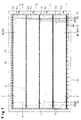
- Figure 1 shows a cross section through a half-cell according to the invention in the viewing direction from the ion exchange membrane to the gas diffusion electrodes and the gas pockets in between.
- Figure 2 corresponding to a broken longitudinal section with the half cell closed the line A-A 'in Figure 1.
- FIG 3 shows a broken longitudinal section along the line A-A 'in Figure 1 with the half cell open with the ion exchange membrane detached from the cell housing and gas pocket module.
- FIG. 4 shows a detail from FIG. 2 to explain the electrical contacting of the Gas bag.
- Figure 5a shows a cross section along the line B-B 'with a view of the gas supply 21 of the half cell.
- Figure 5b shows a partial section along the line C-C 'in the upper part the half cell according to FIG. 1.
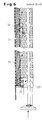
- Figure 6 shows a partial cross section along the line D-D 'in Figure 1 a half-cell, in which the gas pocket modules by a conventional nickel electrode 30 are replaced with the support structure 31.
- FIG. 7 shows a longitudinal section along the line A-A 'of Figure 1 to the 6 variant in operation with a nickel electrode 30.
- An electrochemical half cell is constructed as follows: A frame structure 11 and a substructure 12, which is connected to an external power supply (not shown), are firmly anchored in a half-shell electrolyte-proof housing 13 (see FIG. 3). A gas line 21 (see FIG. 1), an electrolyte feed line 20 and a combined electrolyte and gas discharge line 22 are led into the housing. On the holding structure 11, the gas pocket unit 1 with the gas diffusion electrode 5 im are attached with the aid of vertical clamping bars 8 and horizontal clamping bars 9 Housing 13 attached. The half cell is closed off by the membrane 40, which rests on the circumferential edge of the housing 13 via a seal 41 (see FIG.
- the flexible lines 6a, 6b, 6c, 6d (see FIG. 1) extending from the gas distributor are connected to respective supports 6e on the gas pocket unit via flange connections.
- the embodiment according to FIG. 1 shows a division into four gas pockets 2a, 2b, 2c, 2d with respective pressure compensation via gas overflow lines 7.
- the gas pocket 1 consists of the metallic housing 2, which is connected via current contacts, e.g. Spring contacts 14, brush contacts 15 or direct contact with the live Substructure 12 on arched structural parts 16 (see details in Fig. 4) is connected.
- the further power supply takes place via the metallic Process contacts between the terminal strips 8, 9 and the holding structure 11 via the Edge areas of the housing 2.
- the contact resistance can be e.g. through gilding.
- the gas pocket unit 1 has further supply and discharge lines 6e and 7 for the electrode gas, a support structure 3 to support the gas diffusion electrode 5 and an electrode support grid 4, on which the gas diffusion electrode 5 rests all over.
- Each of the four Gas pockets 1a, 1b, 1c, 1d have one in the edge region of the gas pocket module gas-tightly connected to the gas diffusion electrode 5, which is simultaneously electrical here is connected.
- the gas diffusion electrodes with a conductive back, there is a complete electrical contacting via the electrode support grid.
- the electrolyte comes from the electrolyte feed line 20 through the electrolyte distributor 23 via bores 24 and others Bores 10 in the horizontal terminal strips in the electrolyte space 27 before Gas diffusion electrode 5 a.
- the electrolyte flows through the electrolyte space 27 along the four gas pocket modules la to 1d and flows through holes in the uppermost horizontal terminal block 9 in the electrolyte collecting channel 26.
- the electrolyte flows through holes 25 in the rear space behind the Gas diffusion electrode and is via a downpipe 22 together with excess Electrode gas removed from the half cell (see Fig. 5b).
- the half cell is in operation as an electrolysis cell with an ion exchange membrane on the front 40 closed, for a passage of the ions corresponding to the respective Electrolysis reaction from the half cell according to the invention to one further connected half cell or, if necessary, in the opposite direction worries.
- the electrode gas enters the half-cell at the feed line 21 and is over a gas distributor 19 on the for better gas distribution in the individual gas pocket modules throttled leads 6a, 6b, 6c and 6d to the four gas pocket modules la, 1b, 1c, ld (see Fig. 1) distributed.
- the electrode gas flows through the gas pockets in the longitudinal direction and the unused excess as well Any condensate that has accumulated passes through the gas overflow nozzle at the opposite end 7 from the gas pockets to the electrolyte in the electrolyte gap.
- pressure compensation is achieved. From the gas overflow lines 7 the gas bubbles through the space behind the gas pocket modules above and accumulates in the room above the end of Terminal 22. From there the gas is discharged through the downpipe 22 from the half cell.
- the gas pocket modules can be used with a conventional electrode 1a to 1d together with the terminal strips 8 and 9 as indicated in Fig. 3 be dismantled and by a nickel cathode 30 with a substructure 31, which serves as power supply and support, are replaced.
- the gas supply lines 6a to 6d are reasonably closed.
- the conventional electrode e.g. an activated nickel cathode is with screw connections 32 on the Frame structure 11 of the half cell attached (see Fig. 6 and 7).
- the derivation of the Hydrogen formed in the electrode reaction can be discharged together with Electrolyte take place via the downpipe 22.
Landscapes
- Chemical & Material Sciences (AREA)
- Chemical Kinetics & Catalysis (AREA)
- Electrochemistry (AREA)
- Engineering & Computer Science (AREA)
- Organic Chemistry (AREA)
- Materials Engineering (AREA)
- Metallurgy (AREA)
- General Chemical & Material Sciences (AREA)
- Automation & Control Theory (AREA)
- Electrolytic Production Of Non-Metals, Compounds, Apparatuses Therefor (AREA)
- Hybrid Cells (AREA)
- Fuel Cell (AREA)
- Polysaccharides And Polysaccharide Derivatives (AREA)
- Inert Electrodes (AREA)
- Electrodes For Compound Or Non-Metal Manufacture (AREA)
- Primary Cells (AREA)
Description
In einem halbschaligen elektrolytfesten Gehäuse 13 (siehe Fig. 3) ist eine Rahmenstruktur 11 sowie eine Unterstruktur 12, die mit einer externen Stromzuführung (nicht gezeichnet) verbunden ist, fest verankert. In das Gehäuse durchgeführt sind eine Gasleitung 21 (siehe Fig. 1), eine Elektrolytzuleitung 20 sowie eine kombinierte Elektrolyt- und Gasableitung 22. Auf der Haltestruktur 11 werden mit Hilfe von vertikalen Klemmleisten 8 und horizontalen Klemmleisten 9 die Gastascheneinheit 1 mit der Gasdiffusionselektrode 5 im Gehäuse 13 befestigt. Die Halbzelle wird abgeschlosen durch die Membrane 40, die auf dem umlaufenden Rand des Gehäuses 13 über eine Dichtung 41 anliegt (siehe Fig. 2) und z.B. durch Anflanschen einer weiteren nicht gezeigten Halbzelle elektrolytdicht auf den umlaufenden Rand des Gehäuses 1 gepresst wird. Die von dem Gasverteiler ausgehenden biegsamen Leitungen 6a, 6b, 6c, 6d (siehe Fig. 1) werden über Flanschverbindungen mit jeweiligen Stützen 6e an der Gastascheneinheit verbunden.
Claims (11)
- Elektrochemische Halbzelle auf Basis einer Gasdiffusionselektrode (5) als Kathode oder Anode, mit einem Gasraum für die Gasdiffusionselektrode, der aus einer oder mehreren Gastaschen (2a, 2b, 2c, 2d) gebildet wird, mit einer Ionenaustauschermembran (40), einer Haltestruktur (11), einer Gaszuführung (21) und einer Gasabführung (22), einer Elektrolytzuleitung (20), einer Elektrolytableitung (22) und einem Gehäuse (13), dadurch gekennzeichnet, daß die Gasdiffusionselektrode (5) mit der oder den Gastaschen (1a, 1b, 1c, 1d) zu einem Modul oder mehreren Modulen (1a, 1b, 1c, 1d) verbunden ist, das auf der Haltestruktur (11) lösbar befestigt ist, wobei die Gaszuführung (21) und die Gasabführung (22) eine lösbare Verbindung mit der Gastasche (2a, 2b, 2c, 2d) bilden.
- Halbzelle nach Anspruch 1, dadurch gekennzeichnet, daß der Gasraum in mehrere gegebenenfalls unabhängig voneinander gasbespeiste Gastaschenmodule (la, 1b, lc, ld) aufgeteilt ist, die gegenüber dem Elektrolytraum (27) druckkompensiert sind.
- Halbzelle nach den Anspruch 2, dadurch gekennzeichnet, daß die Gastaschenmodule (1a, 1b, 1c, 1d) unabhängig von einander an der Haltestruktur (11) lösbar befestigt sind.
- Halbzelle nach den Ansprüchen 1 bis 3, dadurch gekennzeichnet, daß die Gaszuführungen (6a, 6b, 6c, 6d) als flexible Schlauchverbindungen mit der Gastasche (2a, 2b, 2c, 2d) ausgebildet sind.
- Halbzelle nach den Ansprüchen 1 bis 4, dadurch gekennzeichnet, daß die Gastaschenmodule (1a, 1b, 1c, 1d) über Strukturelemente (9) in der Halbzelle positioniert, elektrisch kontaktiert und ggf. strömungsmäßig abgedichtet sind, wobei die Strukturelemente gegebenenfalls gleichzeitig einen aktiv durchströmten Elektrolytspalt bilden.
- Halbzelle nach den Ansprüchen 1 bis 5, dadurch gekennzeichnet, daß die Gastaschenmodule (1a, 1b, 1c, 1d) mit der Unterstruktur (12) über Kontaktelemente (14, 15, 16) elektrisch kontaktiert sind.
- Halbzelle nach den Ansprüchen 1 bis 6, dadurch gekennzeichnet, daß die Gasdiffusionselektrode (5) an einem Stützgitter (4) im Innenraum der Gastasche (2a, 2b, 2c, 2d) flächig elektrisch kontaktiert ist.
- Halbzelle nach den Ansprüchen 1 bis 7, dadurch gekennzeichnet, daß die Zelle einen Elektrolytverteiler (23) zur homogenen Versorgung des Elektrolytraumes (27) mit Elektrolyt aufweist.
- Halbzelle nach den Ansprüchen 1 bis 8, dadurch gekennzeichnet, daß die Gastaschenmodule (1a, 1b, 1c, 1d) austauschbar sind gegen konventionelle Elektroden (30)
- Halbzelle nach den Ansprüchen 1 bis 9 dadurch gekennzeichnet, daß die Gasdiffusionselektrode (5) mit den Modulen 1a bis 1d lösbar verbinden ist.
- Verwendung der Halbzelle gemäß einem der Ansprüche 1 bis 10 in einer elektrochemischen Zelle zum wahlweisen Betrieb mit den Gastaschenmodulen (1a, 1b, 1c, 1d) oder mit konventionellen Elektroden (30).
Applications Claiming Priority (3)
| Application Number | Priority Date | Filing Date | Title |
|---|---|---|---|
| DE19646950 | 1996-11-13 | ||
| DE19646950A DE19646950A1 (de) | 1996-11-13 | 1996-11-13 | Elektrochemische Gasdiffusionshalbzelle |
| PCT/EP1997/006030 WO1998021384A1 (de) | 1996-11-13 | 1997-10-31 | Elektrochemische gasdiffusionshalbzelle |
Publications (2)
| Publication Number | Publication Date |
|---|---|
| EP0946791A1 EP0946791A1 (de) | 1999-10-06 |
| EP0946791B1 true EP0946791B1 (de) | 2001-04-11 |
Family
ID=7811577
Family Applications (1)
| Application Number | Title | Priority Date | Filing Date |
|---|---|---|---|
| EP97948854A Expired - Lifetime EP0946791B1 (de) | 1996-11-13 | 1997-10-31 | Elektrochemische gasdiffusionshalbzelle |
Country Status (17)
| Country | Link |
|---|---|
| US (1) | US6251239B1 (de) |
| EP (1) | EP0946791B1 (de) |
| JP (1) | JP3565865B2 (de) |
| KR (1) | KR100457936B1 (de) |
| CN (1) | CN1189598C (de) |
| AT (1) | ATE200521T1 (de) |
| AU (1) | AU714468B2 (de) |
| BR (1) | BR9712764A (de) |
| CA (1) | CA2271297A1 (de) |
| DE (2) | DE19646950A1 (de) |
| ES (1) | ES2156007T3 (de) |
| ID (1) | ID22005A (de) |
| MY (1) | MY132641A (de) |
| NO (1) | NO992307D0 (de) |
| TW (1) | TW396213B (de) |
| WO (1) | WO1998021384A1 (de) |
| ZA (1) | ZA9710180B (de) |
Families Citing this family (16)
| Publication number | Priority date | Publication date | Assignee | Title |
|---|---|---|---|---|
| AUPP790698A0 (en) | 1998-12-23 | 1999-01-28 | Life Therapeutics Limited | Separation of microorganisms |
| AUPP790898A0 (en) | 1998-12-23 | 1999-01-28 | Life Therapeutics Limited | Renal dialysis |
| EP1092789B1 (de) * | 1999-03-31 | 2011-08-10 | Toagosei Co., Ltd. | Elektrolytische zelle mit gasdiffusionselektrode und stromverteilungsverfahren für elektrolytische zelle |
| AUPP971399A0 (en) * | 1999-04-12 | 1999-05-06 | Life Therapeutics Limited | Separation of plasma components |
| US7077942B1 (en) | 1999-12-23 | 2006-07-18 | Gradipore Limited | Removal of biological contaminants |
| AUPQ691400A0 (en) | 2000-04-14 | 2000-05-11 | Life Therapeutics Limited | Separation of micromolecules |
| WO2001078877A1 (en) | 2000-04-18 | 2001-10-25 | Gradipore Limited | Electrophoresis separation and treatment of samples |
| AUPQ697300A0 (en) | 2000-04-18 | 2000-05-11 | Life Therapeutics Limited | Separation apparatus |
| US6923896B2 (en) | 2000-09-22 | 2005-08-02 | The Texas A&M University System | Electrophoresis apparatus and method |
| DE10048299A1 (de) * | 2000-09-29 | 2002-05-29 | Aqua Butzke Werke Gmbh | Vorrichtung zur elektrolytischen Wasserdesinfektion unter Vermeidung katodischer Wasserstoffentwicklung |
| DE10152274A1 (de) * | 2001-10-23 | 2003-04-30 | Bayer Ag | Neue, einzeln herausnehmbare Gastaschen |
| DE10152276A1 (de) * | 2001-10-23 | 2003-04-30 | Bayer Ag | Elektrolysezellen-Halbelement zum Betrieb von Gasdiffusionselektroden mit Trennung der Funktionsräume |
| WO2003035936A2 (de) * | 2001-10-23 | 2003-05-01 | Bayer Materialscience Ag | Elektrochemische halbzelle |
| DE10333853A1 (de) * | 2003-07-24 | 2005-02-24 | Bayer Materialscience Ag | Elektrochemische Zelle |
| JP5818732B2 (ja) * | 2012-03-29 | 2015-11-18 | 旭化成ケミカルズ株式会社 | 電解セル及び電解槽 |
| DE102016224466A1 (de) | 2016-12-08 | 2018-06-14 | Siemens Aktiengesellschaft | Elektrolysezelle oder Elektrodenplatte mit einer Gasdiffusionselektrode und Verfahren zu deren Betrieb |
Family Cites Families (7)
| Publication number | Priority date | Publication date | Assignee | Title |
|---|---|---|---|---|
| US4436608A (en) * | 1982-08-26 | 1984-03-13 | Diamond Shamrock Corporation | Narrow gap gas electrode electrolytic cell |
| US4732660A (en) * | 1985-09-09 | 1988-03-22 | The Dow Chemical Company | Membrane electrolyzer |
| US4657651A (en) * | 1986-04-04 | 1987-04-14 | The Dow Chemical Company | Vertical gas electrode operation |
| US4705614A (en) * | 1986-05-12 | 1987-11-10 | The Dow Chemical Company | Cell with improved electrolyte flow distributor |
| US4744873A (en) * | 1986-11-25 | 1988-05-17 | The Dow Chemical Company | Multiple compartment electrolytic cell |
| DE4444114C2 (de) | 1994-12-12 | 1997-01-23 | Bayer Ag | Elektrochemische Halbzelle mit Druckkompensation |
| DE19622744C1 (de) * | 1996-06-07 | 1997-07-31 | Bayer Ag | Elektrochemische Halbzelle mit Druckkompensation |
-
1996
- 1996-11-13 DE DE19646950A patent/DE19646950A1/de not_active Withdrawn
-
1997
- 1997-10-31 EP EP97948854A patent/EP0946791B1/de not_active Expired - Lifetime
- 1997-10-31 AT AT97948854T patent/ATE200521T1/de not_active IP Right Cessation
- 1997-10-31 ES ES97948854T patent/ES2156007T3/es not_active Expired - Lifetime
- 1997-10-31 CN CNB971996946A patent/CN1189598C/zh not_active Expired - Fee Related
- 1997-10-31 WO PCT/EP1997/006030 patent/WO1998021384A1/de not_active Ceased
- 1997-10-31 DE DE59703368T patent/DE59703368D1/de not_active Expired - Lifetime
- 1997-10-31 CA CA002271297A patent/CA2271297A1/en not_active Abandoned
- 1997-10-31 AU AU71805/98A patent/AU714468B2/en not_active Ceased
- 1997-10-31 US US09/297,206 patent/US6251239B1/en not_active Expired - Fee Related
- 1997-10-31 BR BR9712764-7A patent/BR9712764A/pt not_active IP Right Cessation
- 1997-10-31 ID IDW990319A patent/ID22005A/id unknown
- 1997-10-31 KR KR10-1999-7004183A patent/KR100457936B1/ko not_active Expired - Fee Related
- 1997-10-31 JP JP52210598A patent/JP3565865B2/ja not_active Expired - Fee Related
- 1997-11-11 TW TW086116772A patent/TW396213B/zh not_active IP Right Cessation
- 1997-11-12 MY MYPI97005377A patent/MY132641A/en unknown
- 1997-11-12 ZA ZA9710180A patent/ZA9710180B/xx unknown
-
1999
- 1999-05-12 NO NO992307A patent/NO992307D0/no not_active Application Discontinuation
Also Published As
| Publication number | Publication date |
|---|---|
| KR20000053215A (ko) | 2000-08-25 |
| ATE200521T1 (de) | 2001-04-15 |
| DE19646950A1 (de) | 1998-05-14 |
| JP3565865B2 (ja) | 2004-09-15 |
| DE59703368D1 (de) | 2001-05-17 |
| WO1998021384A1 (de) | 1998-05-22 |
| CN1189598C (zh) | 2005-02-16 |
| KR100457936B1 (ko) | 2004-11-18 |
| AU714468B2 (en) | 2000-01-06 |
| ID22005A (id) | 1999-08-19 |
| NO992307L (no) | 1999-05-12 |
| ZA9710180B (en) | 1998-05-28 |
| AU7180598A (en) | 1998-06-03 |
| ES2156007T3 (es) | 2001-06-01 |
| BR9712764A (pt) | 1999-10-26 |
| CN1238014A (zh) | 1999-12-08 |
| MY132641A (en) | 2007-10-31 |
| US6251239B1 (en) | 2001-06-26 |
| EP0946791A1 (de) | 1999-10-06 |
| NO992307D0 (no) | 1999-05-12 |
| JP2001503562A (ja) | 2001-03-13 |
| CA2271297A1 (en) | 1998-05-22 |
| TW396213B (en) | 2000-07-01 |
Similar Documents
| Publication | Publication Date | Title |
|---|---|---|
| EP0946791B1 (de) | Elektrochemische gasdiffusionshalbzelle | |
| DE69028458T2 (de) | Separatorplatte für Anwendung in einer Gas-Brennstoffzelle, enthaltend einen Satz von Elektroden, und auch eine Brennstoffzellenanlage | |
| DE4444114C2 (de) | Elektrochemische Halbzelle mit Druckkompensation | |
| DE19622744C1 (de) | Elektrochemische Halbzelle mit Druckkompensation | |
| DE60007299T2 (de) | Brennstoffzelle mit kühlsystem basiert auf direkteinspritzung von flüssigem wasser | |
| DE69511585T2 (de) | Seitliche verteileranordnung für elektrochemischen brennstoffzellenstapel | |
| EP0591293B1 (de) | Elektrolysezelle sowie kapillarspaltelektrode für gasentwickelnde oder gasverbrauchende elektrolytische reaktionen und elektrolyseverfahren hierfür | |
| DE10041532A1 (de) | Brennstoffzellenstapel | |
| EP1080511A1 (de) | Brennstoffzellen-modul | |
| DE112007000024T5 (de) | Brennstoffzelle des Festkörperpolymer-Typs | |
| DE2943046C2 (de) | ||
| DE2538000B2 (de) | Bipolare Elektrodenkonstruktion für eine membranlose Elektrolysezelle | |
| DE10234821B4 (de) | Elektrochemische Zelle | |
| EP0175288B1 (de) | Verfahren zum galvanischen Trennen der elektrolytführenden Sammelleitungen von den Elektrolyträumen eines elektro-chemischen Zellenpaketes | |
| DE60306916T2 (de) | Elektrochemischer generator mit einer bipolarplatte, welche eine vielzahl von der verteilung der gase dienenden löchern aufweist | |
| DE1671867B2 (de) | Gasdepolarisiertes galvanisches element mit feinem anodenmaterial | |
| DE60303459T2 (de) | Elektrochemischer membrangenerator | |
| DE10236997B4 (de) | Elektrochemischer Zellenstapel | |
| DE10229820B4 (de) | Gasverteilungsvorrichtung für eine elektrochemische Elektrode und Verfahren zur Reaktionsgasbeaufschlagung einer elektrochemischen Elektrode | |
| DE102020212533A1 (de) | Brennstoffzelle mit reduzierendem Strömungsquerschnitt | |
| AT514871B1 (de) | Batteriezelle | |
| EP1440488A2 (de) | Elektrochemisches halbelement | |
| DE10232331B4 (de) | Brennstoffzellenanordnung | |
| DE102021209557A1 (de) | Brennstoffzelle sowie Brennstoffzellenstapel | |
| DE102019200946A1 (de) | Bipolarplatte für eine Brennstoffzelle und Brennstoffzelle |
Legal Events
| Date | Code | Title | Description |
|---|---|---|---|
| PUAI | Public reference made under article 153(3) epc to a published international application that has entered the european phase |
Free format text: ORIGINAL CODE: 0009012 |
|
| 17P | Request for examination filed |
Effective date: 19990614 |
|
| AK | Designated contracting states |
Kind code of ref document: A1 Designated state(s): AT BE CH DE ES FR GB IT LI NL SE |
|
| GRAG | Despatch of communication of intention to grant |
Free format text: ORIGINAL CODE: EPIDOS AGRA |
|
| GRAG | Despatch of communication of intention to grant |
Free format text: ORIGINAL CODE: EPIDOS AGRA |
|
| GRAH | Despatch of communication of intention to grant a patent |
Free format text: ORIGINAL CODE: EPIDOS IGRA |
|
| 17Q | First examination report despatched |
Effective date: 20000814 |
|
| GRAH | Despatch of communication of intention to grant a patent |
Free format text: ORIGINAL CODE: EPIDOS IGRA |
|
| GRAA | (expected) grant |
Free format text: ORIGINAL CODE: 0009210 |
|
| AK | Designated contracting states |
Kind code of ref document: B1 Designated state(s): AT BE CH DE ES FR GB IT LI NL SE |
|
| REF | Corresponds to: |
Ref document number: 200521 Country of ref document: AT Date of ref document: 20010415 Kind code of ref document: T |
|
| REG | Reference to a national code |
Ref country code: CH Ref legal event code: NV Representative=s name: E. BLUM & CO. PATENTANWAELTE Ref country code: CH Ref legal event code: EP |
|
| GBT | Gb: translation of ep patent filed (gb section 77(6)(a)/1977) |
Effective date: 20010411 |
|
| REF | Corresponds to: |
Ref document number: 59703368 Country of ref document: DE Date of ref document: 20010517 |
|
| ITF | It: translation for a ep patent filed | ||
| REG | Reference to a national code |
Ref country code: ES Ref legal event code: FG2A Ref document number: 2156007 Country of ref document: ES Kind code of ref document: T3 |
|
| ET | Fr: translation filed | ||
| REG | Reference to a national code |
Ref country code: GB Ref legal event code: IF02 |
|
| PLBE | No opposition filed within time limit |
Free format text: ORIGINAL CODE: 0009261 |
|
| STAA | Information on the status of an ep patent application or granted ep patent |
Free format text: STATUS: NO OPPOSITION FILED WITHIN TIME LIMIT |
|
| 26N | No opposition filed | ||
| REG | Reference to a national code |
Ref country code: CH Ref legal event code: PFA Owner name: BAYER AG Free format text: BAYER AG# #51368 LEVERKUSEN (DE) -TRANSFER TO- BAYER AG# #51368 LEVERKUSEN (DE) |
|
| PGFP | Annual fee paid to national office [announced via postgrant information from national office to epo] |
Ref country code: NL Payment date: 20081005 Year of fee payment: 12 |
|
| PGFP | Annual fee paid to national office [announced via postgrant information from national office to epo] |
Ref country code: CH Payment date: 20081117 Year of fee payment: 12 |
|
| PGFP | Annual fee paid to national office [announced via postgrant information from national office to epo] |
Ref country code: ES Payment date: 20081121 Year of fee payment: 12 Ref country code: AT Payment date: 20081013 Year of fee payment: 12 |
|
| PGFP | Annual fee paid to national office [announced via postgrant information from national office to epo] |
Ref country code: BE Payment date: 20081009 Year of fee payment: 12 |
|
| PGFP | Annual fee paid to national office [announced via postgrant information from national office to epo] |
Ref country code: FR Payment date: 20081014 Year of fee payment: 12 |
|
| BERE | Be: lapsed |
Owner name: *BAYER A.G. Effective date: 20091031 |
|
| REG | Reference to a national code |
Ref country code: NL Ref legal event code: V1 Effective date: 20100501 |
|
| REG | Reference to a national code |
Ref country code: CH Ref legal event code: PL |
|
| REG | Reference to a national code |
Ref country code: FR Ref legal event code: ST Effective date: 20100630 |
|
| PG25 | Lapsed in a contracting state [announced via postgrant information from national office to epo] |
Ref country code: NL Free format text: LAPSE BECAUSE OF NON-PAYMENT OF DUE FEES Effective date: 20100501 Ref country code: FR Free format text: LAPSE BECAUSE OF NON-PAYMENT OF DUE FEES Effective date: 20091102 |
|
| PG25 | Lapsed in a contracting state [announced via postgrant information from national office to epo] |
Ref country code: AT Free format text: LAPSE BECAUSE OF NON-PAYMENT OF DUE FEES Effective date: 20091031 |
|
| PG25 | Lapsed in a contracting state [announced via postgrant information from national office to epo] |
Ref country code: LI Free format text: LAPSE BECAUSE OF NON-PAYMENT OF DUE FEES Effective date: 20091031 Ref country code: CH Free format text: LAPSE BECAUSE OF NON-PAYMENT OF DUE FEES Effective date: 20091031 Ref country code: BE Free format text: LAPSE BECAUSE OF NON-PAYMENT OF DUE FEES Effective date: 20091031 |
|
| PGFP | Annual fee paid to national office [announced via postgrant information from national office to epo] |
Ref country code: DE Payment date: 20100923 Year of fee payment: 14 |
|
| PGFP | Annual fee paid to national office [announced via postgrant information from national office to epo] |
Ref country code: IT Payment date: 20101022 Year of fee payment: 14 Ref country code: GB Payment date: 20101027 Year of fee payment: 14 Ref country code: SE Payment date: 20101012 Year of fee payment: 14 |
|
| REG | Reference to a national code |
Ref country code: ES Ref legal event code: FD2A Effective date: 20110408 |
|
| PG25 | Lapsed in a contracting state [announced via postgrant information from national office to epo] |
Ref country code: ES Free format text: LAPSE BECAUSE OF NON-PAYMENT OF DUE FEES Effective date: 20110324 |
|
| PG25 | Lapsed in a contracting state [announced via postgrant information from national office to epo] |
Ref country code: ES Free format text: LAPSE BECAUSE OF NON-PAYMENT OF DUE FEES Effective date: 20091101 |
|
| GBPC | Gb: european patent ceased through non-payment of renewal fee |
Effective date: 20111031 |
|
| REG | Reference to a national code |
Ref country code: SE Ref legal event code: EUG |
|
| PG25 | Lapsed in a contracting state [announced via postgrant information from national office to epo] |
Ref country code: DE Free format text: LAPSE BECAUSE OF NON-PAYMENT OF DUE FEES Effective date: 20120501 |
|
| REG | Reference to a national code |
Ref country code: DE Ref legal event code: R119 Ref document number: 59703368 Country of ref document: DE Effective date: 20120501 |
|
| PG25 | Lapsed in a contracting state [announced via postgrant information from national office to epo] |
Ref country code: IT Free format text: LAPSE BECAUSE OF NON-PAYMENT OF DUE FEES Effective date: 20111031 Ref country code: GB Free format text: LAPSE BECAUSE OF NON-PAYMENT OF DUE FEES Effective date: 20111031 |
|
| PG25 | Lapsed in a contracting state [announced via postgrant information from national office to epo] |
Ref country code: SE Free format text: LAPSE BECAUSE OF NON-PAYMENT OF DUE FEES Effective date: 20111101 |