EP0945838A1 - Remote controlling device for operative machines - Google Patents
Remote controlling device for operative machines Download PDFInfo
- Publication number
- EP0945838A1 EP0945838A1 EP98115032A EP98115032A EP0945838A1 EP 0945838 A1 EP0945838 A1 EP 0945838A1 EP 98115032 A EP98115032 A EP 98115032A EP 98115032 A EP98115032 A EP 98115032A EP 0945838 A1 EP0945838 A1 EP 0945838A1
- Authority
- EP
- European Patent Office
- Prior art keywords
- receiver
- controlling device
- remote controlling
- transmitter
- section
- Prior art date
- Legal status (The legal status is an assumption and is not a legal conclusion. Google has not performed a legal analysis and makes no representation as to the accuracy of the status listed.)
- Granted
Links
Images
Classifications
-
- G—PHYSICS
- G08—SIGNALLING
- G08C—TRANSMISSION SYSTEMS FOR MEASURED VALUES, CONTROL OR SIMILAR SIGNALS
- G08C17/00—Arrangements for transmitting signals characterised by the use of a wireless electrical link
- G08C17/02—Arrangements for transmitting signals characterised by the use of a wireless electrical link using a radio link
-
- G—PHYSICS
- G08—SIGNALLING
- G08C—TRANSMISSION SYSTEMS FOR MEASURED VALUES, CONTROL OR SIMILAR SIGNALS
- G08C25/00—Arrangements for preventing or correcting errors; Monitoring arrangements
-
- G—PHYSICS
- G08—SIGNALLING
- G08C—TRANSMISSION SYSTEMS FOR MEASURED VALUES, CONTROL OR SIMILAR SIGNALS
- G08C2201/00—Transmission systems of control signals via wireless link
- G08C2201/60—Security, fault tolerance
- G08C2201/63—Redundant transmissions
Abstract
Description
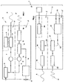
- fig. 1 shows the block diagram of the transmitter;
- fig. 2 shows the block diagram of the receiver.
- emergency stopping of the machine;
- lifting - lowering of the left level;
- opening - closing of the left enlargement;
- returning action of the left auger;
- reversal of the left auger;
- returning action of the left strip;
- lifting - lowering of the right level;
- opening - closing of the right enlargement;
- returning action of the right auger;
- reversal of the right auger;
- returning action of the right strip;
- laying of the tamper turns;
- laying of the pressure of the front traction.
Claims (8)
- Remote controlling device (1) of an operative machine comprising a transmitter (2) arranged on the ground at the disposal of an operator and a receiver (3) inboard and supplied with at least an accomplishment circuit (24) connected with the drives (25) of the machine itself, characterised in that said transmitter (2) comprises a first transmitting section (2') of luminous infrared waves (6) and a second transmitting section (2'') of electromagnetic waves (17) which cooperate with said receiver (3) which comprises a first receiving section (3') of luminous infrared waves (6) and a second receiving station (3'') of said electromagnetic waves (17), said receiver (3) presenting electronic means (19) suitable for realising a permission signal (20) for the activation of said accomplishment circuit (24) only if said first receiving section (3') receives said luminous infrared waves (6) emitted by said first transmitting section (2').
- Remote controlling device (1) according to the claim 1) characterised in that said first transmitting section (2') comprises a empowering circuit (5) activable by an outer drive electrically connected with a generator of luminous infrared waves (7), being this one electrically connected with a transmitter of infrared waves (8) suitable for generating luminous infrared waves (6).
- Remote controlling device (1) according to the claim 1) characterised in that said second transmitting section (2'') comprises a frequency generator (9) connected with a modulator (13), this one cooperating with a radio transmitter (16) with which it is electrically connected, suitable for generating electromagnetic waves (17).
- Remote controlling device (1) according to the claim 3) characterised in that said modulator (13) is connected with the output of a unit of the input of the commands (11) commanded by outer keys of command (10).
- Remote controlling device (1) according to the claim 1) characterised in that said first receiving section (3') comprises a receiver of luminous infrared waves (18) connected with a detector (19).
- Remote controlling device (1) according to the claim 1) characterised in that said second receiving section (3'') comprises a receiver (22) of electromagnetic waves connected with at least an accomplishment circuit (24) suitable for activating the drives (25) of said machine.
- Remote controlling device (1) according to the claim 6) characterised in that said at least an accomplishment circuit (24) is connected at the output of a demodulator (21), this one presenting the input connected with the output of said receiver (22).
- Remote controlling device (1) according to the claim 1) characterised in that said receiver (3) presents a feeder (26) electrically connected with a generator (27) of said operative machine.
Applications Claiming Priority (2)
| Application Number | Priority Date | Filing Date | Title |
|---|---|---|---|
| ITVI980062 | 1998-03-27 | ||
| IT98VI000062A ITVI980062A1 (en) | 1998-03-27 | 1998-03-27 | REMOTE CONTROL DEVICE FOR OPERATING MACHINES |
Publications (2)
| Publication Number | Publication Date |
|---|---|
| EP0945838A1 true EP0945838A1 (en) | 1999-09-29 |
| EP0945838B1 EP0945838B1 (en) | 2009-12-23 |
Family
ID=11426650
Family Applications (1)
| Application Number | Title | Priority Date | Filing Date |
|---|---|---|---|
| EP98115032A Expired - Lifetime EP0945838B1 (en) | 1998-03-27 | 1998-08-11 | Remote controlling device for operative machines |
Country Status (4)
| Country | Link |
|---|---|
| US (1) | US6750780B1 (en) |
| EP (1) | EP0945838B1 (en) |
| DE (1) | DE69841402D1 (en) |
| IT (1) | ITVI980062A1 (en) |
Cited By (3)
| Publication number | Priority date | Publication date | Assignee | Title |
|---|---|---|---|---|
| ES2161603A1 (en) * | 1999-04-19 | 2001-12-01 | Iglesias Angel Sa | Limitation system of the area of operations for cranes, bridge-cranes and the like by radio control |
| EP1288882A1 (en) * | 2001-08-28 | 2003-03-05 | Collard Belgium Electronics | Remote control system |
| US20150054629A1 (en) * | 2013-08-26 | 2015-02-26 | Wacker Neuson Production Americas Llc | System for controlling remote operation of ground working devices |
Families Citing this family (9)
| Publication number | Priority date | Publication date | Assignee | Title |
|---|---|---|---|---|
| EP1748399A1 (en) * | 2005-07-28 | 2007-01-31 | Savoie Electronique Groupe Sabatier | Security remote control device |
| US20070025554A1 (en) * | 2005-08-01 | 2007-02-01 | Ping-Wen Ong | Remote control association methodology |
| US8970363B2 (en) | 2006-09-14 | 2015-03-03 | Crown Equipment Corporation | Wrist/arm/hand mounted device for remotely controlling a materials handling vehicle |
| CN102157056B (en) | 2006-09-14 | 2012-12-05 | 克朗设备公司 | Systems and methods of remotely controlling a materials handling vehicle |
| CN101493685A (en) * | 2008-01-21 | 2009-07-29 | 鸿富锦精密工业(深圳)有限公司 | Wireless hand-operated wheel |
| US9522817B2 (en) | 2008-12-04 | 2016-12-20 | Crown Equipment Corporation | Sensor configuration for a materials handling vehicle |
| WO2020159636A1 (en) | 2019-02-01 | 2020-08-06 | Crown Equipment Corporation | Pairing a remote control device to a vehicle |
| US11641121B2 (en) | 2019-02-01 | 2023-05-02 | Crown Equipment Corporation | On-board charging station for a remote control device |
| AU2021325685B2 (en) | 2020-08-11 | 2024-04-04 | Crown Equipment Corporation | Remote control device |
Citations (3)
| Publication number | Priority date | Publication date | Assignee | Title |
|---|---|---|---|---|
| US3641575A (en) * | 1970-03-12 | 1972-02-08 | Gen Signal Corp | Remote control apparatus |
| US4904993A (en) * | 1986-05-16 | 1990-02-27 | Alps Electric Co., Ltd. | Remote control apparatus with selectable RF and optical signal transmission |
| EP0514244A1 (en) * | 1991-05-07 | 1992-11-19 | Jay Electronique | Installation for remote control of a motorized mobile engine |
Family Cites Families (7)
| Publication number | Priority date | Publication date | Assignee | Title |
|---|---|---|---|---|
| US4827395A (en) * | 1983-04-21 | 1989-05-02 | Intelli-Tech Corporation | Manufacturing monitoring and control systems |
| US4916532A (en) * | 1987-09-15 | 1990-04-10 | Jerry R. Iggulden | Television local wireless transmission and control |
| JPH01156640U (en) * | 1988-04-19 | 1989-10-27 | ||
| US5227780A (en) * | 1989-03-16 | 1993-07-13 | Houston Satellite Systems, Inc. | Apparatus with a portable UHF radio transmitter remote for controlling one or more of infrared controlled appliances |
| US5659883A (en) * | 1992-08-24 | 1997-08-19 | General Instrument Corporation | Selection between separately received messages in diverse-frequency remote-control communication system |
| US5383044B1 (en) * | 1992-09-18 | 1998-09-01 | Recoton Corp | Systems methods and apparatus for transmitting radio frequency remote control signals |
| US6396612B1 (en) * | 1998-02-11 | 2002-05-28 | Telefonaktiebolaget L M Ericsson | System, method and apparatus for secure transmission of confidential information |
-
1998
- 1998-03-27 IT IT98VI000062A patent/ITVI980062A1/en unknown
- 1998-08-11 DE DE69841402T patent/DE69841402D1/en not_active Expired - Lifetime
- 1998-08-11 EP EP98115032A patent/EP0945838B1/en not_active Expired - Lifetime
-
1999
- 1999-03-15 US US09/267,689 patent/US6750780B1/en not_active Expired - Fee Related
Patent Citations (3)
| Publication number | Priority date | Publication date | Assignee | Title |
|---|---|---|---|---|
| US3641575A (en) * | 1970-03-12 | 1972-02-08 | Gen Signal Corp | Remote control apparatus |
| US4904993A (en) * | 1986-05-16 | 1990-02-27 | Alps Electric Co., Ltd. | Remote control apparatus with selectable RF and optical signal transmission |
| EP0514244A1 (en) * | 1991-05-07 | 1992-11-19 | Jay Electronique | Installation for remote control of a motorized mobile engine |
Non-Patent Citations (1)
| Title |
|---|
| WEBER ET AL: "Ein tragbares Funk-Fernsteuergerät für Gewinnungsmaschinen", GLUCKAUF., 13 July 1967 (1967-07-13), ESSEN DE, pages 375 - 378, XP002093388 * |
Cited By (6)
| Publication number | Priority date | Publication date | Assignee | Title |
|---|---|---|---|---|
| ES2161603A1 (en) * | 1999-04-19 | 2001-12-01 | Iglesias Angel Sa | Limitation system of the area of operations for cranes, bridge-cranes and the like by radio control |
| EP1288882A1 (en) * | 2001-08-28 | 2003-03-05 | Collard Belgium Electronics | Remote control system |
| US20150054629A1 (en) * | 2013-08-26 | 2015-02-26 | Wacker Neuson Production Americas Llc | System for controlling remote operation of ground working devices |
| EP2843637A1 (en) * | 2013-08-26 | 2015-03-04 | Wacker Neuson Production Americas LLC | System for controlling remote operation of ground working devices |
| EP2843637B1 (en) | 2013-08-26 | 2016-06-08 | Wacker Neuson Production Americas LLC | System for controlling remote operation of ground working devices |
| US9650062B2 (en) | 2013-08-26 | 2017-05-16 | Wacker Neuson Production Americas Llc | System for controlling remote operation of ground working devices |
Also Published As
| Publication number | Publication date |
|---|---|
| US6750780B1 (en) | 2004-06-15 |
| ITVI980062A1 (en) | 1999-09-27 |
| EP0945838B1 (en) | 2009-12-23 |
| DE69841402D1 (en) | 2010-02-04 |
Similar Documents
| Publication | Publication Date | Title |
|---|---|---|
| EP0945838A1 (en) | Remote controlling device for operative machines | |
| US4507646A (en) | Radio communication system | |
| JP2742960B2 (en) | Wired / wireless remote control device | |
| US5450068A (en) | Infrared remote control for soil compacting devices | |
| JPH06317659A (en) | Automatic car identification system, body identification and method of position judgement | |
| EP0976879A4 (en) | Remote radio operating system, and remote operating apparatus, mobile relay station and radio mobile working machine | |
| EP1158691A3 (en) | Repeater for transmission system for controlling and determining the status of electrical devices from remote locations | |
| SE9101208L (en) | REMOTE MANAGEMENT SYSTEM BEFORE LAST | |
| RU2204200C2 (en) | Mobile communication device and radio receiver for coupling with such mobile communication device | |
| CA2058330A1 (en) | A system and method for the non-contact transmission of data | |
| AU2576597A (en) | System and method for transmitting information for amphibious travelin g vehicle and system for controlling operation of the vehicle | |
| GB2265652A (en) | Mine communication system | |
| JP2004017223A (en) | Robot controlling device | |
| JP2002345058A (en) | Remote control device for working machine | |
| JP3809914B2 (en) | Remote control method of unmanned work vehicle | |
| GB2271692A (en) | Vehicle location system | |
| JP2000165970A (en) | Radio remote control system for opening and closing switch for building opening, antenna unit and switching control unit | |
| EP0328796A2 (en) | System for transmitting information between automatically guided vehicles and ground control systems by means of electromagnetic induction | |
| EP0914720B1 (en) | Information link | |
| JPH03504403A (en) | Control device for moving objects | |
| JP2000049677A (en) | Communication equipment for construction site | |
| US20010022818A1 (en) | Work machine control system | |
| JP2605625B2 (en) | Portable satellite communication earth station equipment | |
| JPS63145151A (en) | Wireless remote control system | |
| JPH07317107A (en) | Damage preventive method of underground buried object in excavation |
Legal Events
| Date | Code | Title | Description |
|---|---|---|---|
| PUAI | Public reference made under article 153(3) epc to a published international application that has entered the european phase |
Free format text: ORIGINAL CODE: 0009012 |
|
| AK | Designated contracting states |
Kind code of ref document: A1 Designated state(s): DE ES FI FR GB IT PT SE |
|
| AX | Request for extension of the european patent |
Free format text: AL;LT;LV;MK;RO;SI |
|
| 17P | Request for examination filed |
Effective date: 20000126 |
|
| AKX | Designation fees paid |
Free format text: DE ES FI FR GB IT PT SE |
|
| AXX | Extension fees paid |
Free format text: SI PAYMENT 20000126 |
|
| RAP1 | Party data changed (applicant data changed or rights of an application transferred) |
Owner name: CATERPILLAR PAVING PRODUCTS INC. |
|
| 17Q | First examination report despatched |
Effective date: 20071005 |
|
| GRAP | Despatch of communication of intention to grant a patent |
Free format text: ORIGINAL CODE: EPIDOSNIGR1 |
|
| GRAS | Grant fee paid |
Free format text: ORIGINAL CODE: EPIDOSNIGR3 |
|
| GRAA | (expected) grant |
Free format text: ORIGINAL CODE: 0009210 |
|
| AK | Designated contracting states |
Kind code of ref document: B1 Designated state(s): DE ES FI FR GB IT PT SE |
|
| AX | Request for extension of the european patent |
Extension state: SI |
|
| REG | Reference to a national code |
Ref country code: GB Ref legal event code: FG4D |
|
| REF | Corresponds to: |
Ref document number: 69841402 Country of ref document: DE Date of ref document: 20100204 Kind code of ref document: P |
|
| PG25 | Lapsed in a contracting state [announced via postgrant information from national office to epo] |
Ref country code: SE Free format text: LAPSE BECAUSE OF FAILURE TO SUBMIT A TRANSLATION OF THE DESCRIPTION OR TO PAY THE FEE WITHIN THE PRESCRIBED TIME-LIMIT Effective date: 20091223 Ref country code: FI Free format text: LAPSE BECAUSE OF FAILURE TO SUBMIT A TRANSLATION OF THE DESCRIPTION OR TO PAY THE FEE WITHIN THE PRESCRIBED TIME-LIMIT Effective date: 20091223 |
|
| PG25 | Lapsed in a contracting state [announced via postgrant information from national office to epo] |
Ref country code: PT Free format text: LAPSE BECAUSE OF FAILURE TO SUBMIT A TRANSLATION OF THE DESCRIPTION OR TO PAY THE FEE WITHIN THE PRESCRIBED TIME-LIMIT Effective date: 20100423 Ref country code: ES Free format text: LAPSE BECAUSE OF FAILURE TO SUBMIT A TRANSLATION OF THE DESCRIPTION OR TO PAY THE FEE WITHIN THE PRESCRIBED TIME-LIMIT Effective date: 20100403 |
|
| PLBE | No opposition filed within time limit |
Free format text: ORIGINAL CODE: 0009261 |
|
| STAA | Information on the status of an ep patent application or granted ep patent |
Free format text: STATUS: NO OPPOSITION FILED WITHIN TIME LIMIT |
|
| 26N | No opposition filed |
Effective date: 20100924 |
|
| GBPC | Gb: european patent ceased through non-payment of renewal fee |
Effective date: 20100811 |
|
| PG25 | Lapsed in a contracting state [announced via postgrant information from national office to epo] |
Ref country code: GB Free format text: LAPSE BECAUSE OF NON-PAYMENT OF DUE FEES Effective date: 20100811 |
|
| PGFP | Annual fee paid to national office [announced via postgrant information from national office to epo] |
Ref country code: FR Payment date: 20120809 Year of fee payment: 15 Ref country code: DE Payment date: 20120831 Year of fee payment: 15 |
|
| PGFP | Annual fee paid to national office [announced via postgrant information from national office to epo] |
Ref country code: IT Payment date: 20130819 Year of fee payment: 16 |
|
| PG25 | Lapsed in a contracting state [announced via postgrant information from national office to epo] |
Ref country code: DE Free format text: LAPSE BECAUSE OF NON-PAYMENT OF DUE FEES Effective date: 20140301 |
|
| REG | Reference to a national code |
Ref country code: DE Ref legal event code: R119 Ref document number: 69841402 Country of ref document: DE Effective date: 20140301 |
|
| REG | Reference to a national code |
Ref country code: FR Ref legal event code: ST Effective date: 20140430 |
|
| PG25 | Lapsed in a contracting state [announced via postgrant information from national office to epo] |
Ref country code: FR Free format text: LAPSE BECAUSE OF NON-PAYMENT OF DUE FEES Effective date: 20130902 |
|
| PG25 | Lapsed in a contracting state [announced via postgrant information from national office to epo] |
Ref country code: IT Free format text: LAPSE BECAUSE OF NON-PAYMENT OF DUE FEES Effective date: 20140811 |