EP0945708A2 - Instrument indiquant la trajectoire de vol - Google Patents
Instrument indiquant la trajectoire de vol Download PDFInfo
- Publication number
- EP0945708A2 EP0945708A2 EP99200397A EP99200397A EP0945708A2 EP 0945708 A2 EP0945708 A2 EP 0945708A2 EP 99200397 A EP99200397 A EP 99200397A EP 99200397 A EP99200397 A EP 99200397A EP 0945708 A2 EP0945708 A2 EP 0945708A2
- Authority
- EP
- European Patent Office
- Prior art keywords
- flight path
- aircraft
- image combining
- display
- target
- Prior art date
- Legal status (The legal status is an assumption and is not a legal conclusion. Google has not performed a legal analysis and makes no representation as to the accuracy of the status listed.)
- Withdrawn
Links
Images
Classifications
-
- G—PHYSICS
- G01—MEASURING; TESTING
- G01C—MEASURING DISTANCES, LEVELS OR BEARINGS; SURVEYING; NAVIGATION; GYROSCOPIC INSTRUMENTS; PHOTOGRAMMETRY OR VIDEOGRAMMETRY
- G01C23/00—Combined instruments indicating more than one navigational value, e.g. for aircraft; Combined measuring devices for measuring two or more variables of movement, e.g. distance, speed or acceleration
- G01C23/005—Flight directors
-
- G—PHYSICS
- G02—OPTICS
- G02B—OPTICAL ELEMENTS, SYSTEMS OR APPARATUS
- G02B27/00—Optical systems or apparatus not provided for by any of the groups G02B1/00 - G02B26/00, G02B30/00
- G02B27/01—Head-up displays
Definitions
- the present invention relates to a flight path display apparatus which displays a flight path on a head-up display installed in a cockpit of an aircraft.
- a head-up display unit which is mounted in front of a canopy of a cockpit of an aircraft and has an image combining panel through which the light from the outside view and projected information of the aircraft data are combined, so that a pilot can obtain the aircraft flight data information while seeing the outside view.
- flight path display apparatus which indicates a target flight path by superimposing on the image combining panel of the head-up display to assist the pilot in landing to an airport for example.
- the pilot can land safely even under low visibility due to bad weather by controlling the aircraft so as to fly along this indicated flight path.
- the aircraft is a fixed wing aircraft, for example, an approach course to an airport is straight approach and an approach angle is about 3°.
- an approach course of a helicopter is not a simple straight approach but is an approach of a three-dimensional curve and an approach angle also varies considerably from 3° to 12° because it has to approach while avoiding slapping noise and also avoiding flight paths of other aircraft for example.
- It is also difficult to enlarge the area of the image combining panel of the head-up display unit because the cockpit of the helicopter is narrow and the equipment thereof must be small. Accordingly, the field of view of the existing head-up display unit is very narrow.
- the helicopter can change the flight direction easily, there has been a problem that the target flight path is gone outside of the image combining panel and is lost when the aircraft nose is pointing some different direction from the target flight path even if it is flying near the target flight path. Such circumstance becomes a big problem under low visibility, e.g., when the ground surface is not visible in particular.
- the invention provides a flight path display apparatus comprising:
- the target flight path is projected on the image combining panel of the head-up display unit.
- This target flight path image is calculated based on the position and attitude of the aircraft obtained from the aircraft flight data measuring means and based on the predetermined flight path data and is indicated on the image combining panel which is provided in front of a pilot head with being superimposed on the outside view. Accordingly, the pilot can control the aircraft along the indicated target flight path while looking forward. It also allows the pilot to control the aircraft along the target flight path even under low visibility condition.
- the displayed position of the target flight path image is gone outside of the display area of the image combining panel.
- the direction toward the target flight path from the center of the display area of the image combining panel is indicated on the image combining panel by the target mark.
- the target flight path image appears on the image combining panel by turning the aircraft in the direction indicated by this target mark.
- the pilot can find the target flight path readily without losing it even when no target flight path image is displayed on the image combining panel under low visibility.
- the computing means calculates a distance between the target flight path and the aircraft position and changes the display pattern corresponding to the distance.
- the display pattern is changed corresponding to the distance between the aircraft position and the target flight path, so that the pilot can readily understand the distance to the target flight path, thus reducing the workload, even when the target flight path is not indicated on the image combining panel.
- the target flight path image is composed of a plurality of path marks and each path mark inclines corresponding to the attitude of the aircraft supposed when the aircraft is positioned at each path mark.
- each path mark of the target flight path image inclines corresponding to the supposed attitude of the aircraft, e.g., the bank angle, as described above, so that the pilot can fly the aircraft along the flight path by controlling so that the bank angle of the aircraft coincides with each indicated path mark.
- a turn mark indicative of an angle of turn is indicated on the image combining panel.
- the pilot can understand the angle of turn and can anticipate the turn ending position from that even if the flight path turns significantly and a turn ending position is gone outside of the display area of the image combining panel. Thereby, the workload of the pilot can be reduced.
- the computing means calculates a distance between a landing spot and the aircraft and erases the display of the image combining panel when the distance becomes shorter than a predetermined distance.
- the display of the image combining panel is erased when the aircraft approaches to the landing spot.
- the pilot lands visually by contact flight when the aircraft approaches near to the landing spot and the landing spot is visible.
- the display image of the head-up display unit might become annoying in contrary in such a case, such annoyance is removed and the pilot workload during landing may be reduced by the invention because the display of the image combining panel is erased when the distance between the landing spot and the aircraft becomes shorter than the predetermined distance.
- the pilot is allowed to erase some part of the display of the image combining panel selectively.
- the pilot can erase the display selectively, so that it is possible to show the flight path clearly by erasing a display of heading when the path marks overlap with the display of heading and the target flight path is hardly recognized for example.
- a relative positional relationship between the position of the aircraft and a landing/take-off spot and a landing/take-off flight path are displayed on the side of an altitude indicating section of the image combining panel during landing/taking off, and the landing/take-off spot is displayed at the edge of the display area on the side of the landing/take-off spot when the landing/take-off spot is gone outside of the display area of the image combining panel.
- the display apparatus allows the pilot to readily understand the relative positional relationship between the position of the aircraft and the landing/take-off spot even when the landing/take-off spot is gone outside of the display area, so that the workload of the pilot may be reduced during landing/take-off operation from a rooftop heli-spot for example.
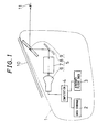
- Fig. 1 is a block diagram showing the structure of a flight path display apparatus 1 according to one embodiment of the present invention.
- the flight path display apparatus 1 is installed in a cockpit of a helicopter and comprises data storage means 2, aircraft flight data measuring means 3, computing means 4 and a head-up display unit 5.
- the data storage means 2 is provided in a FMC (Flight Management Computer) and stores flight path data of predetermined flight paths.
- flight path data may be an approach path to an airport given from a landing assisting system of the landing airport for another example.
- the aircraft flight data measuring means 3 has an attitude indicator and a navigation system.
- the attitude indicator measures attitude data such as pitch angle and wing roll (bank) angle by a gyroscope and the navigation system measures aircraft flight data such as a position, flight direction (heading of the aircraft), distance and other data of the aircraft measured by GPS for example.
- the head-up display unit 5 has projecting means 6, a relay lens 7, a reflecting mirror 8 and an image combining panel 9.
- the projecting means 6 projects an image on the image combining panel 9 via the relay lens 7 and the reflecting mirror 8.
- the image combining panel 9, which is called, for example, a combiner, is disposed inside a canopy 10 in front of a pilot head.
- the image combining panel 9 reflects only light of a specific wavelength and penetrates other wavelength, therefore through which a pilot 11 can see outside view. Accordingly, a pilot 11 can visually perceive the image of the aircraft data from the projecting means 6, which projects light of a specific wavelength, while superimposing the outside view on the image combining panel 9.
- the computing means 4 calculates the altitude, speed and heading of the aircraft to be indicated based on the aircraft flight data to indicate on the image combining panel 9 and calculates the position of the target flight path to be indicated on the image combining panel 9 based on the predetermined flight path data stored in the storage means 2 to display the target flight path on the image combining panel 9 as an image.
- the pilot 11 allows the pilot 11 to visually perceive the aircraft data through the image combining panel 9 while looking forward and seeing the outside without looking down flight instruments on the instrument panel which is installed below a canopy 10, and the control of the pilot is facilitated by superimposing the image of the target flight path to be followed on the outside view. It also allows flight even under low visibility by superimposing the image of the target flight path to be followed on the virtual outside view.
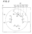
- Fig. 2 is a front view showing one example of a display image displayed on the image combining panel 9.
- the image combining panel 9 has a circular display area 15 in which an altimeter 16 is indicated on the left side thereof, a speed indicator 17 is indicated on the right side and an aircraft heading 18 is indicated at the lower part.
- a flight path image 22 which is an image of the target flight path to be followed is composed of a plurality of path marks 21a through 21e.
- the respective path marks 21a through 21e are indicated along the flight path at the positions where the aircraft should be positioned at a certain interval.
- the path marks 21 are indicated linearly on the whole such that the path mark at a long distance is represented shorter than the path mark at a short distance by utilizing the perspective representation. It allows the pilot to understand intuitively that which mark is the closest and which mark is the farthest among the plurality of path marks 21a through 21e.
- the own aircraft is represented by a W-shaped own-airframe symbol 19 and a velocity vector 20 is indicated approximately by a circle.
- the velocity vector 20 indicates the position where the aircraft is positioned at the next moment when it flies in the present state. Accordingly, it becomes possible to fly the own-aircraft symbol 19 along the respective path marks 21a through 21e and to fly the aircraft accurately along the target flight path by controlling so that the velocity vector 20 passes through the middle of the respective path marks 21.
- the own-aircraft symbol 19 is indicated horizontally as the reference without inclination.
- the respective path marks 21a through 21e are indicated with inclination corresponding to a difference between the target bank angle of the aircraft supposed when the aircraft is positioned at each path mark 21 and the current bank angle of the aircraft. Because the bank angle of the aircraft needs to be tilted to the right in Fig. 2, the respective path marks 21a through 21e are indicated while inclining to the right. Accordingly, it is possible to turn accurately along the respective path marks 21a through 21e by controlling so that the angle of inclination of the path mark 21a which is the closest mark where the own-aircraft symbol 19 first passes through coincides with the angle of inclination of the own-aircraft symbol 19.
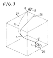
- Fig. 3 is a perspective view showing one example of a predetermined flight path 26 and an actual flight path 27 of the aircraft 12 in landing on a heli-spot 25. It is noted that the space in the vicinity of the heli-spot 25 is represented by a cube of imaginary lines for convenience to facilitate the understanding of the drawing.
- the predetermined target flight path 26 is indicated by a solid line and the actual flight path 27 of the aircraft 12 is indicated by an imaginary line in Fig. 3.
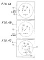
- Fig. 4A shows a display of the image combining panel 9 when the aircraft is positioned at the position a. Because the aircraft 12 is flying almost in parallel with the target flight path 26 on the right side of the target flight path 26 at the position a, the display position of the target flight path is gone outside of the display area 15 of the image combining panel 9 and the flight path image 22 is not displayed on the image combining panel 9.
- the computing means 4 calculates a position of the target flight path 26 with respect to the position of own aircraft from positional data of the aircraft 12 obtained from the aircraft flight data measuring means 3 and the target flight path data stored in the storage means 2 to display a target mark 28 pointing the direction of the target flight path from the center position of the display area 15 of the image combining panel 9.
- the target mark 28 of "+” may blink at the peripheral edge portion of the display area 15 where the target flight path 26 is positioned outside of the edge.
- the target mark 28 blinks at the left edge of the display area 15 of the image combining panel 9 as shown in Fig. 4A at the aircraft position a.
- the two dimensional position of the target flight path may be displayed as a position on the target flight path 26 closest to the aircraft 12 or may be displayed as a position on the target flight path slightly ahead of the closest position to the flight direction by taking into account the flight direction of the aircraft 12.
- the computing means 4 also calculates a distance between the position of the aircraft and the target flight path 26 to change the blinking interval of the target mark 28 corresponding to the distance. For instance, the blinking interval of the target mark 28 is shortened gradually as the aircraft 12 approaches to the target flight path 26 or the blinking interval of the target mark 28 is prolonged conversely as the aircraft leaves from the target flight path 26. It allows the pilot to understand easily whether the aircraft is approaching to or leaving from the target flight path 26 even under low visibility.
- Fig. 4B shows an image displayed on the image combining panel 9 when the aircraft 12 has reached to the position b from the position a along the flight path 27 indicated by the imaginary line.
- the blinking interval of the target mark 28 is shortened gradually because the aircraft 12 is approaching to the target flight path 26 as it flies from the position a to the position b as it is apparent from Fig. 3.
- the target flight path 26 is positioned at the lower left side at the position b, the target mark 28 blinks at the lower left edge of the display area 15 as shown in Fig. 4B.
- the aircraft 12 flies further and reaches to the position c in Fig. 3, the aircraft 12 flies close to the target flight path 26. Then, the flight path image 22 is displayed on the image combining panel 9 as shown in Fig. 4C. When the flight path image 22 enters the display area 15, the target mark 28 is erased. A T-shaped target heli-spot mark 29 is indicated in the flight path image 22 as shown in Fig. 4C. The pilot visually perceives this heli-spot mark 29 superimposed on the actual heli-spot 25. The aircraft 12 is guided to the actual heli-spot 25 safely by using this heli-spot mark 29 even under low visibility and the pilot has only to control the aircraft along the flight path image 22.
- the pilot When the aircraft 12 approaches near to the heli-spot 25 so that the pilot can see the heli-spot 25 easily, the pilot lands the helicopter on the heli-spot 25 visually by contact flight without using to the flight path image 22. Because there is a case when the helicopter lands vertically on the heli-spot 25, differing from fixed wing aircrafts, the target flight path lies right under the aircraft 12 during touch down and the flight path image 22 is not displayed on the image combining panel 9.
- the computing means 4 calculates the distance between the position of the aircraft 12 and the heli-spot 25 and erases the image displayed on the image combining panel 9 when this distance becomes shorter than a predetermined distance.
- the position at this time is the position d in Fig. 3 for example. It is also possible to control so as to erase the image displayed on the image combining panel 9 when a distance to the ground surface becomes shorter than a predetermined visible altitude h, not judging by the distance between the aircraft 12 and the heli-spot 25.
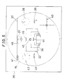
- Fig. 5 is a front view showing an image combining panel 35 provided in a flight path display apparatus according to another embodiment of the present invention. It is noted that the components corresponding to those in the image combining panel 9 shown in Fig. 2 are denoted by the same reference numerals and the structure other than the image combining panel 35 is the same as that of flight path display apparatus 1.
- a horizontal line 37 is indicated straightly across the display area 15 and a barometric altimeter 38, a vertical speed indicator 39 and a course deviation 40 are indicated on the right side of the display area 15.
- the course deviation 40 indicates deviations from the target flight path in the horizontal and vertical directions.
- An azimuth angle of the aircraft heading 41, an airspeed indicator 42 and a torque meter 43 are indicated on the left side of the display area 15.
- a bank angle indicator 46, the velocity vector 20, the own-aircraft symbol 19 and a slip ball 45 are indicated in this order from the top at the center of the display area 15.
- the flight path image 22 displayed on the image combining panel 35 as described above is composed of a plurality of path marks 36 provided at intervals along the flight path similarly to those displayed on the image combining panel 9.
- Each path mark 36 is composed of a pair of " [ " shaped marks facing to each other symmetrically.
- Such path marks 36 are indicated such that the farther from the aircraft, the smaller the size thereof becomes by utilizing the perspective representation to make the pilot to understand the flight path intuitively.
- a heli-spot mark 44 in which a straight line indicative of an approach direction is appended to the square heli-spot is shown at the center of the display area 15 in Fig. 5.
- Fig. 6 is a front view showing an image combining panel 50 provided in a flight path display apparatus of another embodiment of the present invention. It is noted that the apparatus has the same structure with the flight path display apparatus 1 except of the image combining panel 50. Among those indicated on the image combining panel 50, the display contents corresponding to those indicated on the image combining panels 9 and 35 will be denoted by the same reference numerals and an explanation thereof will be omitted here.
- a turn mark 53 indicative of a turn is indicated at the lower part of the display area 15 of the image combining panel 50 when the flight path is turning.
- the turn mark 53 is composed of an arrow 55 and an angle indication 52.
- the arrow 55 indicates the turning direction whether it is right or left and the angle indication 52 indicates an azimuth angle of the turning direction by numerals.
- the azimuth angle of the angle indication 52 is 270° in Fig. 6, so that it indicates that the flight path turns to the azimuth angle of 270° .
- the arrow 55 also makes the pilot to understand instantly that the flight path turns to right. Accordingly, even if the flight path turns largely and a turn ending position is gone outside of the display area 15, the turn mark 53 shows the pilot to understand clearly how much he should make the turn, thus improving the controllability.
- Such turn mark 53 may be indicated not only in the case when the flight path turns to right or left but also in the case when the flight path ascends or descends by indicating the vertical ascending/descending direction by the arrow 55 and by indicating a target value of ascending/descending rate numerically instead of the angle indication 52.
- the angle of turn 52 may be arranged so as to indicate the remaining angle of turn to the turn ending position by calculating the turn ending position and the current aircraft position by the computing means 4 when the airframe is turning.
- the arrow 55 may be indicated so that the length thereof is shortened corresponding to the remaining angle of turn.
- the flight path image 22 displayed on the image combining panel 50 is composed of a plurality of rectangular path marks 51 as shown in Fig. 6 and the pilot is required to control so that the own-aircraft symbol 19 passes through the center of each path mark 51.
- the path mark 51 of the near side is indicated large and the far side path mark 51 is indicated small by utilizing the perspective representation.
- each path mark 51 inclines corresponding to the bank angle of the aircraft supposed when the aircraft is positioned at each position.
- the path marks 51 may be indicated inclined to right or left corresponding not only to the bank angle of the aircraft but also to the attitude of the aircraft supposed when the aircraft is positioned on the path mark 51 by utilizing the perspective representation.
- a right edge 51a of the path mark 51 at the near side is indicated to be longer than a left edge 51b.
- an upper edge 51d of the near side path mark 51 is indicated to be longer than a lower edge 51c at the far side.
- Such rectangular path mark 51 allows the attitude of the aircraft at that position to be indicated, thus improving the controllability further.
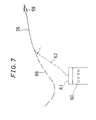
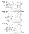
- Fig. 7 is a diagram showing a flight path when a helicopter 59 is going to land on a rooftop heliport 61 and Figs. 8A through 8C are front views showing display modes of the image combining panel 9 of the flight path display apparatus 1 at this time.
- the helicopter 59 is a twin-engined helicopter and is landing on the rooftop heliport 61 of a building 60 for example.
- the helicopter 59 flies to the point near the critical decision point L along the flight path 26.
- the helicopter 59 abort to land on the rooftop heliport 61 and flies toward an alternate heliport having a wider landing area by taking a new flight path 66.
- the helicopter 59 When the helicopter 59 has descended to the altitude lower than the critical decision point L, the helicopter 59 must land on the rooftop heliport 61 through a landing path 62. At this time, the landing path 62 becomes steep close to vertical and the pilot may be required to visually perceive the rooftop heliport 61 through a lower windshield glass at his feet in the normal helicopter 59.
- Figs. 8A through 8C show example indication of the flight path on the image combining panel 9 which is effective also in such circumstance.
- Fig. 8A shows the case when the helicopter 59 is right above the critical decision point L and is facing to the rooftop heliport 61.
- the own-aircraft symbol 19 the velocity vector 20 and a heli-spot mark 29 are lined up vertically at the center of the image combining panel 9, and the heli-spot mark 29 which is positioned outside of the display area 15 is indicated as the blinking mark.
- the altitude indicated by the altimeter 16 is not the altitude from the ground surface but is replaced by relative altitude from the critical decision point L to a symbol 61a of the rooftop heliport.
- a landing/take-off indication 65 for indicating the relative positional relationship between the aircraft position of the helicopter 59 and the rooftop heliport 61 is shown at the left side of the altimeter 16 by a symbol 64 of the helicopter, a symbol 60a of the building, the symbol 61a of the rooftop heliport and a symbol 62a of the target landing path.
- the respective symbols 64, 60a and 61a of the landing/take-off indication 65 are started to be indicated when the helicopter 59 has reached the critical decision point L.
- the target landing path 62a indicates the landing path from the critical decision point L to the rooftop heliport 61 by a broken line from a point of view of seeing it from the side thereof.
- the helicopter symbol 64 indicates the position of the aircraft with respect to the landing path 62a by a small circle.
- the building symbol 60a and the rooftop heliport symbol 61a are shown by a square and a letter H. They allow the pilot to readily understand the relative positional relationship between the rooftop heliport 61 and the position of the aircraft.
- Fig. 8B shows a state in which the helicopter 59 is descending at the altitude slightly below the critical decision point L and at the position deviating slightly to the right with respect to the rooftop heliport 61.
- a landing path symbol 63 of the actual aircraft is indicated by a solid line and the helicopter symbol 64 is shown at the lowermost end thereof in the landing/take-off indication 65.
- Fig. 8C shows a display mode in displaying also the path marks 21 when the aircraft is positioned at the same position with that in Fig. 8B.
- the indication of the path marks 21 indicates the deviation from the flight path in the right/left direction of the helicopter 59 which has deviated to the right side with respect to the rooftop heliport 61 to be readily corrected by the pilot.
- the display of the aircraft heading 18 is erased selectively so that the path marks 21 do not overlap with the display of other aircraft flight data.
- helicopter has been exemplified as the type of the aircraft, the effect of the present invention may be fully exerted also when the aircraft is a fixed wing aircraft or a VTOL aircraft (vertical take-off and landing aircraft) such as a tilt rotor aircraft.
- VTOL aircraft vertical take-off and landing aircraft
Landscapes
- Physics & Mathematics (AREA)
- Engineering & Computer Science (AREA)
- Radar, Positioning & Navigation (AREA)
- Remote Sensing (AREA)
- General Physics & Mathematics (AREA)
- Aviation & Aerospace Engineering (AREA)
- Optics & Photonics (AREA)
- Navigation (AREA)
- Traffic Control Systems (AREA)
Applications Claiming Priority (2)
| Application Number | Priority Date | Filing Date | Title |
|---|---|---|---|
| JP10076243A JP2939234B1 (ja) | 1998-03-24 | 1998-03-24 | 飛行経路表示装置 |
| JP7624398 | 1998-03-24 |
Publications (2)
| Publication Number | Publication Date |
|---|---|
| EP0945708A2 true EP0945708A2 (fr) | 1999-09-29 |
| EP0945708A3 EP0945708A3 (fr) | 1999-11-03 |
Family
ID=13599751
Family Applications (1)
| Application Number | Title | Priority Date | Filing Date |
|---|---|---|---|
| EP99200397A Withdrawn EP0945708A3 (fr) | 1998-03-24 | 1999-02-10 | Instrument indiquant la trajectoire de vol |
Country Status (3)
| Country | Link |
|---|---|
| US (1) | US6272404B1 (fr) |
| EP (1) | EP0945708A3 (fr) |
| JP (1) | JP2939234B1 (fr) |
Cited By (7)
| Publication number | Priority date | Publication date | Assignee | Title |
|---|---|---|---|---|
| FR2871610A1 (fr) * | 2004-06-15 | 2005-12-16 | Thales Sa | Procede de generation de symboles graphiques dynamiques sur un ecran matriciel |
| DE10022820B4 (de) * | 2000-05-10 | 2007-06-28 | Eads Deutschland Gmbh | Flugführungsanzeige |
| FR2916541A1 (fr) * | 2007-05-25 | 2008-11-28 | Thales Sa | Dispositif de visualisation tete haute pour aeronef comprenant des moyens d'affichage d'une symbologie dediee a l'evitement d'obstacles. |
| WO2012003512A3 (fr) * | 2010-07-02 | 2012-04-19 | Sandel Avionics, Inc. | Système et procédé de vol stationnaire d'aéronef |
| GB2512459A (en) * | 2013-02-06 | 2014-10-01 | Airbus Operations Sas | A method of assisting the piloting of an aircraft adapted for displaying symbols |
| CN109032166A (zh) * | 2018-03-08 | 2018-12-18 | 李绪臣 | 基于无人机即时跟踪行驶车辆的方法 |
| FR3134176A1 (fr) * | 2021-03-12 | 2023-10-06 | Airbus Helicopters | Aéronef et procédé d’aide au pilotage pour atterrir en conditions de visibilité dégradée |
Families Citing this family (21)
| Publication number | Priority date | Publication date | Assignee | Title |
|---|---|---|---|---|
| JP4609695B2 (ja) * | 2003-10-21 | 2011-01-12 | 日本精機株式会社 | 車両用表示装置 |
| FR2866960B1 (fr) * | 2004-02-27 | 2006-09-15 | Thales Sa | Dispositif optoelectronique securise d'aide au roulage pour aeronef |
| FR2875916B1 (fr) * | 2004-09-28 | 2015-06-26 | Eurocopter France | Procede et dispositif d'aide au pilotage d'un aeronef a voilure tournante au voisinage d'un point de pose ou de decollage |
| US7418318B2 (en) * | 2005-04-25 | 2008-08-26 | Honeywell International Inc. | Method and HUD system for displaying unusual attitude |
| US20070035563A1 (en) * | 2005-08-12 | 2007-02-15 | The Board Of Trustees Of Michigan State University | Augmented reality spatial interaction and navigational system |
| FR2897840B1 (fr) * | 2006-02-27 | 2009-02-13 | Eurocopter France | Procede et dispositif de traitement et de visualisation d'informations de pilotage d'un aeronef |
| US8035547B1 (en) | 2008-03-17 | 2011-10-11 | Garmin Switzerland Gmbh | System and method of assisted aerial navigation |
| DE102008023040B4 (de) * | 2008-05-09 | 2011-04-28 | Eurocopter Deutschland Gmbh | Flugführungsanzeige für einen Hubschrauber |
| WO2010014804A2 (fr) * | 2008-07-30 | 2010-02-04 | L-3 Communications Avionics Systems, Inc. | Écrans de vol évolués pour approches de précision et de non-précision |
| JP5916283B2 (ja) * | 2010-07-01 | 2016-05-11 | 三菱重工業株式会社 | 表示装置、操縦支援システム、及び表示方法 |
| US7982959B1 (en) | 2010-08-02 | 2011-07-19 | Matvey Lvovskiy | Head-up display |
| EP2558817B1 (fr) | 2010-09-30 | 2019-05-15 | Empire Technology Development LLC | Commande automatique de vol pour la modélisation des solides basée sur un avion sans pilote |
| US8774985B2 (en) * | 2011-07-22 | 2014-07-08 | The Boeing Company | Systems and methods for generating a command trajectory |
| JP6475411B2 (ja) * | 2014-01-08 | 2019-02-27 | 株式会社Subaru | 操縦支援装置及び操縦支援プログラム |
| US9523580B2 (en) | 2014-12-02 | 2016-12-20 | Honeywell International Inc. | System and method for aiding a pilot in locating an out of view landing site |
| WO2017004660A1 (fr) * | 2015-07-07 | 2017-01-12 | Crane Russell | Dispositif de réorientation de vol de pilote |
| FR3052553B1 (fr) * | 2016-06-13 | 2020-11-27 | Airbus Operations Sas | Systeme et procede d'affichage d'un aeronef |
| CN110086473A (zh) * | 2018-11-02 | 2019-08-02 | 深圳市科信南方信息技术有限公司 | 一种飞行数据修正方法、数据处理系统和存储介质 |
| JP2021091276A (ja) * | 2019-12-09 | 2021-06-17 | 株式会社島津製作所 | 移動体用操縦支援方法及び移動体用操縦支援システム |
| US11681301B2 (en) | 2021-06-29 | 2023-06-20 | Beta Air, Llc | System for a guidance interface for a vertical take-off and landing aircraft |
| KR102393844B1 (ko) * | 2021-09-06 | 2022-05-03 | 한화시스템 주식회사 | 항공기에서 수직 이착륙을 유도하는 시스템 및 방법 |
Family Cites Families (15)
| Publication number | Priority date | Publication date | Assignee | Title |
|---|---|---|---|---|
| FR2487505A1 (fr) | 1980-07-23 | 1982-01-29 | Dassault Avions | Dispositif d'assistance au pilotage d'un vehicule aerien |
| US5003305A (en) * | 1988-10-24 | 1991-03-26 | The Boeing Company | Apparatus and method for displaying aircraft flight path angle on an attitude display indicator |
| US4999780A (en) * | 1989-03-03 | 1991-03-12 | The Boeing Company | Automatic reconfiguration of electronic landing display |
| FR2666428B1 (fr) * | 1990-09-05 | 1994-09-23 | Aerospatiale | Procede de visualisation sur un ecran a bord d'un avion, de symboles d'aide au pilotage. |
| CA2060406C (fr) | 1991-04-22 | 1998-12-01 | Bruce Edward Hamilton | Systeme d'affichage d'images virtuelles a contours structurels |
| US5272652A (en) * | 1991-11-01 | 1993-12-21 | Eidetics International | Expanded field of view (EFOV) display for real-time, manned, interactive air combat simulation, including close-in combat |
| FR2694392B1 (fr) * | 1992-07-31 | 1994-10-07 | Sextant Avionique | Procédé d'assistance à la navigation. |
| JP2687304B2 (ja) | 1992-09-04 | 1997-12-08 | 科学技術庁航空宇宙技術研究所長 | ヘッドアップディスプレイを用いた計器着陸装置 |
| DE4314811A1 (de) * | 1993-05-05 | 1994-12-08 | Vdo Luftfahrtgeraete Werk Gmbh | Verfahren zur Darstellung von Flugführungsinformationen |
| JP2923509B2 (ja) | 1994-08-24 | 1999-07-26 | 科学技術庁長官官房会計課長 | 航空機の着陸支援方法及び装置 |
| FR2725803B1 (fr) | 1994-10-18 | 1997-01-03 | Sextant Avionique | Dispositif optoelectronique d'assistance au pilotage d'un aeronef |
| FR2733061B1 (fr) | 1995-04-13 | 1997-05-23 | Sextant Avionique | Dispositif optoelectronique d'aide au pilotage d'un aeronef par mauvaise visibilite |
| GB9508659D0 (en) * | 1995-04-28 | 1995-06-14 | Smiths Industries Plc | Aircraft instruments |
| US5745863A (en) * | 1995-09-22 | 1998-04-28 | Honeywell Inc. | Three dimensional lateral displacement display symbology which is conformal to the earth |
| JPH0991600A (ja) | 1995-09-26 | 1997-04-04 | Honda Motor Co Ltd | 航空機用ナビゲーション装置 |
-
1998
- 1998-03-24 JP JP10076243A patent/JP2939234B1/ja not_active Expired - Fee Related
-
1999
- 1999-02-10 EP EP99200397A patent/EP0945708A3/fr not_active Withdrawn
- 1999-02-16 US US09/250,281 patent/US6272404B1/en not_active Expired - Fee Related
Cited By (12)
| Publication number | Priority date | Publication date | Assignee | Title |
|---|---|---|---|---|
| DE10022820B4 (de) * | 2000-05-10 | 2007-06-28 | Eads Deutschland Gmbh | Flugführungsanzeige |
| FR2871610A1 (fr) * | 2004-06-15 | 2005-12-16 | Thales Sa | Procede de generation de symboles graphiques dynamiques sur un ecran matriciel |
| FR2916541A1 (fr) * | 2007-05-25 | 2008-11-28 | Thales Sa | Dispositif de visualisation tete haute pour aeronef comprenant des moyens d'affichage d'une symbologie dediee a l'evitement d'obstacles. |
| WO2008145590A3 (fr) * | 2007-05-25 | 2009-05-07 | Thales Sa | Dispositif de visualisation tête haute pour aéronef comprenant des moyens d'affichage d'une symbologie dédiée a l'évitement d'obstacles |
| WO2012003512A3 (fr) * | 2010-07-02 | 2012-04-19 | Sandel Avionics, Inc. | Système et procédé de vol stationnaire d'aéronef |
| CN103108806A (zh) * | 2010-07-02 | 2013-05-15 | 山德尔埃维翁尼克斯有限公司 | 飞机悬停系统和方法 |
| US8527117B2 (en) | 2010-07-02 | 2013-09-03 | Sandel Avionics, Inc. | Aircraft hover system and method |
| US8825235B2 (en) | 2010-07-02 | 2014-09-02 | Sandel Avionics, Inc. | Aircraft hover system and method |
| GB2512459A (en) * | 2013-02-06 | 2014-10-01 | Airbus Operations Sas | A method of assisting the piloting of an aircraft adapted for displaying symbols |
| GB2512459B (en) * | 2013-02-06 | 2020-04-01 | Airbus Operations Sas | A method, computer program and system for assisting piloting an aircraft by adapting the display of symbols |
| CN109032166A (zh) * | 2018-03-08 | 2018-12-18 | 李绪臣 | 基于无人机即时跟踪行驶车辆的方法 |
| FR3134176A1 (fr) * | 2021-03-12 | 2023-10-06 | Airbus Helicopters | Aéronef et procédé d’aide au pilotage pour atterrir en conditions de visibilité dégradée |
Also Published As
| Publication number | Publication date |
|---|---|
| US6272404B1 (en) | 2001-08-07 |
| JP2939234B1 (ja) | 1999-08-25 |
| EP0945708A3 (fr) | 1999-11-03 |
| JPH11268696A (ja) | 1999-10-05 |
Similar Documents
| Publication | Publication Date | Title |
|---|---|---|
| US6272404B1 (en) | Flight path indicated apparatus | |
| EP2107340B1 (fr) | Système d'affichage de points de cheminement | |
| EP2148175B1 (fr) | Systèmes d'affichage d'aéronef et procédés d'affichage amélioré des informations d'atterrissage | |
| RU2173660C2 (ru) | Трехмерный дисплей бокового отклонения | |
| EP2899509B1 (fr) | Procédé et appareil d'affichage des informations d'itinéraire de vol dans un giravion | |
| US7010398B2 (en) | Control system providing perspective flight guidance | |
| US11535394B2 (en) | Aircraft landing assistance method and memory storage device including instructions for performing an aircraft landing assistance method | |
| EP2101155B1 (fr) | Procédé et appareil pour afficher des informations d'itinéraire de vol dans un giravion | |
| EP2148176B1 (fr) | Systèmes d'affichage d'avion avec enveloppe d'avertissement d'obstacle | |
| US6255965B1 (en) | Device for aiding the piloting of an aircraft, especially a rotary-wing aircraft and in particular a helicopter | |
| EP2180457A1 (fr) | Procédé et appareil pour afficher des caractéristiques réalistes priorisées de photos sur un système de vision synthétique | |
| EP2154484B1 (fr) | Procédé et système pour l'utilisation d'un dispositif d'affichage à bord d'un avion | |
| EP1462767B1 (fr) | Système et procédé de guidage d'avions fournissant un guidage de vol en perspective | |
| US11056018B2 (en) | System and method for adjusting the correlation between a perspective of an onboard visual display and a current orientation of an inflight aircraft | |
| US11345484B2 (en) | Display system of an aircraft, able to display a localization marking of a zone of location of an approach light ramp and related method | |
| US5675328A (en) | Optoelectronic device for assistance in the piloting of an aircraft under conditions of poor visibility | |
| CA1331812C (fr) | Systeme symbolique d'affichage monte dans le casque du pilote et representant l'attitude de l'aeronef | |
| US5675327A (en) | Optoelectronic device for assistance in the piloting of an aircraft | |
| RU49297U1 (ru) | Информационно-управляющий комплекс летательных аппаратов | |
| US7365705B2 (en) | Flight control display | |
| RU44842U1 (ru) | Информационная командно-лидерная система | |
| Anderson | The Look-point Aircraft Coordinate Estimator (LACE) and potential applications |
Legal Events
| Date | Code | Title | Description |
|---|---|---|---|
| PUAI | Public reference made under article 153(3) epc to a published international application that has entered the european phase |
Free format text: ORIGINAL CODE: 0009012 |
|
| PUAL | Search report despatched |
Free format text: ORIGINAL CODE: 0009013 |
|
| AK | Designated contracting states |
Kind code of ref document: A2 Designated state(s): DE FR GB IT |
|
| AX | Request for extension of the european patent |
Free format text: AL;LT;LV;MK;RO;SI |
|
| AK | Designated contracting states |
Kind code of ref document: A3 Designated state(s): AT BE CH CY DE DK ES FI FR GB GR IE IT LI LU MC NL PT SE |
|
| AX | Request for extension of the european patent |
Free format text: AL;LT;LV;MK;RO;SI |
|
| 17P | Request for examination filed |
Effective date: 19991217 |
|
| AKX | Designation fees paid |
Free format text: DE FR GB IT |
|
| STAA | Information on the status of an ep patent application or granted ep patent |
Free format text: STATUS: THE APPLICATION HAS BEEN WITHDRAWN |
|
| 18W | Application withdrawn |
Withdrawal date: 20020702 |