EP0945630B1 - Kolbenstangenloser Linearantrieb - Google Patents
Kolbenstangenloser Linearantrieb Download PDFInfo
- Publication number
- EP0945630B1 EP0945630B1 EP99105323A EP99105323A EP0945630B1 EP 0945630 B1 EP0945630 B1 EP 0945630B1 EP 99105323 A EP99105323 A EP 99105323A EP 99105323 A EP99105323 A EP 99105323A EP 0945630 B1 EP0945630 B1 EP 0945630B1
- Authority
- EP
- European Patent Office
- Prior art keywords
- detection means
- linear drive
- housing
- drive according
- conductor
- Prior art date
- Legal status (The legal status is an assumption and is not a legal conclusion. Google has not performed a legal analysis and makes no representation as to the accuracy of the status listed.)
- Expired - Lifetime
Links
- 238000001514 detection method Methods 0.000 claims description 149
- 239000004020 conductor Substances 0.000 claims description 81
- 238000011156 evaluation Methods 0.000 claims description 63
- 238000007789 sealing Methods 0.000 claims description 62
- 230000005291 magnetic effect Effects 0.000 claims description 42
- 230000004044 response Effects 0.000 claims description 24
- 230000001419 dependent effect Effects 0.000 claims description 16
- 230000005540 biological transmission Effects 0.000 claims description 3
- 230000003014 reinforcing effect Effects 0.000 claims description 2
- 230000001960 triggered effect Effects 0.000 claims description 2
- 238000005259 measurement Methods 0.000 description 36
- 239000012530 fluid Substances 0.000 description 11
- 238000004519 manufacturing process Methods 0.000 description 11
- 230000004048 modification Effects 0.000 description 5
- 238000012986 modification Methods 0.000 description 5
- 238000013461 design Methods 0.000 description 3
- 230000001902 propagating effect Effects 0.000 description 3
- 230000002787 reinforcement Effects 0.000 description 3
- 230000015572 biosynthetic process Effects 0.000 description 2
- 239000003990 capacitor Substances 0.000 description 2
- 230000005284 excitation Effects 0.000 description 2
- 230000004907 flux Effects 0.000 description 2
- 239000002184 metal Substances 0.000 description 2
- 230000000149 penetrating effect Effects 0.000 description 2
- 230000007480 spreading Effects 0.000 description 2
- 230000009471 action Effects 0.000 description 1
- 230000006978 adaptation Effects 0.000 description 1
- 230000002238 attenuated effect Effects 0.000 description 1
- 230000008901 benefit Effects 0.000 description 1
- 230000008859 change Effects 0.000 description 1
- 238000011109 contamination Methods 0.000 description 1
- 238000010586 diagram Methods 0.000 description 1
- 230000000694 effects Effects 0.000 description 1
- 238000001125 extrusion Methods 0.000 description 1
- 230000005294 ferromagnetic effect Effects 0.000 description 1
- 230000003993 interaction Effects 0.000 description 1
- 230000001788 irregular Effects 0.000 description 1
- 238000002955 isolation Methods 0.000 description 1
- 238000000034 method Methods 0.000 description 1
- 230000036651 mood Effects 0.000 description 1
- 229920006395 saturated elastomer Polymers 0.000 description 1
- 239000003566 sealing material Substances 0.000 description 1
- 239000007787 solid Substances 0.000 description 1
Images


Classifications
-
- F—MECHANICAL ENGINEERING; LIGHTING; HEATING; WEAPONS; BLASTING
- F15—FLUID-PRESSURE ACTUATORS; HYDRAULICS OR PNEUMATICS IN GENERAL
- F15B—SYSTEMS ACTING BY MEANS OF FLUIDS IN GENERAL; FLUID-PRESSURE ACTUATORS, e.g. SERVOMOTORS; DETAILS OF FLUID-PRESSURE SYSTEMS, NOT OTHERWISE PROVIDED FOR
- F15B15/00—Fluid-actuated devices for displacing a member from one position to another; Gearing associated therewith
- F15B15/20—Other details, e.g. assembly with regulating devices
- F15B15/28—Means for indicating the position, e.g. end of stroke
- F15B15/2815—Position sensing, i.e. means for continuous measurement of position, e.g. LVDT
- F15B15/2869—Position sensing, i.e. means for continuous measurement of position, e.g. LVDT using electromagnetic radiation, e.g. radar or microwaves
-
- F—MECHANICAL ENGINEERING; LIGHTING; HEATING; WEAPONS; BLASTING
- F15—FLUID-PRESSURE ACTUATORS; HYDRAULICS OR PNEUMATICS IN GENERAL
- F15B—SYSTEMS ACTING BY MEANS OF FLUIDS IN GENERAL; FLUID-PRESSURE ACTUATORS, e.g. SERVOMOTORS; DETAILS OF FLUID-PRESSURE SYSTEMS, NOT OTHERWISE PROVIDED FOR
- F15B15/00—Fluid-actuated devices for displacing a member from one position to another; Gearing associated therewith
- F15B15/08—Characterised by the construction of the motor unit
- F15B15/082—Characterised by the construction of the motor unit the motor being of the slotted cylinder type
-
- F—MECHANICAL ENGINEERING; LIGHTING; HEATING; WEAPONS; BLASTING
- F15—FLUID-PRESSURE ACTUATORS; HYDRAULICS OR PNEUMATICS IN GENERAL
- F15B—SYSTEMS ACTING BY MEANS OF FLUIDS IN GENERAL; FLUID-PRESSURE ACTUATORS, e.g. SERVOMOTORS; DETAILS OF FLUID-PRESSURE SYSTEMS, NOT OTHERWISE PROVIDED FOR
- F15B15/00—Fluid-actuated devices for displacing a member from one position to another; Gearing associated therewith
- F15B15/20—Other details, e.g. assembly with regulating devices
- F15B15/28—Means for indicating the position, e.g. end of stroke
- F15B15/2815—Position sensing, i.e. means for continuous measurement of position, e.g. LVDT
- F15B15/2861—Position sensing, i.e. means for continuous measurement of position, e.g. LVDT using magnetic means
Definitions
- the invention relates to a rodless linear drive, with a housing delimiting a housing interior, the one longitudinal slot opening into the interior of the housing has, with a drive part, one in the housing interior longitudinally arranged drive section and one driver portion projecting outward through the longitudinal slot has, the longitudinal slot at least on the Drive part on both sides in the longitudinal direction adjacent sections by means of one from the interior of the housing Slot flanks adjacent sealing tape is closed, and with a position determining device for determining the Relative position of drive part and housing, on the housing or first detection means provided on the drive part and working with them on the other component provided provided second detection means and the one evaluation unit assigned to the first and / or second detection means contains.
- Such a rodless linear drive goes from DE-GM 29 508 517.
- the housing-side detection means are there from two on the two slot flanks of the longitudinal slot arranged resistance strips formed. A with the two resistance strips in contact, on the Carrier section arranged sliding contact provides the drive part Detection means.
- the evaluation unit is connected to the resistance measuring strips from one side, so they're depending on the position the contact point changing resistance of the two shorted Detect sections of the resistance measuring strips and from this the relative position of the driven part and the housing can determine.
- the sealing tape Spaced from the longitudinal slot in the interior of the housing.
- the drive part side Arrange the detection means in such a way that it corresponds to that of Longitudinal slot spaced section of the sealing tape work together the assembly of the drive part-side detection means due to the sufficiently available Space is simplified.
- the housing-side detection means can already in the manufacture of the sealing tape be provided on this. For example, it is possible the housing-side detection means during extrusion of the sealing tape in this, similar to the procedure for the production of sheathed cables or wires. at attaching the sealing tape to the housing of the rodless Linear drives become the housing side at the same time Detection means mounted, which makes the working and Time required to manufacture the linear drive is reduced.
- the evaluation unit can only be used with the first or second detection means. In this case the other means of registration do not require a connection point to the evaluation unit, so that it has a have a simple structure and therefore with little effort can be produced.
- the first Detection means for the relative movement of the housing and Drive part for example, in the field of cause second magnetic field changing magnetic field, wherein the second detection means is magnetic field dependent Generate detection signal that of the evaluation unit is fed to determine the relative position.
- This structure of the position determining device ensures a reliable function at low manufacturing costs.
- This may be the first means of registration several electrically conductive and / or magnetizable or permanent magnetic detection elements that act in the direction of the relative movement of the drive part and Housing, for example, regularly spaced apart are arranged.
- First detection means designed in this way are particularly easy to manufacture.
- the second Detection means contain a coil arrangement. This can be used as a magnetic field dependent sensor. It is possible that in the area of the coil arrangement existing magnetic field from the coil arrangement itself is caused. This way the first Detection means itself no magnetic field in the area Generate coil assembly, so that for their manufacture cheaper, non-permanent magnetic and in particular electrically conductive material can be used can.
- the relative position is via such a measurement signal can also be determined if the starting position of Housing and drive part unknown before the relative movement are. This means that none known to the evaluation unit Starting position must be defined to the relative position to be able to determine.
- a particularly simple position determination can take place if the relative position over time between sending out the measurement signal and arrival of one of the Measurement signal and the second detection means triggered Signal response is determined on the evaluation unit.
- the first detection means on Sealing tape may be provided and one in the longitudinal direction of the sealing tape extending conductor arrangement included. This enables simple transmission of the measurement signal or the signal response.
- the second detection means on the drive part 1 be provided and a discontinuity in the Induce conductor arrangement, the measurement signal at the Discontinuity a returning to the evaluation unit Triggers signal response.
- the discontinuity thus defines the relative position of the drive part and Casing.
- the signal response can in particular be from a Reflection of the measurement signal at the point of discontinuity be educated.
- a reflection can be of the second Detection means caused in a particularly simple manner become.
- the second detection means expediently contain a magnetic device whose magnetic field the conductor arrangement acts and the discontinuity causes.
- the conductor arrangement at least one externally accessible electrical Head has.
- the second Detection means one in contact with the electrical conductor have standing conductor tap, the contact point between conductor tap and electrical conductor Represents discontinuity.
- the conductor tap can at the contact point in a particularly simple manner a change in resistance of the conductor, from the incoming Seen measurement signal ago, achieved what a reflection at the point of discontinuity.
- the conductor tap is designed as a shorting bar, so to speak.
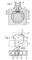
- a rodless linear drive 1 is shown, which delimits a housing interior 2 Housing 3 has.
- the housing 3 contains one extending in the longitudinal direction 4, tubular Housing body 5, which at its two end regions 6, 7 by means of a housing cover 8, 9 is closed.
- On the housing body 5 is a wall at a circumferential point radially penetrating longitudinal slot 12 provided, which opens into the housing interior 2 and in the longitudinal direction, for example, over the entire Length of the housing body 5 extends.
- a drive part 13 is provided on the housing 3 so as to be longitudinally movable, one in the housing interior 2 longitudinally movable arranged drive section 14 and one through the longitudinal slot 12 driver portion 15 projecting outwards having.
- the drive section thus provides the force-absorbing, driven part of the drive part 13, on which the driver section 15 is provided. This serves for example, objects not shown such as grippers, tools, workpieces or sensors wear that by means of the linear drive 1 in a desired Position should be brought.
- FIG. 1 acts it is a fluid-operated, especially pneumatic Linear drive 1, the drive section 14 of a piston 18 is formed.
- the rodless linear drive 1 to be electrically driven, for example, the drive section 14 via a longitudinal spindle, a Toothed or V-belts or the like can be moved.
- the housing interior 2 has an approximately circular cylindrical cross section.
- the piston 18 is in the Housing interior 2 arranged longitudinally movable. He has an elongated, tubular piston body 22, which at its two longitudinal end regions 23, 24 of each have a substantially cylindrical piston end piece 25, 26 is closed. Inside the piston body 22 is thus between the two piston end pieces 25, 26 Piston interior 27 limited.
- the piston 18 lies in the region of the piston end pieces 25, 26 sealing on the inner wall facing the housing interior 2 30 of the housing body 5.
- the Pistons on the two piston end pieces 25, 26 each a circumferential sealing arrangement 31, 32, which according to the example is formed by a sealing ring.
- the piston 18 in the housing interior 2 of the housing 3 is additionally on each piston end piece 25, 26 Guide ring 33, 34 provided.
- the two fluid chambers 37, 38 are in the region of the longitudinal slot 12 closed by means of a sealing tape 43, that from the inside on the flanks 44, 45 of the longitudinal sections extending along the fluid chambers 37, 38 46, 47 of the longitudinal slot 12 abuts.
- the sealing tape 43 is preferably seen in cross section trapezoidal, the two opposite, sloping side surfaces 48, 49 of the sealing tape on likewise inclined, radially towards each other Slit flanks of the longitudinal slot 12 lie flat.
- the sealing tape 43 is in the area with its two ends the housing cover 8, 9 fixed to the housing 3. Between these two fastening points 54, 55 is the sealing tape 43 stretched in its direction. Since it is usually made of elastic sealing material, are to increase the tensile strength according to FIG. 2 in the embodiment two in the sealing tape 43 continuously in the direction of extension of the sealing tape 43 extending reinforcing strands 56, 57 arranged. These can be made of a solid plastic be made or consist of metal. It understands yourself that in a modification to the embodiment too only one or more than two reinforcement strands could be provided, which are also on the outside of the sealing tape 43 could be arranged.
- actuated linear drive fulfills the sealing tape 43 no sealing function, but it protects it from contamination, that could penetrate into the housing 3.
- the linear drive 1 has a Position determining device 58, which is dash-dotted in FIG. 1 is indicated. about the specification and registration the relative position of drive part 13 and housing 3 can the position of the provided on the driver section 15, object to be positioned as required become.
- the position determination device 58 first provided according to the example on the sealing tape 43 Acquisition means 59 and cooperating with them, second detection means provided here on the drive part 13 60 on.
- the first detection means 59 therefore in the following as the housing side and the second detection means 60 as the drive part side Means of detection.
- Both the housing side and the drive part side Detection means 59, 60 are only in FIG. 1 shown schematically in dash-dotted lines.
- the drive part side Detection means 60 are preferably on the Drive part 14 or in the connection area 52 between Drive section 14 and driver section 15 arranged.
- the housing-side detection means 59 extend along the sealing tape 43 substantially above it whole length.
- the drive part-side detection means 60 work with them depending on the current relative position between drive part 13 and Housing 3 assigned point of the housing side Detection means 59 together, which as detection point 61 be designated. This detection point 61 is located in the embodiment on the section of the housing side Detection means 59 or the sealing tape 43, the runs inside the feed-through opening 53.
- the feed-through opening 53 can face the piston interior 27 be open, as shown in Fig. 1. This gives there is a lot of space for arranging the drive part side Detection means 60 in the area of the assignment office 61. Also the assembly of the drive part Detection means 60 can thus be carried out without problems become.
- An evaluation unit is provided with the housing-side detection means 59 64 of the position determining device 58 connected, the signals from the assigned housing-side Detection means 59 receive or signals to them Can send means of registration. By evaluating this The evaluation unit 61 can signal the current relative position between the drive part 13 and the housing 3 determine.
- the evaluation unit only with the drive part Detection means 60 connected.
- This connection is, for example, by means of electrical connecting conductors 66 realized.
- the housing-side detection means 59 and the drive part-side detection means 60 work contactlessly together so that during the relative movement the drive part 13 and the housing 3 no additional Friction or no additional wear occurs.
- the basic principle of the operation of the position determining device 58 is based on the fact that the housing-side detection means 59 during the relative movement of housing 3 and drive part 13 or Sealing tape 43 and drive part 13 are in the area of magnetic field on the drive part-side detection means 60 cause, the drive part side detection means 60 a magnetic field dependent detection signal generate that the evaluation unit 64 for determining the Relative position is supplied.
- the drive part-side detection means 60 at least one magnetic field-dependent sensor 67, which in the embodiment 3 is formed by a coil 68. This coil is connected to a voltage via the evaluation unit 64 applied so that it produces the magnetic field itself.
- the housing-side detection means 59 are in the sealing tape spaced apart along its direction arranged, magnetizable and / or electrically conductive detection elements 69 formed.
- the detection elements can, for example, of spaced individual metal balls can be formed. However, it is also possible, the individual detection elements connect with each other, thereby introducing the Detection elements 69 in the sealing tape 43 during manufacture is much easier. For example the detection elements 69 to a chain or band-like Structure.
- the external form of the In principle, detection elements 69 can be freely selected.
- the coil 68 surrounds the sealing tape 43 in the area of the detection point 61. With a relative movement of the drive part 13 and housing 3, the coil 68 moves along the Sealing tape 43, the magnetic flux in the Coil through the sensing elements moved through the coil 68 69 changes, which also changes to one changing voltage on the coil 68 leads from the evaluation unit 64 can be measured.
- the voltage signal on the coil 68 serves as a measure of the path that during the Relative movement between drive part 13 and housing 3 covered has been. Starting from a known, defined one The starting point can be the distance covered current relative position of drive part 1 13 and housing 3 can be determined in the evaluation unit 64.
- the detection elements 69 on the sealing tape 43 can simultaneously determine the distance traveled Distance also the direction of movement of the relative movement be determined.
- the detection elements 69 have irregular distances, so that during the Relative movement recorded by the evaluation unit 64 detection signal formed by the voltage on coil 68 certain, periodically recurring voltage profiles has, the voltage curves depending on the direction of movement are different.
- the periodically recurring, voltage curves containing the direction code, so to speak can also by in a section of the Sealing tape 43 caused different detection elements 69 be, the different detection elements 69 different voltage changes of the Cause coil voltage.
- Position determining device 58 have the drive part side Detection means 60 via only one Coil 68.
- these could also contain a coil arrangement, one with the evaluation unit 64 connected measuring coil is provided, the causes the detection signal. At least one more The coil of the coil arrangement could then be used as an excitation coil be formed that existing in the area of the measuring coil Magnetic field.
- the excitation coil so to speak and the measuring coil simultaneously from the single coil 68 educated.
- the coil 68 can also be part of an oscillating circuit 73 be, with a series resonant circuit realized, for example where the capacitor 74 and the ohmic Resistor 75 is provided in the evaluation unit 64, so that the connection to the coil 68 via the connecting conductor 66 takes place. It is understood that the capacitor 74 and the resistor 75 together with the coil 68 also on Drive part 13 could be arranged. If the ohmic Resistance of the coil 68 together with that of the connecting conductor 66 is already large enough, the separate Ohmic resistance 75 is also eliminated.
- the changing mood serves here of the resonant circuit 73 as a detection signal via which the Evaluation unit 64 the distance traveled and thus also the current relative position of drive part 13 and Housing 3 can determine.
- the Magnetic field-dependent sensor 67 of the drive part-side detection means 60 in the exemplary embodiment according to FIG. 4 for example from a magnetoresistive sensor or a Hall sensor, with another any magnetic field-dependent sensor can be used can.
- the existing in the area of the sensor 67 itself changing magnetic field is, for example, from the housing side Detection means 59 generated.
- detection means 59 is as in the previous embodiment spaced apart in the direction of extension of the Sealing tape 43 arranged detection elements 69, wherein this in the present case in the form of permanent magnets are executed.
- the sensing elements 69 are preferred connected together so that a kind of magnetic tape 78th arises.
- the magnetic tape 78 can already at Production of the sealing tape 43 introduced into this are or can also be arranged on the outside of the sealing tape 43.
- the connecting the individual detection elements 69 Longitudinal strands 79, 80 can simultaneously function as Reinforcement strands 56, 57 in the sealing tape 43 take over sufficient stability of the sealing tape 43 in its Ensure direction of extension seen.
- Each of the permanent magnetic detection elements 69 is generated a local magnetic field 81, which is schematic in FIG. 4 is indicated.
- sensor 67 moves along of the sealing tape 43, whereby it is replaced by the successive local magnetic fields 81 applied to the detection elements 69 becomes.
- the resultant in sensor 67 Detection signal is forwarded to the evaluation unit 64 and evaluated there to determine the relative position.
- a coding by the The detection elements 69 are arranged or configured, so that the distance covered from the detection signal Distance and the direction of movement of the relative movement let determine what determines the momentous relative position is possible.
- the first Detection means 59 can also be provided on the drive part 13, so that they are the drive part-side detection means form.
- the housing-side detection means are here formed by the second detection means 60.
- sealing strip 43 to provide a plurality of spaced apart magnetic field-dependent sensors 67, for example, several coils 68 that the represent second, housing-side detection means 60.
- the first detection means 59 on the drive part side could then be from a permanent magnetic or magnetizable and in the case of one formed by a coil 68 magnetic field dependent sensor 67 from an electrical conductive detection element 69 may be formed.
- Dependent on from the relative position of housing 3 and drive part 13 acts that arranged on the drive part 13 Detection element 69 mainly on the magnetic field or dependent Sensors 67 a at the assignment point 61 are present on the sealing tape 43. Because of the the assignment point 61 acting magnetic field Evaluation unit determine which of the magnetic field-dependent Sensors 67 is applied to the sealing tape 43, and thus the relative position of housing 3 and drive part 13 determine.
- the arrangement of the first and second detection means 59, 60 is therefore compared to the exemplary embodiments according to FIG 3 and 4, so to speak, reversed, with the now Magnetic field-dependent sensors on the sealing tape 43 and one or Several detection elements 59 are provided on the drive part 13 are.
- the advantage of this modification is that the current relative position of drive part 13 and Housing 3 does not have the last determined relative position and the relative movement that followed is determined, but arises directly from it, which of the magnetic field-dependent sensors 67 on the sealing tape 43 acted upon by the drive element-side detection element 59 becomes. The more sensors 67 provided on the sealing tape 43 and the closer they are to each other is selected, the more precise the relative position can be between drive part 13 and housing 3 can be determined.
- the evaluation unit 64 now only with the first detection means 59 connected, which in turn is the housing-side detection means represent. This eliminates the need to move the Connection conductor 66 with the drive part 13. Die Connection between the housing-side detection means 59 and the evaluation unit 64 is, for example, in Area of one of the attachment points 54, 55 between Sealing tape 43 and housing 3 are provided.
- connection is made as in the previous ones Embodiments via one or more electrical connecting conductors 66, alternatively also a connection with galvanic isolation could.
- the evaluation unit 64 and the housing-side detection means 59 inductively with one another be coupled.
- the basic principle of the design variants of the position determining device 58 is based on FIGS. 5 and 6 that the evaluation unit 64 a measurement signal via the transmits housing-side detection means 59 through Interaction between the housing side and the second, drive part-side detection means 59, 60 for Determination of the relative position is used.
- the signal form of the measurement signal can be arbitrary be, for example pulses, pulse trains or Waves, especially high-frequency waves, come into question.
- the relative position determined in the evaluation unit 64 in that the time between sending the measurement signal and arrival one of the measurement signal and the drive part Detection means 60 via the housing-side detection means 59 signal response returning to the evaluation unit 64 is determined.
- About the time span and the known transmission speed of measurement signal and Signal response can immediately be the relative position of Drive part 13 and housing 3 are determined.
- the evaluation unit 64 When determining the position by sending a measurement signal it is possible to find the relative position directly in the To determine evaluation unit 64.
- the evaluation unit 64 known, defined starting positions between drive part 13 and housing 3 need not be fixed because the current relative position does not exceed the distance traveled, but directly through the Evaluation of the measurement signal or the signal response takes place.
- the drive part side Detection means 60 cooperate in this way the conductor assembly 84 together that they in this at the Detection point 61 cause a discontinuity 85, on which the emitted by the evaluation unit 64 Measurement signal the signal response returning to the evaluation unit triggers.
- At least one of the conductors of conductor arrangement 84 can doing so to increase the tensile strength of the sealing tape 43 serving reinforcement strand 56, 57 form.
- the conductor arrangement 84 has in the exemplary embodiment 5 over at least one and preferably over two externally accessible electrical conductors 88, 89, see above that measurement signal and signal response in the form of electrical Signals are present.
- the electrical conductors 88, 89 are expediently on one of the outer surfaces of the sealing tape 43 provided that has no sealing function. According to the example, the electrical conductors 88, 89 are on the rear surface 90 facing housing interior 2 of the sealing tape 43 arranged.
- the discontinuity 85 is thereby in this embodiment caused that a conductor tap 91 of the drive part Detection means with the or electrical conductors 88, 89 is in contact, the Contact point of discontinuity 85 corresponds.
- a modification of the embodiment according to FIG. 5 could there is only one electrical conductor 88 or 89 be connected to the evaluation unit 64.
- the Conductor tap 91 of the drive part-side detection means 60 would then be designed such that he the resistance of the electrical conductor 88, 89 at the point of discontinuity 85 changed so that the incoming measurement signal reflects and may be broken.
- the reflection poses the signal response returning to the evaluation unit 64 As already described, you can then use the Time between sending the measurement signal and arrival the signal response the relative position between Drive part 13 and housing 3 are determined.
- the evaluation unit can 64 opposite end of the associated electrical Conductor 88, 89 by means of a corresponding Resistance to be adapted to reflect the reflection of the Discontinuity in the direction of propagation of the measurement signal continuous refractive signal at the end of the conductor avoid.
- the measurement signal is formed by an electrical pulse.
- the conductor tap 91 of the drive part-side detection means 60 is designed here as a shorting bar, the the two electrical conductors 88, 89 of the two-wire line electrically short-circuits at the point of discontinuity 85.
- the two-wire line forms a so-called "Lecher line", the measurement signal in particular is formed by a high frequency wave.
- the measurement signal is Measurement signal completely reflected at discontinuity 85, where the reflection forms the signal response, which is out of phase with the measurement signal by 180 °.
- a standing wire is thus formed in the second wire line Wave out.
- the Runtime measurement the relative position between the drive part 13 and housing 3 determined in the evaluation unit 64.
- drive part-side detection means 60 contactless the housing-side detection means 59.
- the conductor assembly 84 which, in contrast to the previous embodiments at least one contains magnetostrictive, electrically conductive conductor 96.
- the drive part-side detection means 60 comprise one Magnet device 94, which in the present case by a Permanent magnet is formed, the magnetic field on the magnetostrictive conductor 96 of the conductor arrangement 84 acts and causes the discontinuity 85.
- the magnetostrictive conductor 96 is, for example an amorphous or nanocrystalline, ferromagnetic conductor. By the influence of a Magnetic field, this is ferromagnetically saturated, causing a deformation (magnetostriction) of the magnetostrictive Conductor 96 is caused. This Deformation point forms the discontinuity 85 the measurement signal emitted by the evaluation unit 64 is reflected and broken.
- a first possibility is that the reflection forms the signal response. That is based on the Discontinuity 85 in the direction of propagation of the Measurement signal along the magnetostrictive conductor 96 on propagating refractive signal would be at the evaluation unit 64 reflected the opposite end one more time become. This could lead to errors in the calculation of the Lead relative position. That is why the magnetostrictive Conductor 96 on its opposite the evaluation unit 64 Terminated by means of a resistor 97 in such a way that the reflection factor is zero and therefore Adaptation exists.
- the second possibility for the formation of the signal response results itself through the amorphous or nanocrystalline formation of the magnetostrictive conductor 96.
- discontinuity 85 arises simultaneously in both Mechanical wave propagating directions, in particular Torsion.
- the one returning in the direction of the evaluation unit 64 mechanical wave provides the signal response represents and can therefore due to their known propagation speed via the runtime measurement for Determination of the relative position of housing 3 and drive part 13 serve.
- the distance from the discontinuity 85 together with the refractive signal to that of the evaluation unit opposite end of the conductor 96 spreading further mechanical shaft is preferably on this The end of the conductor is so attenuated that there is no significant reflection takes place to errors in determining the relative position to be avoided in the evaluation unit 64.
- the evaluation unit also leads with these design options 64 a transit time measurement of the measurement signal and Signal response through, from which they get the relative position determined between drive part 13 and housing 3.
- FIG. 6 is a further variant for the execution of the Position determining device 58 shown.
- the magnetostrictive conductor in the form of a tube-like one Sound wave guide 100 is formed, which in FIG. 6 is shown in broken lines.
- Coaxial within the Sound waveguide 100 is an electrical measuring conductor 101 arranged, via which the measurement signal starting from the evaluation unit 64 is transmitted.
- the discontinuity 85 triggers the incoming measurement signal via the Sound waveguide 100 returning to the evaluation unit 64 first and one opposed to this further propagating second mechanical wave, where it is in the present case a torsion shaft is.
- the first mechanical wave is the Signal response represents, and the second mechanical wave Damped at the end of the conductor to avoid reflections.
Landscapes
- Engineering & Computer Science (AREA)
- Physics & Mathematics (AREA)
- Fluid Mechanics (AREA)
- Mechanical Engineering (AREA)
- General Engineering & Computer Science (AREA)
- Health & Medical Sciences (AREA)
- Electromagnetism (AREA)
- Radar, Positioning & Navigation (AREA)
- Remote Sensing (AREA)
- Toxicology (AREA)
- Measurement Of Length, Angles, Or The Like Using Electric Or Magnetic Means (AREA)
- Actuator (AREA)
Description
- Fig. 1
- einen mit einer Positionsbestimmungseinrichtung ausgestatteten fluidbetätigten kolbenstangenlosen Linearantrieb im Längsschnitt,
- Fig. 2
- den Linearantrieb aus Fig. 1 in einem Querschnitt gemäß der Schnittlinie II-II,
- Fig. 3
- den prinzipiellen Aufbau eines ersten Ausführungsbeispiels einer Positionsbestimmungseinrichtung, wobei die antriebsteilseitigen Erfassungsmittel eine Spulenanordnung und die gehäuseseitigen Erfassungsmittel mehrere magnetisierbare Erfassungselemente aufweisen, in einer schematischen Darstellung,
- Fig. 4
- ein zweites Ausführungsbeispiel einer Positionsbestimmungseinrichtung in der Darstellung wie Fig. 3, wobei die antriebsteilseitigen Erfassungsmittel einen magnetfeldabhängigen Sensor und die gehäuseseitigen Erfassungsmittel mehrere permanentmagnetische Erfassungselemente aufweisen,
- Fig. 5
- ein drittes Ausführungsbeispiel einer Positionsbestimmungseinrichtung in der Darstellung wie Fig. 3, wobei die gehäuseseitigen Erfassungsmittel von außen zugängliche elektrische Leiter und die antriebsteilseitigen Erfassungsmittel einen Leiterabgriff aufweisen, und
- Fig. 6
- weitere Ausführungsformen der Positionsbestimmungseinrichtung in der Darstellung gemäß Fig. 3, wobei die gehäuseseitigen Erfassungsmittel einen magnetostriktiven Leiter und die antriebsteilseitigen Erfassungsmittel eine Magneteinrichtung aufweisen.
Claims (26)
- Kolbenstangenloser Linearantrieb, mit einem einen Gehäuse-Innenraum (2) begrenzenden Gehäuse (3), das einen in den Gehäuse-Innenraum (2) mündenden Längsschlitz (12) aufweist, mit einem Antriebsteil (13), das eine im Gehäuse-Innenraum (2) längsbewegbar angeordnete Antriebspartie (14) und eine durch den Längsschlitz (12) hindurch nach außen ragende Mitnehmerpartie (15) aufweist, wobei der Längsschlitz (12) zumindest an den dem Antriebsteil (13) beiderseits in Längsrichtung (4) benachbarten Längenabschnitten (46, 47) mittels eines vom Gehäuse-Innenraum (2) her an den Schlitzflanken (44, 45) anliegenden Dichtbandes (43) verschlossen ist, und mit einer Positionsbestimmungseinrichtung (58) zur Bestimmung der Relativposition von Antriebsteil (13) und Gehäuse (3), die am Gehäuse (3) oder am Antriebsteil (13) vorgesehene erste Erfassungsmittel (59) und mit diesen zusammenarbeitende, am jeweils anderen Bauteil (13 bzw. 3) vorgesehene zweite Erfassungsmittel (60) aufweist und die eine den ersten und/oder zweiten Erfassungsmitteln (59, 60) zugeordnete Auswerteeinheit (64) enthält, dadurch gekennzeichnet, daß die gehäuseseitigen Erfassungsmittel (59) an dem Dichtband (43) vorgesehen sind.
- Kolbenstangenloser Linearantrieb nach Anspruch 1, dadurch gekennzeichnet, daß das Dichtband (43) wenigstens einen in seiner Erstreckungsrichtung am oder im Dichtband (43) verlaufenden Verstärkungsstrang (56, 57) aufweist, der einen elektrischen Leiter der gehäuseseitigen Erfassungsmittel (59) bildet.
- Kolbenstangenloser Linearantrieb nach Anspruch 1 oder 2, dadurch gekennzeichnet, daß die ersten und die zweiten Erfassungsmittel (59, 60) kontaktlos zusammenarbeiten.
- Kolbenstangenloser Linearantrieb nach Anspruch 3, dadurch gekennzeichnet, daß die ersten Erfassungsmittel (59) bei der Relativbewegung von Gehäuse (3) und Antriebsteil (13) ein sich im Bereich der zweiten Erfassungsmittel (60) änderndes Magnetfeld hervorrufen, wobei die zweiten Erfassungsmittel (60) ein Magnetfeldabhängiges Erfassungssignal erzeugen, das der Auswerteeinheit (64) zur Bestimmung der Relativposition zugeführt wird.
- Kolbenstangenloser Linearantrieb nach Anspruch 4, dadurch gekennzeichnet, daß es sich bei den ersten Erfassungsmitteln (60) um mehrere elektrisch leitfähige und/oder magnetisierbare oder permanentmagnetische Erfassungselemente (69) handelt, die in Richtung der Relativbewegung von Antriebsteil (13) und Gehäuse (3) aufeinanderfolgend angeordnet sind.
- Kolbenstangenloser Linearantrieb nach einem der Ansprüche 3 bis 5, dadurch gekennzeichnet, daß die zweiten Erfassungsmittel (60) zumindest einen magnetfeldabhängigen Sensor (67) aufweisen.
- Kolbenstangenloser Linearantrieb nach einem der Ansprüche 3 bis 6, dadurch gekennzeichnet, daß die zweiten Erfassungsmittel (60) eine Spulenanordnung (68) enthalten.
- Kolbenstangenloser Linearantrieb nach Anspruch 7, dadurch gekennzeichnet, daß das im Bereich der Spulenanordnung (68) vorhandene Magnetfeld von der Spulenanordnung (68) selbst hervorgerufen ist.
- Kolbenstangenloser Linearantrieb nach Anspruch 7 oder 8, dadurch gekennzeichnet, daß die Spulenanordnung (68) wenigstens eine das Erfassungssignal hervorrufende Meßspule (68) enthält, die mit der Auswerteeinheit (64) verbunden ist.
- Kolbenstangenloser Linearantrieb nach Anspruch 9, dadurch gekennzeichnet, daß die Meßspule (68) Teil eines Schwingkreises (73) ist, wobei die Auswerteeinheit (64) die Relativposition insbesondere mittels der Verstimmung des Schwingkreises (73) bestimmt.
- Kolbenstangenloser Linearantrieb nach einem der Ansprüche 1 bis 10, dadurch gekennzeichnet, daß die Auswerteeinheit (64) über die ersten Erfassungsmittel (59) ein Meßsignal aussendet, das durch Zusammenwirken mit den zweiten Erfassungsmitteln (60) zur Ermittlung der Relativposition dient.
- Kolbenstangenloser Linearantrieb nach Anspruch 11, dadurch gekennzeichnet, daß die Relativposition über die Zeitspanne zwischen Aussenden des Meßsignals und Eintreffen einer vom Meßsignal und den zweiten Erfassungsmitteln (60) ausgelösten Signalantwort in der Auswerteeinheit (64) ermittelt wird.
- Kolbenstangenloser Linearantrieb nach Anspruch 11 oder 12, dadurch gekennzeichnet, daß die ersten Erfassungsmittel (59) am Dichtband (43) vorgesehen sind und eine sich in Längsrichtung des Dichtbandes (43) erstreckende Leiteranordnung (84) aufweisen.
- Kolbenstangenloser Linearantrieb nach Anspruch 13, dadurch gekennzeichnet, daß die zweiten Erfassungsmittel (60) am Antriebsteil (13) vorgesehen sind und in der Leiteranordnung (84) eine Unstetigkeitsstelle (85) hervorrufen, wobei das Meßsignal an der Unstetigkeitsstelle (85) eine zur Auswerteeinheit (64) zurücklaufende Signalantwort auslöst.
- Kolbenstangenloser Linearantrieb nach Anspruch 14, dadurch gekennzeichnet, daß die Signalantwort von einer Reflexion des Meßsignals an der Unstetigkeitsstelle (85) gebildet ist.
- Kolbenstangenloser Linearantrieb nach Anspruch 14 oder 15, dadurch gekennzeichnet, daß die zweiten Erfassungsmittel (60) eine Magneteinrichtung (94) enthalten, deren Magnetfeld auf die Leiteranordnung (84) einwirkt und die Unstetigkeitsstelle (85) hervorruft.
- Kolbenstangenloser Linearantrieb nach Anspruch 16, dadurch gekennzeichnet, daß wenigstens einer der Leiter (96 bzw. 100) der Leiteranordnung (84) magnetostriktive Eigenschaften aufweist.
- Kolbenstangenloser Linearantrieb nach Anspruch 17 dadurch gekennzeichnet, daß der magnetostriktive, insbesondere nanokristalline oder amorphe Leiter (96) elektrisch leitfähig ist, wobei das Meßsignal über diesen Leiter (96) übertragen wird und an der Unstetigkeitsstelle (85) eine auf diesem Leiter (96) zur Auswerteeinheit (64) zurücklaufende mechanische Welle hervorruft, die die Signalantwort darstellt.
- Kolbenstangenloser Linearantrieb nach Anspruch 17, dadurch gekennzeichnet, daß der magnetostriktive Leiter von einem rohrähnlichen Schallwellenleiter (100) gebildet ist, der koaxial zu einem zur Meßsignalübertragung dienenden elektrischen Meßleiter (101) angeordnet ist, wobei an der Unstetigkeitsstelle (85) durch das eintreffende Meßsignal eine zur Auswerteeinheit (64) zurücklaufende mechanische Welle hervorgerufen wird.
- Kolbenstangenloser Linearantrieb nach einem der Ansprüche 11 bis 19 dadurch gekennzeichnet, daß die am Dichtband (43) vorgesehene Leiteranordnung (84) mindestens einen von außen zugänglichen elektrischen Leiter (88, 89) aufweist und die zweiten Erfassungsmittel (60) einen mit diesem elektrischen Leiter (88, 89) in Kontakt stehenden Leiterabgriff (91) enthalten, wobei die Kontaktstelle zwischen Leiterabgriff (91) und elektrischem Leiter (88, 89) die Unstetigkeitsstelle (85) darstellt.
- Kolbenstangenloser Linearantrieb nach Anspruch 20, dadurch gekennzeichnet, daß der Leiterabgriff (91) mehrere elektrische Leiter (88, 89) der Leiteranordnung (84) an der Unstetigkeitsstelle (85) elektrisch verbindet.
- Kolbenstangenloser Linearantrieb nach einem der Ansprüche 1 bis 21, dadurch gekennzeichnet, daß die Auswerteeinheit (64) lediglich mit den ersten Erfassungsmitteln(59) oder den zweiten Erfassungsmitteln (60) verbunden ist.
- Kolbenstangenloser Linearantrieb nach einem der Ansprüche 1 bis 22, dadurch gekennzeichnet, daß die ersten Erfassungsmittel (59) am Dichtband (43) und die zweiten Erfassungsmittel (60) am Antriebsteil (13) vorgesehen sind.
- Kolbenstangenloser Linearantrieb nach einem der Ansprüche 1 bis 23, dadurch gekennzeichnet, daß die Auswerteeinheit (64) lediglich mit den gehäuseseitigen Erfassungsmitteln (59 bzw. 60) verbunden ist.
- Kolbenstangenloser Linearantrieb nach Anspruch 24, dadurch gekennzeichnet, daß die Verbindung zwischen den gehäuseseitigen Erfassungsmitteln (59) und der Auswerteeinheit (64) im Bereich einer Befestigungsstelle (54, 55) vorgesehen ist, an der das Dichtband (43) am Gehäuse (3) befestigt ist.
- Kolbenstangenloser Linearantrieb nach einem der Ansprüche 1 bis 25, dadurch gekennzeichnet, daß es sich um einen fluidbetätigten Linearantrieb (1) handelt, wobei die Antriebspartie (14) von einem Kolben (18) gebildet ist.
Applications Claiming Priority (2)
| Application Number | Priority Date | Filing Date | Title |
|---|---|---|---|
| DE19813371 | 1998-03-26 | ||
| DE19813371A DE19813371C2 (de) | 1998-03-26 | 1998-03-26 | Kolbenstangenloser Linearantrieb |
Publications (2)
| Publication Number | Publication Date |
|---|---|
| EP0945630A1 EP0945630A1 (de) | 1999-09-29 |
| EP0945630B1 true EP0945630B1 (de) | 2004-07-28 |
Family
ID=7862428
Family Applications (1)
| Application Number | Title | Priority Date | Filing Date |
|---|---|---|---|
| EP99105323A Expired - Lifetime EP0945630B1 (de) | 1998-03-26 | 1999-03-16 | Kolbenstangenloser Linearantrieb |
Country Status (3)
| Country | Link |
|---|---|
| EP (1) | EP0945630B1 (de) |
| JP (1) | JPH11311208A (de) |
| DE (2) | DE19813371C2 (de) |
Families Citing this family (1)
| Publication number | Priority date | Publication date | Assignee | Title |
|---|---|---|---|---|
| DE102007061386B4 (de) * | 2007-12-19 | 2021-07-08 | manroland sheetfed GmbH | Rotationsdruckmaschine mit Leichtbauelementen |
Family Cites Families (7)
| Publication number | Priority date | Publication date | Assignee | Title |
|---|---|---|---|---|
| DE3244616C2 (de) * | 1982-12-02 | 1986-06-19 | Dr. Johannes Heidenhain Gmbh, 8225 Traunreut | Vorrichtung zur Messung von Vorschubbewegungen |
| EP0492751A1 (de) * | 1990-12-20 | 1992-07-01 | MANNESMANN Aktiengesellschaft | Druckmittelbetriebener Arbeitszylinder mit profiliertem Zylinderrohr |
| DE9101734U1 (de) * | 1991-02-15 | 1991-05-23 | Hygrama Ag, Rotkreuz | Druckmittelzylinder |
| JPH04341603A (ja) * | 1991-05-17 | 1992-11-27 | S G:Kk | ロッドレスシリンダ装置 |
| DE4241189A1 (de) * | 1992-12-03 | 1994-06-09 | Mannesmann Ag | Einrichtung zur Positionsermittlung bei einem druckmittelbetriebenen Arbeitszylinder |
| DE29508517U1 (de) * | 1995-05-23 | 1995-08-10 | Festo Kg, 73734 Esslingen | Kolbenstangenloser Linearantrieb |
| DE29518539U1 (de) * | 1995-11-22 | 1996-01-18 | Festo Kg, 73734 Esslingen | Positionserfassungsvorrichtung |
-
1998
- 1998-03-26 DE DE19813371A patent/DE19813371C2/de not_active Expired - Fee Related
-
1999
- 1999-03-16 DE DE59910037T patent/DE59910037D1/de not_active Expired - Fee Related
- 1999-03-16 EP EP99105323A patent/EP0945630B1/de not_active Expired - Lifetime
- 1999-03-26 JP JP11084027A patent/JPH11311208A/ja active Pending
Also Published As
| Publication number | Publication date |
|---|---|
| JPH11311208A (ja) | 1999-11-09 |
| EP0945630A1 (de) | 1999-09-29 |
| DE19813371A1 (de) | 1999-10-07 |
| DE19813371C2 (de) | 2001-12-20 |
| DE59910037D1 (de) | 2004-09-02 |
Similar Documents
| Publication | Publication Date | Title |
|---|---|---|
| DE102010056271B4 (de) | Sensoranordnung zur Erfassung sowohl der Axial- als auch der Drehstellung einer in Längsrichtung verschieblichen und drehbaren Welle | |
| DE69015195T2 (de) | Telemetrische Sensor zur Detektion mechanischer Deformation eines Gegenstandes mittels Messung der Veränderungen von Magnetfeldstärke. | |
| DE2933557C2 (de) | Meßumformer zur berührungslosen Weg- oder Geschwindigkeitsmessung | |
| EP0218042B1 (de) | Magnetfeldabhängiger, elektronischer Annäherungsschalter | |
| EP1474651B1 (de) | Abstandsmessvorrichtung und verfahren zur bestimmung eines abstands | |
| EP2564164B1 (de) | Magnetisches längenmesssystem, längenmessverfahren sowie herstellungsverfahren eines magnetischen längenmesssystems | |
| EP2142810B1 (de) | Abstandsmessvorrichtung und verfahren zur bestimmung eines abstands und ein geeigneter reflexionskörper | |
| DE19738316A1 (de) | Berührungsloser Wegmesser insbesondere zur Verschleißmessung von Bremsklötzen | |
| EP1538424A1 (de) | Mikrowellenwegmesssystem für elektrodynamischen Direktantrieb | |
| EP0936444B1 (de) | Anordnung zur berührungslosen Positionsbestimmung eines Messobjektes, vorzugsweise einer Schaltwelle eines Kraftfahrzeuggetriebes | |
| DE102008061227A1 (de) | Abstandsmessvorrichtung und Verfahren zur Ermittlung eines Abstands in einer Leitungsstruktur | |
| DE3017202C2 (de) | Einrichtung zur Ermittlung der Drehzahl eines drehbaren oder der Frequenz eines linear schwingenden Bauteils aus magnetisch permeablem Material | |
| DE102010029870A1 (de) | Sensor | |
| EP0945630A1 (de) | Kolbenstangenloser Linearantrieb | |
| DE3902491A1 (de) | Vorrichtung zum feststellen mindestens einer mit der bewegung eines beweglichen koerpers verbundenen variablen | |
| EP0591614A1 (de) | Kolben-Zylinder-Aggregat | |
| DE29812227U1 (de) | Vorrichtung zum Erfassen von Schalterstellungen eines mechanisch betätigbaren Schalters | |
| WO2006058726A1 (de) | Abstandsmessvorrichtung und verfahren zur messung eines abstands | |
| EP1981156A2 (de) | Elektrische Linearantriebsvorrichtung | |
| DE10160904B4 (de) | Sensorsystem zur Erfassung der Position von beweglichen Hydraulikelementen | |
| EP2049804B1 (de) | Positionssensoreinrichtung und damit ausgestatteter aktor | |
| DE10250846B4 (de) | Positionssensoranordnung | |
| DE4335594A1 (de) | Drehwinkelsensor zur Ermittlung eines Drehwinkels | |
| DE10329044B4 (de) | Einrichtung zur Ermittlung der aktuellen Stellung eines Antriebsgliedes entlang des Hubwegs oder Drehwinkels, insbesondere bei einem druckmittelbetriebenen Linear- bzw. Drehantrieb | |
| DE4432827A1 (de) | Positionsbestimmungseinrichtung |
Legal Events
| Date | Code | Title | Description |
|---|---|---|---|
| PUAI | Public reference made under article 153(3) epc to a published international application that has entered the european phase |
Free format text: ORIGINAL CODE: 0009012 |
|
| AK | Designated contracting states |
Kind code of ref document: A1 Designated state(s): DE FR GB IT SE |
|
| AX | Request for extension of the european patent |
Free format text: AL;LT;LV;MK;RO;SI |
|
| 17P | Request for examination filed |
Effective date: 19990809 |
|
| AKX | Designation fees paid |
Free format text: DE FR GB IT SE |
|
| 17Q | First examination report despatched |
Effective date: 20030218 |
|
| GRAP | Despatch of communication of intention to grant a patent |
Free format text: ORIGINAL CODE: EPIDOSNIGR1 |
|
| GRAS | Grant fee paid |
Free format text: ORIGINAL CODE: EPIDOSNIGR3 |
|
| GRAA | (expected) grant |
Free format text: ORIGINAL CODE: 0009210 |
|
| AK | Designated contracting states |
Kind code of ref document: B1 Designated state(s): DE FR GB IT SE |
|
| REG | Reference to a national code |
Ref country code: GB Ref legal event code: FG4D Free format text: NOT ENGLISH |
|
| REG | Reference to a national code |
Ref country code: SE Ref legal event code: TRGR |
|
| REF | Corresponds to: |
Ref document number: 59910037 Country of ref document: DE Date of ref document: 20040902 Kind code of ref document: P |
|
| GBT | Gb: translation of ep patent filed (gb section 77(6)(a)/1977) |
Effective date: 20040915 |
|
| PLBE | No opposition filed within time limit |
Free format text: ORIGINAL CODE: 0009261 |
|
| STAA | Information on the status of an ep patent application or granted ep patent |
Free format text: STATUS: NO OPPOSITION FILED WITHIN TIME LIMIT |
|
| ET | Fr: translation filed | ||
| 26N | No opposition filed |
Effective date: 20050429 |
|
| PGFP | Annual fee paid to national office [announced via postgrant information from national office to epo] |
Ref country code: FR Payment date: 20060322 Year of fee payment: 8 |
|
| PGFP | Annual fee paid to national office [announced via postgrant information from national office to epo] |
Ref country code: IT Payment date: 20060331 Year of fee payment: 8 |
|
| PG25 | Lapsed in a contracting state [announced via postgrant information from national office to epo] |
Ref country code: SE Free format text: LAPSE BECAUSE OF NON-PAYMENT OF DUE FEES Effective date: 20070317 |
|
| EUG | Se: european patent has lapsed | ||
| GBPC | Gb: european patent ceased through non-payment of renewal fee |
Effective date: 20070316 |
|
| REG | Reference to a national code |
Ref country code: FR Ref legal event code: ST Effective date: 20071130 |
|
| PGFP | Annual fee paid to national office [announced via postgrant information from national office to epo] |
Ref country code: SE Payment date: 20060317 Year of fee payment: 8 |
|
| PG25 | Lapsed in a contracting state [announced via postgrant information from national office to epo] |
Ref country code: GB Free format text: LAPSE BECAUSE OF NON-PAYMENT OF DUE FEES Effective date: 20070316 |
|
| PG25 | Lapsed in a contracting state [announced via postgrant information from national office to epo] |
Ref country code: FR Free format text: LAPSE BECAUSE OF NON-PAYMENT OF DUE FEES Effective date: 20070402 |
|
| PGFP | Annual fee paid to national office [announced via postgrant information from national office to epo] |
Ref country code: DE Payment date: 20080313 Year of fee payment: 10 |
|
| PGFP | Annual fee paid to national office [announced via postgrant information from national office to epo] |
Ref country code: GB Payment date: 20060307 Year of fee payment: 8 |
|
| PG25 | Lapsed in a contracting state [announced via postgrant information from national office to epo] |
Ref country code: IT Free format text: LAPSE BECAUSE OF NON-PAYMENT OF DUE FEES Effective date: 20070316 |
|
| PG25 | Lapsed in a contracting state [announced via postgrant information from national office to epo] |
Ref country code: DE Free format text: LAPSE BECAUSE OF NON-PAYMENT OF DUE FEES Effective date: 20091001 |