EP0945595A2 - Gekühlte Gasturbinenschaufel - Google Patents
Gekühlte Gasturbinenschaufel Download PDFInfo
- Publication number
- EP0945595A2 EP0945595A2 EP99105483A EP99105483A EP0945595A2 EP 0945595 A2 EP0945595 A2 EP 0945595A2 EP 99105483 A EP99105483 A EP 99105483A EP 99105483 A EP99105483 A EP 99105483A EP 0945595 A2 EP0945595 A2 EP 0945595A2
- Authority
- EP
- European Patent Office
- Prior art keywords
- cooling passage
- blade
- cooling
- passage
- row
- Prior art date
- Legal status (The legal status is an assumption and is not a legal conclusion. Google has not performed a legal analysis and makes no representation as to the accuracy of the status listed.)
- Withdrawn
Links
- 238000001816 cooling Methods 0.000 claims abstract description 167
- 239000002826 coolant Substances 0.000 claims abstract description 44
- 230000002093 peripheral effect Effects 0.000 claims abstract description 22
- 238000011144 upstream manufacturing Methods 0.000 claims abstract description 13
- 238000004891 communication Methods 0.000 claims abstract description 7
- 238000005192 partition Methods 0.000 claims description 3
- 238000007789 sealing Methods 0.000 description 4
- 230000000694 effects Effects 0.000 description 3
- 230000002708 enhancing effect Effects 0.000 description 3
- 238000013459 approach Methods 0.000 description 2
- 238000010276 construction Methods 0.000 description 2
- 230000003014 reinforcing effect Effects 0.000 description 2
- 230000001133 acceleration Effects 0.000 description 1
- 238000004519 manufacturing process Methods 0.000 description 1
- 238000000034 method Methods 0.000 description 1
- 230000001105 regulatory effect Effects 0.000 description 1
Images


Classifications
-
- F—MECHANICAL ENGINEERING; LIGHTING; HEATING; WEAPONS; BLASTING
- F01—MACHINES OR ENGINES IN GENERAL; ENGINE PLANTS IN GENERAL; STEAM ENGINES
- F01D—NON-POSITIVE DISPLACEMENT MACHINES OR ENGINES, e.g. STEAM TURBINES
- F01D5/00—Blades; Blade-carrying members; Heating, heat-insulating, cooling or antivibration means on the blades or the members
- F01D5/12—Blades
- F01D5/14—Form or construction
- F01D5/18—Hollow blades, i.e. blades with cooling or heating channels or cavities; Heating, heat-insulating or cooling means on blades
- F01D5/187—Convection cooling
-
- F—MECHANICAL ENGINEERING; LIGHTING; HEATING; WEAPONS; BLASTING
- F05—INDEXING SCHEMES RELATING TO ENGINES OR PUMPS IN VARIOUS SUBCLASSES OF CLASSES F01-F04
- F05D—INDEXING SCHEME FOR ASPECTS RELATING TO NON-POSITIVE-DISPLACEMENT MACHINES OR ENGINES, GAS-TURBINES OR JET-PROPULSION PLANTS
- F05D2250/00—Geometry
- F05D2250/10—Two-dimensional
- F05D2250/18—Two-dimensional patterned
- F05D2250/185—Two-dimensional patterned serpentine-like
-
- F—MECHANICAL ENGINEERING; LIGHTING; HEATING; WEAPONS; BLASTING
- F05—INDEXING SCHEMES RELATING TO ENGINES OR PUMPS IN VARIOUS SUBCLASSES OF CLASSES F01-F04
- F05D—INDEXING SCHEME FOR ASPECTS RELATING TO NON-POSITIVE-DISPLACEMENT MACHINES OR ENGINES, GAS-TURBINES OR JET-PROPULSION PLANTS
- F05D2260/00—Function
- F05D2260/20—Heat transfer, e.g. cooling
- F05D2260/221—Improvement of heat transfer
- F05D2260/2212—Improvement of heat transfer by creating turbulence
Definitions
- the present invention relates generally to a gas turbine cooled blade and more specifically to a gas turbine cooled blade having a seal air supply passage for supplying therethrough a seal air from an outer peripheral side to an inner peripheral side of a stationary blade and a gas turbine cooled blade having a structure for enhancing a heat transfer rate in a cooling passage of a moving blade or a stationary blade.
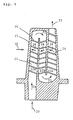
- Fig. 7 is a schematic cross sectional view of one example of a prior art gas turbine cooled blade, wherein Fig. 7(a) is a longitudinal cross sectional view and Fig. 7(b) is a cross sectional view taken on line III-III of Fig. 7(a).
- Fig. 8 is a schematic cross sectional view of another example of a prior art gas turbine cooled blade, wherein Fig. 8(a) is a longitudinal cross sectional view and Fig. 8(b) is a cross sectional view taken on line IV-IV of Fig. 8(a).
- number of stages is decided by the capacity of turbine, for example, in a gas turbine constructed in four stages, its second, third and fourth stage stationary blades, respectively, have moving blades disposed in front and back thereof and each of the stationary blades is structured to be surrounded by adjacent moving blades and rotor discs supporting them.
- a main flow high temperature gas does not flow into a gap of each portion in an interior of the stationary blade, said gap being formed there in process of manufacture, assembly, etc.
- such a construction is employed usually that a bleed air from compressor is flown into the interior of the stationary blade from its outer peripheral side to be supplied into a cavity portion on an inner peripheral side of the stationary blade as a seal air so that a pressure in the cavity portion is kept higher than that in a main flow high temperature gas path, thereby preventing inflow of the main flow high temperature gas.
- Fig. 7 is of a seal air supply structure using a seal tube 4 for leading therethrough a seal air wherein the seal tube 4 is provided in a stationary blade at a position apart from an inner surface of a blade portion 5 to pass through a first row cooling passage A of a leading edge portion in the blade portion 5, thereby a blade outer peripheral side communicates with a cavity portion of a blade inner peripheral side so that a seal air 3 is supplied into the cavity portion through the seal tube 4.
- Numeral 2 designates a cooling medium, which is supplied for cooling of the stationary blade to flow through the first row cooling passage A and further through a second row cooling passage B and a third row cooling passage C in the blade portion 5 and is discharged into the main flow high temperature gas from a blade trailing edge portion.
- FIG. 8 Another example in the prior art shown in Fig. 8 is constructed such that a sealing air 3 is supplied directly into a first row cooling passage A to be used both for a sealing air and a blade cooling air wherein such a seal tube as used in the example of Fig. 7 is not used and omitted.
- cooling passages so that cooling medium is led to pass therethrough for cooling of the interior of the blade.
- Fig. 9 is a longitudinal cross sectional view of the conventional gas turbine cooled blade.
- numeral 21 designates a cooled blade (moving blade), in which a cooling passage 22 is provided passing therethrough.
- Numeral 23 designates a cooling medium, which flows into the blade from a base portion of the cooled blade 21 to flow through cooling passages 22a, 22b and 22c sequentially and is discharged into a gas path where a high temperature gas 25 flows.
- Numeral 24 designates a rib and there are provided a plurality of ribs 24 being arranged inclinedly on inner walls of the cooling passages 22a, 22b, 22c, as described later, so that the cooling medium 23 flows in each of the cooling passages like arrow 29 with a heat transfer rate therein being enhanced.
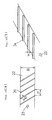
- Fig. 10 is an enlarged view of one of the cooling passages of the cooled blade 21 in the prior art as described above, wherein Fig. 10(a) is a plan view thereof and Fig. 10(b) is a perspective view thereof.
- the plurality of ribs 24 are provided, each extending in an entire width W of the cooling passage 22 to be disposed inclinedly with a constant angle ⁇ relative to a flow direction of the cooling medium 23 with a rib to rib pitch P and projecting in a height e.
- the cooling medium 23 is led into the cooling passage 22 from outside of the cooled blade 21 to flow through the cooled blade 21 for sequential cooling therein and is discharged into the high temperature gas 25, as described in Fig. 9.
- the rib 24 causes turbulences in the flow of the cooling medium 23 so that the heat transfer rate of the cooling medium 23 flowing through the cooling passage 22 is enhanced.
- Fig. 11 is a schematic explanatory view of a flow pattern and a cooling function thereof of the cooling medium 23 flowing in the cooling passage 22 of Fig. 10, wherein Fig. 11(a) shows a flow direction of the cooling medium 23 seen on a plan view of the cooling passage 22, Fig. 11(b) shows a flow of the cooling medium 23 seen from one side of Fig. 11(a), Fig. 11(c) shows the flow of the cooling medium 23 seen perspectively and Fig. 11(d) shows a heat transfer rate distribution in the cooling passage 22.
- the cooling medium 23 becomes a swirl flow 23a as in Fig. 11(a) to flow toward downstream from upstream there so as to move in a constant direction along the rib 24 provided inclinedly as in Fig. 11(c).
- Fig. 11(d) there is generated a high heat transfer rate area 30 on an upstream side thereof where the swirl flow 23a approaches to a wall surface of the cooling passage 22 (boundary layer there is thin).
- the cooling medium flows to generate the swirl flow 23a which flows along the rib 24 in the cooling passage 22 as shown in Fig. 11(a) and there are formed the high heat transfer rate area 30 in the place where the swirl flows 23a approaches to the wall surface of the cooling passage 22 and the area of lower heat transfer rate in the place where the swirl flow 23a leaves from the wall surface of the cooling passage 22 as shown in Fig. 11(d), hence the heat transfer rate becomes non-uniform to cause a lowering of the average heat transfer rate.
- the present invention first provides a gas turbine cooled blade having therein a plurality of cooling passages extending in a turbine radial direction, a portion of said plurality of cooling passages being used as a seal air supply passage as well for supplying therethrough a seal air into a cavity on a blade inner peripheral side from a blade outer peripheral side, characterized in that a cooling passage of first row from upstream is covered both at its blade inner peripheral side and blade outer peripheral side and communicates with a cooling passage of second row from same via a communication hole bored in a partition wall between itself and said cooling passage of second row as well as communicates with a main flow gas path via a film cooling hole bored in a blade wall passing therethrough to a blade outer surface; and said cooling passage of second row communicates with the cavity on the blade inner peripheral side so as to form the seal air supply passage.
- the seal air supplied from the blade outer peripheral side flows through the selected second row cooling passage where there are less thermal load and less heat exchange rate of the seal air, thereby an appropriate temperature as the seal air can be maintained.
- a portion of the seal air in the second row cooling passage is separated to flow into the first row cooling passage via the communication hole to be used as a cooling air.
- This cooling air first cools the blade leading edge portion which surrounds the first row cooling passage and then makes film cooling of the blade outer surface, passing through the film cooling hole.
- the present invention provides also a gas turbine cooled blade mentioned above, characterized in that said seal air supply passage is formed not by the second row cooling passage but being selected from a third and subsequent row cooling passages downstream of the second row cooling passage.
- the cooling passage of the seal air supplied from the blade outer peripheral side to the blade inner peripheral side is formed being selected from the cooling passages of downstream of the second row cooling passage, thereby the heat exchange rate in the blade portion corresponding to that cooling passage is small sufficiently so that the temperature of the seal air can be maintained to a further lower level and the seal air which is more suitable to be led into the blade inner peripheral side cavity can be obtained.
- the present invention further provides a gas turbine cooled blade having therein a cooling passage, said cooling passage having on its inner wall a plurality of ribs disposed so as to cross a cooling medium flow direction with a predetermined rib to rib pitch, characterized in that each of said plurality of ribs extends from a side end of said cooling passage to a position beyond a central portion thereof to be disposed alternately right and left against the cooling medium flow direction and inclinedly in mutually opposing directions as well as to make contact at its one end beyond the central portion of said cooling passage with a side face of another rib of immediately upstream thereof.
- each of the ribs is disposed alternately against the cooling medium flow direction and inclinedly in mutually opposing directions while making contact with the side face of the immediate upstream rib at the position slightly biased toward the side from the central portion of the cooling passage.
- each of said plurality of ribs has a shape in which a height thereof reduces gradually from a higher portion at its said one end beyond the central portion of said cooling passage toward a lower portion at its the other end at the side end of said cooling passage.
- each of the ribs has a shape of height which reduces gradually from its one higher end to the other lower end and the higher end makes contact with the side face of the immediate upstream rib, thereby there are generated the small swirl flows along the cooling medium flow at the contact position of the two ribs, which results in assisting to enhance the heat transfer rate further, in addition to the enhancement of the average heat transfer rate by the above-mentioned invention.
- the present invention further provides a gas turbine cooled blade having therein a cooling passage, said cooling passage having on its inner wall a plurality of ribs disposed so as to cross a cooling medium flow direction with a predetermined rib to rib pitch, characterized in that there is provided a pin projecting substantially perpendicularly at a predetermined position in a longitudinal direction of a rib of all or a portion of said plurality of ribs.
- the present invention by the swirl flows generated by the ribs crossing the cooling medium flow, there are formed the high heat transfer rate areas and in addition thereto, the pins are provided projectingly so that swirl flows are further generated on the downstream side of the respective pins to flow along the inclinedly disposed ribs, thereby the high heat transfer rate areas are formed also in the area where the high heat transfer rate area had been hardly formed in the prior art, which results in forming of an increased and uniform high heat transfer rate area in the entire cooling passage and enhancement of the average heat transfer rate.
- the present invention provides a gas turbine cooled blade as mentioned above, characterized in that said pin is provided in plural pieces with a predetermined pin to pin pitch on the rib.
- the pin is provided in plural pieces with the predetermined pitch between the pins on the rib on which the pin is to be provided, thereby the high heat transfer rate areas which are formed by the swirl flows generated by the pins can be further increased to form a more uniform high heat transfer rate area and the average heat transfer rate is further enhanced.
- the present invention further provides a gas turbine cooled blade as mentioned above, characterized in that said pin is provided in said cooling passage so as to connect a dorsal side portion and a ventral side portion of the blade.
- the pin is provided so as to connect the blade dorsal side and the blade ventral side, thereby the pin can be used as a reinforcing element in the cooling passage as well, in addition to the effect of the enhancement of the average heat transfer rate by the increased high heat transfer rate area.
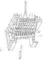
- a seal air 3 having function of blade cooling as well is not led into a first row cooling passage A provided in a blade leading edge portion but is led into a second row cooling passage B where there is less thermal load, and while the air cools the second row cooling passage B, a portion of the seal air 3 is separated to be supplied into the first row cooling passage A and remaining portion thereof is led into an inner cavity 10 as the seal air.
- a plurality of communication holes 6 in a cooling passage wall 11 which partitions the first row cooling passage A provided in the blade leading edge portion and the second row cooling passage B.
- an inner shroud 8 and an outer shroud 9 of the first row cooling passage A are structured to be closed in a turbine radial direction.
- third and subsequent row cooling passages are structured same as those in the prior art described above.
- a cooling medium 1 having both of sealing function and blade cooling function is supplied into the second row cooling passage B from an outer shroud 9 side and after having cooled inner surfaces of the passage, the cooling medium 1 is partially led into the inner cavity 10 as the seal air 3.
- Remaining part of the cooling medium 1 is supplied into the first row cooling passage A through the communication holes 6 and, after having cooled inner surfaces of the passage as a cooling air, is blown into a main flow high temperature gas through the film cooling holes 7 for effecting a film cooling of blade outer surfaces.
- a cooling medium 2 having passed through the third row cooling passage C enters the fourth row cooling passage D formed in a serpentine shape and the fifth row cooling passage E sequentially for cooling of blade inner surfaces and is then blown into the main flow high temperature gas from a blade trailing edge portion.
- the seal air is supplied into the second row cooling passage B where there is less thermal load and a portion of the cooling air is supplied into the first row cooling passage A through the communication holes 6 of the cooling passage wall 11 for effecting the film cooling of the blade outer surfaces, thereby the blade outer surfaces of the portion corresponding to the second row cooling passage B are applied to by the film cooling and reduced of temperature so that the thermal load of the second row cooling passage B is lowered further and temperature rise of the seal air in the second row cooling passage B is suppressed further securely. Also, because temperature rise of the seal air supplied into the inner cavity 10 via the second row cooling passage B is suppressed sufficiently, there is no need of using a seal tube, which results in no increase of parts number and working man-hour.
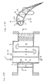
- a throttle may be provided at a cooling passage outlet on the inner cavity 10 side.
- seal air 3 is not limited to that supplied from the second row cooling passage B but may be supplied from the third row cooling passage C or subsequent ones selectively.
- the third row cooling passage C and subsequent cooling passages are in further less thermal load than the second row cooling passage B, thereby the seal air is maintained to a more preferable lower temperature so that the seal air which is suitable for the inner cavity 10 can be secured.
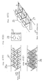
- Fig. 3 shows a main part of a cooling passage of a gas turbine cooled blade of the second embodiment, wherein Fig. 3(a) is a partially enlarged plan view thereof, Fig. 3(b) is a side view thereof and Fig. 3(c) is a perspective view thereof.
- Fig. 3(a) is a partially enlarged plan view thereof
- Fig. 3(b) is a side view thereof
- Fig. 3(c) is a perspective view thereof.
- numeral 31 designates a plurality of ribs, each of said ribs being disposed on an inner wall surface of a cooling passage 22 extending alternately toward both side directions of a main flow direction of a cooling medium 23 and being inclined with a constant angle ⁇ to said main flow direction of the cooling medium 23 and with a constant rib to rib pitch P in said main flow direction of the cooling medium 23.
- each of the ribs 31 is disposed inclinedly in a width Wa which is smaller than an entire width W of the cooling passage 22 to extend having such a height as gradually reduces from at its one higher end having a height e at a position of the width Wa which is slightly biased to a side end of the cooling passage 22 beyond a central portion thereof toward its the other lower end of downstream outer side thereof having a height f which is lower than e.
- Each of the ribs 31 makes contact at its end portion of the height e with an approximately central portion of a side face of another rib 31 disposed immediately upstream thereof so as to project higher than the side face of said another rib 31 at a position of the contact portion and there are disposed alternately a plurality of ribs 31 to extend inclinedly in mutually opposing directions with the rib to rib pitch P in the main flow direction of the cooling medium 23 in the cooling passage 22.
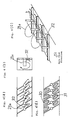
- Fig. 4 is a schematic explanatory view of a flow pattern and a heat transfer rate distribution of the cooling medium in the second embodiment of Fig. 3, wherein Fig. 4(a) is a plan view of the flow pattern, Fig. 4(b) is a side view thereof, Fig. 4(c) is a perspective view thereof and Fig. 4(d) is a view showing the heat transfer rate distribution.
- Fig. 4(a) is a plan view of the flow pattern
- Fig. 4(b) is a side view thereof
- Fig. 4(c) is a perspective view thereof
- Fig. 4(d) is a view showing the heat transfer rate distribution.
- the cooling medium flowing in the cooling passage 22 generates a swirl flow 23b which flows swirlingly and inclinedly downstream toward a side portion of the cooling passage 22 from the central portion thereof in the respective spaces formed with the pitch P between the ribs 31.
- the rib 31 has a shape which reduces its height from e to f and there occurs a difference in the height at the portion where the ribs 31 make contact with each other, there arises a small swirl flow 27 at a corner portion of the rib 31 having the height e.
- the contact portions of the ribs 31 are formed alternately on both side portions of the cooling passage 22, the small swirl flow 27 is also formed on both side portions of same.
- the rib 31 changes its shape to reduce the height from e to f, hence the small swirl flow 27 occurring at the corner portion of the rib 31 in the contact portion of the ribs 31 is also generated on both side portions of the cooling passage 22 to assist generation of the high heat transfer rate area 26, which results in further enhancing the heat transfer rate.
- the ribs 31 are disposed alternately and inclinedly in the mutually opposing directions wherein the end portion of the rib 31 makes contact with side surface of the upstream side rib 31 and the rib 31 has a shape to reduce its height from e to f, thereby the swirl flow 23b is generated and the high heat transfer rate area 26 is formed uniformly on both side portions of the cooling passage 22.
- the small swirl 27 is generated at the corner portion of the contact portion of the ribs 31 to assist generation of the high heat transfer rate area 26, which results in enhancing the average heat transfer rate of the entire cooled blade.
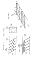
- Fig. 5 shows a gas turbine cooled blade of a third embodiment according to the present invention, wherein Fig. 5(a) is a partially enlarged plan view, Fig. 5(b) is a side view thereof and Fig. 5(c) is a perspective view thereof.
- the present third embodiment is made basically on a same shape of rib and same arrangement thereof as in the prior art, shown in Fig. 10, with an improvement being added to enhance a heat transfer rate in a low heat transfer rate area.
- the pin 28 has a shape of diameter d and height h, as shown in Fig. 5(b).
- the pin 24 on each of the ribs 24 but the pin 24 is not necessarily provided on each of the ribs 24 but may be provided on every two, three or more ribs 24.
- Fig. 6 is a schematic explanatory view of a flow pattern and a heat transfer rate distribution of the cooling medium in the third embodiment of Fig. 5, wherein Fig. 6(a) is a plan view of the flow pattern, Fig. 6(b) is a side view thereof, Fig. 6(c) is a perspective view and Fig. 6(d) is a view showing the heat transfer rate distribution.
- the swirl flow 23b is generated by the rib 24 and the high heat transfer rate area 30 is thereby formed, as shown in Figs. 6(a) and (d).
- This high heat transfer rate area 30 has a same function as that of the prior art shown in Fig. 11.
- the pin 28 may be provided in plural pieces along a longitudinal direction of the rib 24 and in this case, the high heat transfer rate area can be enlarged.
- the pin 28 is provided projectingly, it will be preferable if the pin 28 is provided so as to connect a dorsal side portion and a ventral side portion of the blade, because the pin 28 may function in this case not only for acceleration of cooling but also as a reinforcing element of the blade which is a hollow blade having a thin wall structure.
- the high heat transfer rate area is enlarged, thereby the average heat transfer rate can be enhanced.
Landscapes
- Engineering & Computer Science (AREA)
- Mechanical Engineering (AREA)
- General Engineering & Computer Science (AREA)
- Turbine Rotor Nozzle Sealing (AREA)
Applications Claiming Priority (4)
| Application Number | Priority Date | Filing Date | Title |
|---|---|---|---|
| JP7918198 | 1998-03-26 | ||
| JP07918198A JP3801344B2 (ja) | 1998-03-26 | 1998-03-26 | ガスタービン冷却静翼 |
| JP7918498 | 1998-03-26 | ||
| JP07918498A JP3426956B2 (ja) | 1998-03-26 | 1998-03-26 | ガスタービン冷却翼 |
Publications (2)
| Publication Number | Publication Date |
|---|---|
| EP0945595A2 true EP0945595A2 (de) | 1999-09-29 |
| EP0945595A3 EP0945595A3 (de) | 2001-10-10 |
Family
ID=26420234
Family Applications (1)
| Application Number | Title | Priority Date | Filing Date |
|---|---|---|---|
| EP99105483A Withdrawn EP0945595A3 (de) | 1998-03-26 | 1999-03-17 | Gekühlte Gasturbinenschaufel |
Country Status (3)
| Country | Link |
|---|---|
| US (1) | US6290462B1 (de) |
| EP (1) | EP0945595A3 (de) |
| CA (3) | CA2266140C (de) |
Cited By (10)
| Publication number | Priority date | Publication date | Assignee | Title |
|---|---|---|---|---|
| EP1091091A2 (de) * | 1999-10-05 | 2001-04-11 | United Technologies Corporation | Methode und Einrichtung zur Kühlung einer Wand in einer Gasturbine |
| EP1707741A2 (de) * | 2005-04-01 | 2006-10-04 | General Electric Company | Konvektions- und Film-Kühlung der Hinterkante einer Turbinenleitschaufel |
| EP1921268A1 (de) * | 2006-11-08 | 2008-05-14 | Siemens Aktiengesellschaft | Turbinenschaufel |
| EP2284363A1 (de) * | 2009-07-07 | 2011-02-16 | Rolls-Royce plc | Hitzetransfer-Passage |
| EP2886797A1 (de) * | 2013-12-20 | 2015-06-24 | Alstom Technology Ltd | Ein hohle gekühlte Rotor- oder Leitschaufel einer Gasturbine, wobei die kühlkanäle Stifte mit Verbindungsstreben beinhalten |
| WO2015184294A1 (en) * | 2014-05-29 | 2015-12-03 | General Electric Company | Fastback turbulator |
| EP3034791A1 (de) * | 2014-12-15 | 2016-06-22 | United Technologies Corporation | Wärmeübertragungssockel mit strömungsführungsmerkmalen |
| WO2018186891A1 (en) * | 2017-04-07 | 2018-10-11 | General Electric Company | Cooling assembly for a turbine assembly |
| FR3094032A1 (fr) * | 2019-03-22 | 2020-09-25 | Safran Aircraft Engines | Aube de turbomachine d’aeronef et son procede de fabrication par moulage a cire perdue |
| RU2800747C2 (ru) * | 2019-03-22 | 2023-07-27 | Сафран Эркрафт Энджинз | Лопатка авиационного газотурбинного двигателя и способ ее изготовления посредством литья по выплавляемым восковым моделям |
Families Citing this family (41)
| Publication number | Priority date | Publication date | Assignee | Title |
|---|---|---|---|---|
| GB2345942B (en) * | 1998-12-24 | 2002-08-07 | Rolls Royce Plc | Gas turbine engine internal air system |
| US6902372B2 (en) * | 2003-09-04 | 2005-06-07 | Siemens Westinghouse Power Corporation | Cooling system for a turbine blade |
| US7163373B2 (en) * | 2005-02-02 | 2007-01-16 | Siemens Power Generation, Inc. | Vortex dissipation device for a cooling system within a turbine blade of a turbine engine |
| US7837440B2 (en) * | 2005-06-16 | 2010-11-23 | General Electric Company | Turbine bucket tip cap |
| US7513745B2 (en) * | 2006-03-24 | 2009-04-07 | United Technologies Corporation | Advanced turbulator arrangements for microcircuits |
| US7637720B1 (en) | 2006-11-16 | 2009-12-29 | Florida Turbine Technologies, Inc. | Turbulator for a turbine airfoil cooling passage |
| US7857588B2 (en) * | 2007-07-06 | 2010-12-28 | United Technologies Corporation | Reinforced airfoils |
| DE602007011256D1 (de) * | 2007-08-08 | 2011-01-27 | Alstom Technology Ltd | Gasturbinenschaufel mit interner Kühlung |
| WO2009028067A1 (ja) * | 2007-08-30 | 2009-03-05 | Mitsubishi Heavy Industries, Ltd. | ガスタービンの翼冷却構造 |
| US8517684B2 (en) * | 2008-03-14 | 2013-08-27 | Florida Turbine Technologies, Inc. | Turbine blade with multiple impingement cooled passages |
| US8192146B2 (en) * | 2009-03-04 | 2012-06-05 | Siemens Energy, Inc. | Turbine blade dual channel cooling system |
| US8568085B2 (en) | 2010-07-19 | 2013-10-29 | Pratt & Whitney Canada Corp | High pressure turbine vane cooling hole distrubution |
| US8807945B2 (en) | 2011-06-22 | 2014-08-19 | United Technologies Corporation | Cooling system for turbine airfoil including ice-cream-cone-shaped pedestals |
| EP2584145A1 (de) | 2011-10-20 | 2013-04-24 | Siemens Aktiengesellschaft | Gekühlte Turbinenleitschaufel oder gekühltes Turbinenleitblatt für eine Turbomaschine |
| US8944750B2 (en) | 2011-12-22 | 2015-02-03 | Pratt & Whitney Canada Corp. | High pressure turbine vane cooling hole distribution |
| US9388700B2 (en) * | 2012-03-16 | 2016-07-12 | United Technologies Corporation | Gas turbine engine airfoil cooling circuit |
| US20140219813A1 (en) * | 2012-09-14 | 2014-08-07 | Rafael A. Perez | Gas turbine engine serpentine cooling passage |
| US9062556B2 (en) | 2012-09-28 | 2015-06-23 | Pratt & Whitney Canada Corp. | High pressure turbine blade cooling hole distribution |
| US9334755B2 (en) * | 2012-09-28 | 2016-05-10 | United Technologies Corporation | Airfoil with variable trip strip height |
| US9121289B2 (en) | 2012-09-28 | 2015-09-01 | Pratt & Whitney Canada Corp. | High pressure turbine blade cooling hole distribution |
| US9995148B2 (en) | 2012-10-04 | 2018-06-12 | General Electric Company | Method and apparatus for cooling gas turbine and rotor blades |
| US9850762B2 (en) | 2013-03-13 | 2017-12-26 | General Electric Company | Dust mitigation for turbine blade tip turns |
| WO2014159800A1 (en) * | 2013-03-14 | 2014-10-02 | United Technologies Corporation | Obtuse angle chevron trip strip |
| US9695696B2 (en) | 2013-07-31 | 2017-07-04 | General Electric Company | Turbine blade with sectioned pins |
| US10427213B2 (en) | 2013-07-31 | 2019-10-01 | General Electric Company | Turbine blade with sectioned pins and method of making same |
| US9810071B2 (en) * | 2013-09-27 | 2017-11-07 | Pratt & Whitney Canada Corp. | Internally cooled airfoil |
| US9957816B2 (en) | 2014-05-29 | 2018-05-01 | General Electric Company | Angled impingement insert |
| US10422235B2 (en) | 2014-05-29 | 2019-09-24 | General Electric Company | Angled impingement inserts with cooling features |
| US10364684B2 (en) | 2014-05-29 | 2019-07-30 | General Electric Company | Fastback vorticor pin |
| EP3149284A2 (de) | 2014-05-29 | 2017-04-05 | General Electric Company | Motorkomponenten mit prallkühlungsfunktionen |
| US9920635B2 (en) * | 2014-09-09 | 2018-03-20 | Honeywell International Inc. | Turbine blades and methods of forming turbine blades having lifted rib turbulator structures |
| US9581029B2 (en) | 2014-09-24 | 2017-02-28 | Pratt & Whitney Canada Corp. | High pressure turbine blade cooling hole distribution |
| US10280785B2 (en) | 2014-10-31 | 2019-05-07 | General Electric Company | Shroud assembly for a turbine engine |
| US10233775B2 (en) | 2014-10-31 | 2019-03-19 | General Electric Company | Engine component for a gas turbine engine |
| EP3460190A1 (de) * | 2017-09-21 | 2019-03-27 | Siemens Aktiengesellschaft | Wärmeübertragungsverbesserungsstrukturen an inline-rippen eines tragflügelhohlraums einer gasturbine |
| JP7096695B2 (ja) * | 2018-04-17 | 2022-07-06 | 三菱重工業株式会社 | タービン翼及びガスタービン |
| US11149550B2 (en) * | 2019-02-07 | 2021-10-19 | Raytheon Technologies Corporation | Blade neck transition |
| US10871074B2 (en) | 2019-02-28 | 2020-12-22 | Raytheon Technologies Corporation | Blade/vane cooling passages |
| US11371360B2 (en) * | 2019-06-05 | 2022-06-28 | Raytheon Technologies Corporation | Components for gas turbine engines |
| CN114245583B (zh) * | 2021-12-17 | 2023-04-11 | 华进半导体封装先导技术研发中心有限公司 | 用于芯片冷却的流道结构及其制作方法 |
| JP2023165485A (ja) * | 2022-05-06 | 2023-11-16 | 三菱重工業株式会社 | タービン翼及びガスタービン |
Citations (13)
| Publication number | Priority date | Publication date | Assignee | Title |
|---|---|---|---|---|
| US4407632A (en) * | 1981-06-26 | 1983-10-04 | United Technologies Corporation | Airfoil pedestaled trailing edge region cooling configuration |
| US4627480A (en) * | 1983-11-07 | 1986-12-09 | General Electric Company | Angled turbulence promoter |
| JPS62126208A (ja) * | 1985-11-27 | 1987-06-08 | Hitachi Ltd | ガスタ−ビン冷却翼 |
| US4786233A (en) * | 1986-01-20 | 1988-11-22 | Hitachi, Ltd. | Gas turbine cooled blade |
| JPH04103802A (ja) * | 1990-08-24 | 1992-04-06 | Hitachi Ltd | 伝熱促進装置およびタービン冷却翼 |
| US5356265A (en) * | 1992-08-25 | 1994-10-18 | General Electric Company | Chordally bifurcated turbine blade |
| US5395212A (en) * | 1991-07-04 | 1995-03-07 | Hitachi, Ltd. | Member having internal cooling passage |
| JPH08296403A (ja) * | 1995-04-25 | 1996-11-12 | Toshiba Corp | ガスタービン空冷翼 |
| DE19526917A1 (de) * | 1995-07-22 | 1997-01-23 | Fiebig Martin Prof Dr Ing | Längswirbelerzeugende Rauhigkeitselemente |
| US5669759A (en) * | 1995-02-03 | 1997-09-23 | United Technologies Corporation | Turbine airfoil with enhanced cooling |
| US5681144A (en) * | 1991-12-17 | 1997-10-28 | General Electric Company | Turbine blade having offset turbulators |
| US5695321A (en) * | 1991-12-17 | 1997-12-09 | General Electric Company | Turbine blade having variable configuration turbulators |
| US5827043A (en) * | 1997-06-27 | 1998-10-27 | United Technologies Corporation | Coolable airfoil |
Family Cites Families (19)
| Publication number | Priority date | Publication date | Assignee | Title |
|---|---|---|---|---|
| CA876540A (en) * | 1971-07-27 | J. Quinones Armando | Cooled vane structure for high temperature turbine | |
| US3528751A (en) * | 1966-02-26 | 1970-09-15 | Gen Electric | Cooled vane structure for high temperature turbine |
| US3533711A (en) * | 1966-02-26 | 1970-10-13 | Gen Electric | Cooled vane structure for high temperature turbines |
| US3844678A (en) * | 1967-11-17 | 1974-10-29 | Gen Electric | Cooled high strength turbine bucket |
| BE755567A (fr) * | 1969-12-01 | 1971-02-15 | Gen Electric | Structure d'aube fixe, pour moteur a turbines a gaz et arrangement de reglage de temperature associe |
| US4514144A (en) * | 1983-06-20 | 1985-04-30 | General Electric Company | Angled turbulence promoter |
| US5688104A (en) * | 1993-11-24 | 1997-11-18 | United Technologies Corporation | Airfoil having expanded wall portions to accommodate film cooling holes |
| JP3592744B2 (ja) | 1994-04-22 | 2004-11-24 | 三菱重工業株式会社 | ガスタービン空冷翼 |
| US5472316A (en) * | 1994-09-19 | 1995-12-05 | General Electric Company | Enhanced cooling apparatus for gas turbine engine airfoils |
| US5857837A (en) * | 1996-06-28 | 1999-01-12 | United Technologies Corporation | Coolable air foil for a gas turbine engine |
| DE19634238A1 (de) * | 1996-08-23 | 1998-02-26 | Asea Brown Boveri | Kühlbare Schaufel |
| US5741117A (en) * | 1996-10-22 | 1998-04-21 | United Technologies Corporation | Method for cooling a gas turbine stator vane |
| US5975850A (en) * | 1996-12-23 | 1999-11-02 | General Electric Company | Turbulated cooling passages for turbine blades |
| US5813836A (en) * | 1996-12-24 | 1998-09-29 | General Electric Company | Turbine blade |
| US5738493A (en) * | 1997-01-03 | 1998-04-14 | General Electric Company | Turbulator configuration for cooling passages of an airfoil in a gas turbine engine |
| US5797726A (en) * | 1997-01-03 | 1998-08-25 | General Electric Company | Turbulator configuration for cooling passages or rotor blade in a gas turbine engine |
| US5902093A (en) * | 1997-08-22 | 1999-05-11 | General Electric Company | Crack arresting rotor blade |
| US5975851A (en) * | 1997-12-17 | 1999-11-02 | United Technologies Corporation | Turbine blade with trailing edge root section cooling |
| US5967752A (en) * | 1997-12-31 | 1999-10-19 | General Electric Company | Slant-tier turbine airfoil |
-
1999
- 1999-03-17 EP EP99105483A patent/EP0945595A3/de not_active Withdrawn
- 1999-03-19 CA CA002266140A patent/CA2266140C/en not_active Expired - Fee Related
- 1999-03-19 CA CA002381474A patent/CA2381474C/en not_active Expired - Fee Related
- 1999-03-19 US US09/272,559 patent/US6290462B1/en not_active Expired - Lifetime
- 1999-03-19 CA CA002381484A patent/CA2381484C/en not_active Expired - Fee Related
Patent Citations (13)
| Publication number | Priority date | Publication date | Assignee | Title |
|---|---|---|---|---|
| US4407632A (en) * | 1981-06-26 | 1983-10-04 | United Technologies Corporation | Airfoil pedestaled trailing edge region cooling configuration |
| US4627480A (en) * | 1983-11-07 | 1986-12-09 | General Electric Company | Angled turbulence promoter |
| JPS62126208A (ja) * | 1985-11-27 | 1987-06-08 | Hitachi Ltd | ガスタ−ビン冷却翼 |
| US4786233A (en) * | 1986-01-20 | 1988-11-22 | Hitachi, Ltd. | Gas turbine cooled blade |
| JPH04103802A (ja) * | 1990-08-24 | 1992-04-06 | Hitachi Ltd | 伝熱促進装置およびタービン冷却翼 |
| US5395212A (en) * | 1991-07-04 | 1995-03-07 | Hitachi, Ltd. | Member having internal cooling passage |
| US5681144A (en) * | 1991-12-17 | 1997-10-28 | General Electric Company | Turbine blade having offset turbulators |
| US5695321A (en) * | 1991-12-17 | 1997-12-09 | General Electric Company | Turbine blade having variable configuration turbulators |
| US5356265A (en) * | 1992-08-25 | 1994-10-18 | General Electric Company | Chordally bifurcated turbine blade |
| US5669759A (en) * | 1995-02-03 | 1997-09-23 | United Technologies Corporation | Turbine airfoil with enhanced cooling |
| JPH08296403A (ja) * | 1995-04-25 | 1996-11-12 | Toshiba Corp | ガスタービン空冷翼 |
| DE19526917A1 (de) * | 1995-07-22 | 1997-01-23 | Fiebig Martin Prof Dr Ing | Längswirbelerzeugende Rauhigkeitselemente |
| US5827043A (en) * | 1997-06-27 | 1998-10-27 | United Technologies Corporation | Coolable airfoil |
Non-Patent Citations (3)
| Title |
|---|
| PATENT ABSTRACTS OF JAPAN vol. 011, no. 347 (M-641), 13 November 1987 (1987-11-13) -& JP 62 126208 A (HITACHI LTD), 8 June 1987 (1987-06-08) * |
| PATENT ABSTRACTS OF JAPAN vol. 016, no. 343 (M-1285), 24 July 1992 (1992-07-24) -& JP 04 103802 A (HITACHI LTD), 6 April 1992 (1992-04-06) * |
| PATENT ABSTRACTS OF JAPAN vol. 1997, no. 03, 31 March 1997 (1997-03-31) -& JP 08 296403 A (TOSHIBA CORP), 12 November 1996 (1996-11-12) * |
Cited By (22)
| Publication number | Priority date | Publication date | Assignee | Title |
|---|---|---|---|---|
| EP1091091A2 (de) * | 1999-10-05 | 2001-04-11 | United Technologies Corporation | Methode und Einrichtung zur Kühlung einer Wand in einer Gasturbine |
| EP1091091A3 (de) * | 1999-10-05 | 2004-03-24 | United Technologies Corporation | Methode und Einrichtung zur Kühlung einer Wand in einer Gasturbine |
| EP1617043A1 (de) * | 1999-10-05 | 2006-01-18 | United Technologies Corporation | Methode zur Kühlung einer Wand in einer Gasturbine |
| EP1707741A2 (de) * | 2005-04-01 | 2006-10-04 | General Electric Company | Konvektions- und Film-Kühlung der Hinterkante einer Turbinenleitschaufel |
| EP1707741A3 (de) * | 2005-04-01 | 2012-04-11 | General Electric Company | Konvektions- und Film-Kühlung der Hinterkante einer Turbinenleitschaufel |
| EP1921268A1 (de) * | 2006-11-08 | 2008-05-14 | Siemens Aktiengesellschaft | Turbinenschaufel |
| US8297926B2 (en) | 2006-11-08 | 2012-10-30 | Siemens Aktiengesellschaft | Turbine blade |
| EP2284363A1 (de) * | 2009-07-07 | 2011-02-16 | Rolls-Royce plc | Hitzetransfer-Passage |
| US8511977B2 (en) | 2009-07-07 | 2013-08-20 | Rolls-Royce Plc | Heat transfer passage |
| CN104727857A (zh) * | 2013-12-20 | 2015-06-24 | 阿尔斯通技术有限公司 | 用于燃气涡轮发动机的转子叶片和导叶翼型件 |
| EP2886797A1 (de) * | 2013-12-20 | 2015-06-24 | Alstom Technology Ltd | Ein hohle gekühlte Rotor- oder Leitschaufel einer Gasturbine, wobei die kühlkanäle Stifte mit Verbindungsstreben beinhalten |
| US9903209B2 (en) | 2013-12-20 | 2018-02-27 | Ansaldo Energia Switzerland AG | Rotor blade and guide vane airfoil for a gas turbine engine |
| WO2015184294A1 (en) * | 2014-05-29 | 2015-12-03 | General Electric Company | Fastback turbulator |
| US10563514B2 (en) | 2014-05-29 | 2020-02-18 | General Electric Company | Fastback turbulator |
| EP3034791A1 (de) * | 2014-12-15 | 2016-06-22 | United Technologies Corporation | Wärmeübertragungssockel mit strömungsführungsmerkmalen |
| US10196900B2 (en) | 2014-12-15 | 2019-02-05 | United Technologies Corporation | Heat transfer pedestals with flow guide features |
| WO2018186891A1 (en) * | 2017-04-07 | 2018-10-11 | General Electric Company | Cooling assembly for a turbine assembly |
| US11230930B2 (en) | 2017-04-07 | 2022-01-25 | General Electric Company | Cooling assembly for a turbine assembly |
| FR3094032A1 (fr) * | 2019-03-22 | 2020-09-25 | Safran Aircraft Engines | Aube de turbomachine d’aeronef et son procede de fabrication par moulage a cire perdue |
| WO2020193899A1 (fr) | 2019-03-22 | 2020-10-01 | Safran Aicraft Engines | Aube de turbomachine d'aeronef et son procede de fabrication par moulage a cire perdue |
| CN113924406A (zh) * | 2019-03-22 | 2022-01-11 | 赛峰飞机发动机公司 | 飞行器涡轮机叶片及使用失蜡铸造制造该叶片的方法 |
| RU2800747C2 (ru) * | 2019-03-22 | 2023-07-27 | Сафран Эркрафт Энджинз | Лопатка авиационного газотурбинного двигателя и способ ее изготовления посредством литья по выплавляемым восковым моделям |
Also Published As
| Publication number | Publication date |
|---|---|
| CA2266140C (en) | 2002-12-31 |
| EP0945595A3 (de) | 2001-10-10 |
| CA2381484A1 (en) | 1999-09-26 |
| US6290462B1 (en) | 2001-09-18 |
| CA2381484C (en) | 2003-11-11 |
| CA2381474C (en) | 2003-10-21 |
| CA2381474A1 (en) | 1999-09-26 |
| CA2266140A1 (en) | 1999-09-26 |
Similar Documents
| Publication | Publication Date | Title |
|---|---|---|
| EP0945595A2 (de) | Gekühlte Gasturbinenschaufel | |
| US6481966B2 (en) | Blade for gas turbines with choke cross section at the trailing edge | |
| US6379118B2 (en) | Cooled blade for a gas turbine | |
| JP2668207B2 (ja) | ガスタービンエンジンのタービンのエーロフオイルセクシヨン | |
| US5915923A (en) | Gas turbine moving blade | |
| US7232290B2 (en) | Drillable super blades | |
| CA1273583A (en) | Coolant passages with full coverage film cooling slot | |
| JP6030826B2 (ja) | タービンロータブレードのプラットフォーム領域を冷却するための装置および方法 | |
| US6506013B1 (en) | Film cooling for a closed loop cooled airfoil | |
| EP1222367B1 (de) | Rippen zur erhöhung der wärmeübertragung einer mittels kühlluft innengekühlten turbinenschaufel | |
| US6468031B1 (en) | Nozzle cavity impingement/area reduction insert | |
| EP0911486B1 (de) | Kühlung einer Gasturbinenleitschaufel | |
| EP1247940B1 (de) | Statorschaufel einer Gasturbine | |
| US6257830B1 (en) | Gas turbine blade | |
| US6398486B1 (en) | Steam exit flow design for aft cavities of an airfoil | |
| US5399065A (en) | Improvements in cooling and sealing for a gas turbine cascade device | |
| CA2642505C (en) | Cooling structure | |
| KR20050018594A (ko) | 터빈 블레이드용 마이크로회로 냉각 | |
| US20050135925A1 (en) | Gas turbine stationary blade | |
| US6416275B1 (en) | Recessed impingement insert metering plate for gas turbine nozzles | |
| EP1391581A1 (de) | Rotorblatt für Gasturbinen | |
| CA2456628A1 (en) | Microcircuit cooling for a turbine blade tip | |
| JP2001164904A (ja) | ターボ機械の冷却式流体反動要素 | |
| CA2513036C (en) | Airfoil cooling passage trailing edge flow restriction | |
| EP0927814B1 (de) | Deckband für gekühlte gasturbinenschaufeln |
Legal Events
| Date | Code | Title | Description |
|---|---|---|---|
| PUAI | Public reference made under article 153(3) epc to a published international application that has entered the european phase |
Free format text: ORIGINAL CODE: 0009012 |
|
| 17P | Request for examination filed |
Effective date: 19990414 |
|
| AK | Designated contracting states |
Kind code of ref document: A2 Designated state(s): AT BE CH CY DE DK ES FI FR GB GR IE IT LI LU MC NL PT SE Kind code of ref document: A2 Designated state(s): CH DE FR GB IT LI |
|
| AX | Request for extension of the european patent |
Free format text: AL;LT;LV;MK;RO;SI |
|
| PUAL | Search report despatched |
Free format text: ORIGINAL CODE: 0009013 |
|
| AK | Designated contracting states |
Kind code of ref document: A3 Designated state(s): AT BE CH CY DE DK ES FI FR GB GR IE IT LI LU MC NL PT SE |
|
| AX | Request for extension of the european patent |
Free format text: AL;LT;LV;MK;RO;SI |
|
| AKX | Designation fees paid |
Free format text: CH DE FR GB IT LI |
|
| 17Q | First examination report despatched |
Effective date: 20050616 |
|
| STAA | Information on the status of an ep patent application or granted ep patent |
Free format text: STATUS: THE APPLICATION IS DEEMED TO BE WITHDRAWN |
|
| 18D | Application deemed to be withdrawn |
Effective date: 20090729 |