EP0945361A2 - Container of flexible material, particularly for liquid products or the like, and relative method of manufacture - Google Patents
Container of flexible material, particularly for liquid products or the like, and relative method of manufacture Download PDFInfo
- Publication number
- EP0945361A2 EP0945361A2 EP99105524A EP99105524A EP0945361A2 EP 0945361 A2 EP0945361 A2 EP 0945361A2 EP 99105524 A EP99105524 A EP 99105524A EP 99105524 A EP99105524 A EP 99105524A EP 0945361 A2 EP0945361 A2 EP 0945361A2
- Authority
- EP
- European Patent Office
- Prior art keywords
- container
- spout
- frame
- sheet
- welding
- Prior art date
- Legal status (The legal status is an assumption and is not a legal conclusion. Google has not performed a legal analysis and makes no representation as to the accuracy of the status listed.)
- Withdrawn
Links
Images

Classifications
-
- B—PERFORMING OPERATIONS; TRANSPORTING
- B65—CONVEYING; PACKING; STORING; HANDLING THIN OR FILAMENTARY MATERIAL
- B65D—CONTAINERS FOR STORAGE OR TRANSPORT OF ARTICLES OR MATERIALS, e.g. BAGS, BARRELS, BOTTLES, BOXES, CANS, CARTONS, CRATES, DRUMS, JARS, TANKS, HOPPERS, FORWARDING CONTAINERS; ACCESSORIES, CLOSURES, OR FITTINGS THEREFOR; PACKAGING ELEMENTS; PACKAGES
- B65D47/00—Closures with filling and discharging, or with discharging, devices
- B65D47/04—Closures with discharging devices other than pumps
- B65D47/06—Closures with discharging devices other than pumps with pouring spouts or tubes; with discharge nozzles or passages
- B65D47/061—Closures with discharging devices other than pumps with pouring spouts or tubes; with discharge nozzles or passages with telescopic, retractable or reversible spouts, tubes or nozzles
- B65D47/063—Closures with discharging devices other than pumps with pouring spouts or tubes; with discharge nozzles or passages with telescopic, retractable or reversible spouts, tubes or nozzles with flexible parts
-
- B—PERFORMING OPERATIONS; TRANSPORTING
- B65—CONVEYING; PACKING; STORING; HANDLING THIN OR FILAMENTARY MATERIAL
- B65D—CONTAINERS FOR STORAGE OR TRANSPORT OF ARTICLES OR MATERIALS, e.g. BAGS, BARRELS, BOTTLES, BOXES, CANS, CARTONS, CRATES, DRUMS, JARS, TANKS, HOPPERS, FORWARDING CONTAINERS; ACCESSORIES, CLOSURES, OR FITTINGS THEREFOR; PACKAGING ELEMENTS; PACKAGES
- B65D51/00—Closures not otherwise provided for
- B65D51/18—Arrangements of closures with protective outer cap-like covers or of two or more co-operating closures
- B65D51/185—Arrangements of closures with protective outer cap-like covers or of two or more co-operating closures the outer closure being a foil membrane
-
- B—PERFORMING OPERATIONS; TRANSPORTING
- B65—CONVEYING; PACKING; STORING; HANDLING THIN OR FILAMENTARY MATERIAL
- B65D—CONTAINERS FOR STORAGE OR TRANSPORT OF ARTICLES OR MATERIALS, e.g. BAGS, BARRELS, BOTTLES, BOXES, CANS, CARTONS, CRATES, DRUMS, JARS, TANKS, HOPPERS, FORWARDING CONTAINERS; ACCESSORIES, CLOSURES, OR FITTINGS THEREFOR; PACKAGING ELEMENTS; PACKAGES
- B65D77/00—Packages formed by enclosing articles or materials in preformed containers, e.g. boxes, cartons, sacks or bags
- B65D77/04—Articles or materials enclosed in two or more containers disposed one within another
- B65D77/06—Liquids or semi-liquids or other materials or articles enclosed in flexible containers disposed within rigid containers
- B65D77/062—Flexible containers disposed within polygonal containers formed by folding a carton blank
- B65D77/065—Spouts, pouring necks or discharging tubes fixed to or integral with the flexible container
-
- B—PERFORMING OPERATIONS; TRANSPORTING
- B65—CONVEYING; PACKING; STORING; HANDLING THIN OR FILAMENTARY MATERIAL
- B65D—CONTAINERS FOR STORAGE OR TRANSPORT OF ARTICLES OR MATERIALS, e.g. BAGS, BARRELS, BOTTLES, BOXES, CANS, CARTONS, CRATES, DRUMS, JARS, TANKS, HOPPERS, FORWARDING CONTAINERS; ACCESSORIES, CLOSURES, OR FITTINGS THEREFOR; PACKAGING ELEMENTS; PACKAGES
- B65D2251/00—Details relating to container closures
- B65D2251/0003—Two or more closures
- B65D2251/0006—Upper closure
- B65D2251/0031—Membrane
-
- B—PERFORMING OPERATIONS; TRANSPORTING
- B65—CONVEYING; PACKING; STORING; HANDLING THIN OR FILAMENTARY MATERIAL
- B65D—CONTAINERS FOR STORAGE OR TRANSPORT OF ARTICLES OR MATERIALS, e.g. BAGS, BARRELS, BOTTLES, BOXES, CANS, CARTONS, CRATES, DRUMS, JARS, TANKS, HOPPERS, FORWARDING CONTAINERS; ACCESSORIES, CLOSURES, OR FITTINGS THEREFOR; PACKAGING ELEMENTS; PACKAGES
- B65D2251/00—Details relating to container closures
- B65D2251/0003—Two or more closures
- B65D2251/0068—Lower closure
- B65D2251/0087—Lower closure of the 47-type
Definitions
- the present invention relates to a container of flexible material for liquid and doughy products and the like, and a relative method of manufacture.
- the user must therefore detach the straw and pierce the membrane covering a hole provided in the package.
- the object of the invention is to eliminate the aforementioned drawbacks, providing a container for liquids that is simple to make and therefore economical, practical in use, and ensures the maximum hygiene during consumption of the product.
- the container according to the invention is of the type described in European patent No. 522 326, in the name of the same applicant, and is obtained by successive folding and welding of a sheet material in one or more layers, with two opposite frames at the top and bottom of the container, to give it stiffness.
- Such a container is improved according to the invention by providing a spout in its top wall, connected to the corresponding reinforcing frame of said wall by means of a flexible membrane, which is folded to the inside of the container when not in use, forming a housing for the spout, which is disposed beneath the plane of the top wall of the container.
- the upper end of the spout is anchored and sealed with a liquid-tight seal to a peelable diaphragm that covers the upper wall of the container, and is provided with a pull tab that facilitates its removal.
- the spout is raised from its seat thanks to elastic yielding of the membrane that connects it to the frame and is turned to the outside of the container.
- the spout can advantageously be made for the spout to be connected to the covering diaphragm by means of a bellows-type tab that extends during raising of the covering diaphragm, avoiding folding of the spout, which therefore rises more or less vertically when the diaphragm is torn upward.
- the spout thus remains on the outside of the container, for easy gripping by the user. Discharge of the liquid can be facilitated by lightly squeezing the container with the hand.
- the container for liquid products, particularly beverages, doughy products and the like according to the invention has been indicated as a whole by reference numeral 1 and is substantially parallelepiped in shape.
- an upper or covering frame 3 and a lower or base frame or bottom 4 are applied, advantageously by welding, and in this case are in the form of a rectangular or square frame, depending upon the shape of the container 1 in horizontal section.
- the container 1 has respective vertical folds 5 on the two opposite side walls (see in particular Figures 1 and 3), and a horizontal fold 6 is provided on a third side wall of the container, as shown in Figure 2.
- the frames 3 and 4 and the folds 5 and 6 give stiffness to the container 1, which would otherwise be soft.
- the top frame 3 is connected to a flexible membrane 10, in the center of which is applied a spout 11 for dispensing the liquid held in the container 1.
- the free end of the spout 11 is sealed tight by a bellows-type flap 12 connected on the inside to a peelable covering diaphragm 13 that covers the top wall of the container and has a pull tab 14, such as to facilitate its removal.
- the flexible or deformable membrane 10 is turned to the inside thereof, forming a housing 15 for the spout 11, such that the end of the latter does not protrude beyond the plane of the top frame 3.
- Opening of the container takes place by pulling the peelable diaphragm 13 upward, gripping the pull tab 14, as shown schematically by the sequence of positions shown in Figure 2.
- the bellows-type tab 12 as it extends, maintains the spout 11 in a substantially vertical position, causing complete raising thereof when the diaphragm is torn by pulling it upward, also causing detachment of the bellows-type tab from the spout.
- the container 1 appears as shown in Figure 3, that is with the flexible membrane 10 turned upwards on the outside of the container and the spout 11 completely free, so as to be readily be gripped between the lips of the user for consumption of the product in the container 1.
- This operation can be further facilitated by gently squeezing the container with a hand.
- the liquid in the container 1 can be poured into another recipient such as a glass.
- the spout 11 could be connected directly to the peelable diaphragm 13. However, in this case, during removal of the diaphragm 13 the spout would tend to fold toward the edge 16 of the container 1, in the direction of which the pulling force is exerted on the diaphragm 13, as shown schematically by the arrows in Figure 2.
- the package 2 of the container, the bellows-type tab 12 and the peelable diaphragm 13 are made of flexible multi-layer sheet material, for example polyester-aluminium-polyethylene, the frames 3, 4 and the spout 11 of weldable plastic material, and the membrane 10 of a material that can easily be deformed, for example thermally, such as a mixture of polyamide and polyethylene.
- a sheet 30 of flexible material used to make the membranes 10 is unrolled.
- a punching station 32 able to make holes 60 on the sheet 30 for insertion of the spouts 11 is provided.
- the punching station 32 is followed by an application station 33 for the frames 3, which are positioned on the sheet from above.
- the station 34 is followed by a pre-heating station 35, a preheating station with initial deformation 36, in which the flexible membrane 10 begins to be formed through deformation of the sheet 30 interposed between the frame 3 and the widened base 11' of the spout 11. Deformation is completed in a deformation station 37 followed by a possible second deformation station 37', where the flexible membrane 10 takes on the final shape shown in Figures 2 and 3.
- the sheet 30 then makes a loop 38 forming a storage unit for the frames 3 with spouts 11, at the exit of which is situated a cutting station 39, which cuts the sheet along the outside of the frames 3, which are sent, together with the corresponding spouts, into a guide channel 40, along which at least one sterilization area 41 using ultraviolet rays or hydrogen peroxide is provided.
- the flexible material 2 serving to form the package of the container 1 is unrolled from a reel 50 and fed to a punching station 51 where rectangular or square openings are made, slightly smaller in size than those of the frames 3, so that an edge 42 of the flexible material 2 is disposed around the perimeter in the surface of the of frame 3 (see in particular Figure 3).
- the frames 3 with the spouts 11 are fed to a station 52 immediately downstream of the punching station 51, in which they are positioned in the punched part 53 of the flexible sheet material 2 and subjected to pre-welding, for example on two sides.
- a station 54 for complete welding of the frames 3 on said outer edge 42 of the sheet 2 then follows.
- an application station 55 is provided for the peelable membrane, possibly prepared with the bellows-type tab 12, followed by an easy-open welding station 56.
- the sheet 2 provided with the frames 3 and relative spouts 11, as well as with the base frames 4, application of which has not been shown in Figure 4, but which takes place in a similar way to application of the frames 3, is sent to the container forming station 1, as described in the cited European patent No. 522.326, and finally to filling.
- forming of the containers 1 takes place around a vertical mandrel 70, where welding and folding 6 are carried out giving rise to a tube open at the two sides of the container in which the two lines of welding and folding will subsequently be made. While the tube comes off from the mandrel, welding and folding 5 is carried out at the bottom, and the tube is then cut at the pre-established height, so as to obtain containers open on one side, which are sent for filling and then closed by further welding and folding 5.
Abstract
Description
- The present invention relates to a container of flexible material for liquid and doughy products and the like, and a relative method of manufacture.
- Within the context of containers for liquid products, in particular beverages, toward which the invention is particularly directed, the prior art at present offers rather complicated, impractical solutions that do not ensure complete hygiene during dispensing of the product.
- The containers for liquids, particularly beverages, existing at present, which can be substantially rigid (with a layer of cardboard), or soft (of sheet material), are provided with a straw fixed to their outer surface for consumption of the product.
- The user must therefore detach the straw and pierce the membrane covering a hole provided in the package.
- It is apparent that said solutions are awkward, as well as costly, because the straw and the hole made in the package must be sealed, and despite this hygiene is still not ensured during consumption of the product, for example because of the fact that the consumer's mouth can come into contact with the outer surface of the package.
- The object of the invention is to eliminate the aforementioned drawbacks, providing a container for liquids that is simple to make and therefore economical, practical in use, and ensures the maximum hygiene during consumption of the product.
- This object is achieved, according to the invention, with the characteristics listed in the appended independent claims.
- Preferred embodiments of the invention are apparent from the dependent claims.
- In particular, the container according to the invention is of the type described in European patent No. 522 326, in the name of the same applicant, and is obtained by successive folding and welding of a sheet material in one or more layers, with two opposite frames at the top and bottom of the container, to give it stiffness.
- Such a container is improved according to the invention by providing a spout in its top wall, connected to the corresponding reinforcing frame of said wall by means of a flexible membrane, which is folded to the inside of the container when not in use, forming a housing for the spout, which is disposed beneath the plane of the top wall of the container.
- The upper end of the spout is anchored and sealed with a liquid-tight seal to a peelable diaphragm that covers the upper wall of the container, and is provided with a pull tab that facilitates its removal.
- During removal of the peelable diaphragm, the spout is raised from its seat thanks to elastic yielding of the membrane that connects it to the frame and is turned to the outside of the container.
- To prevent the spout from being bent toward the wall of the container towards which the pulling force is applied during removal of the peelable diaphragm provision can advantageously be made for the spout to be connected to the covering diaphragm by means of a bellows-type tab that extends during raising of the covering diaphragm, avoiding folding of the spout, which therefore rises more or less vertically when the diaphragm is torn upward.
- The spout thus remains on the outside of the container, for easy gripping by the user. Discharge of the liquid can be facilitated by lightly squeezing the container with the hand.
- Further characteristics of the invention will be made clearer by the detailed description that follows, referring to a purely exemplary and therefore non-limiting embodiment thereof, illustrated in the appended drawings, in which:
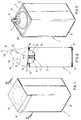
- Figure 1 is a schematic, axonometric view of a container for liquids according to the invention, in the closed state;
- Figure 2 is a schematic view in a midline section, along the line II-II of Figure 1, showing a series of positions of the peelable covering diaphragm, during opening;
- Figure 3 is a schematic, axonometric view as in Figure 1, of the open container ready for use;
- Figure 4 is a scheme of the manufacturing process for the container according to the invention, showing in particular application of the spouts to the respective top frames;
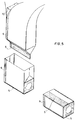
- Figure 5 schematically shows the container forming stage.
-
- With reference to said drawings, and for the moment in particular to Figures 1 and 3, the container for liquid products, particularly beverages, doughy products and the like according to the invention has been indicated as a whole by
reference numeral 1 and is substantially parallelepiped in shape. - It is made of flexible sheet material with one or more layers, substantially according to the teachings of the cited European patent No. 522 326.
- At the top and bottom faces of the container, inside the
flexible material 2 of which it is made, an upper or coveringframe 3 and a lower or base frame or bottom 4 are applied, advantageously by welding, and in this case are in the form of a rectangular or square frame, depending upon the shape of thecontainer 1 in horizontal section. - Structurally, the
container 1 has respectivevertical folds 5 on the two opposite side walls (see in particular Figures 1 and 3), and ahorizontal fold 6 is provided on a third side wall of the container, as shown in Figure 2. - The
frames 3 and 4 and thefolds container 1, which would otherwise be soft. - According to the invention, the
top frame 3 is connected to aflexible membrane 10, in the center of which is applied aspout 11 for dispensing the liquid held in thecontainer 1. - The free end of the
spout 11 is sealed tight by a bellows-type flap 12 connected on the inside to a peelable coveringdiaphragm 13 that covers the top wall of the container and has apull tab 14, such as to facilitate its removal. - During packaging of the
container 1, the flexible ordeformable membrane 10 is turned to the inside thereof, forming ahousing 15 for thespout 11, such that the end of the latter does not protrude beyond the plane of thetop frame 3. - Opening of the container takes place by pulling the
peelable diaphragm 13 upward, gripping thepull tab 14, as shown schematically by the sequence of positions shown in Figure 2. During this stage, the bellows-type tab 12, as it extends, maintains thespout 11 in a substantially vertical position, causing complete raising thereof when the diaphragm is torn by pulling it upward, also causing detachment of the bellows-type tab from the spout. - In the open state, the
container 1 appears as shown in Figure 3, that is with theflexible membrane 10 turned upwards on the outside of the container and thespout 11 completely free, so as to be readily be gripped between the lips of the user for consumption of the product in thecontainer 1. This operation can be further facilitated by gently squeezing the container with a hand. - In the same way, the liquid in the
container 1 can be poured into another recipient such as a glass. - In a variant embodiment, the
spout 11 could be connected directly to thepeelable diaphragm 13. However, in this case, during removal of thediaphragm 13 the spout would tend to fold toward theedge 16 of thecontainer 1, in the direction of which the pulling force is exerted on thediaphragm 13, as shown schematically by the arrows in Figure 2. - As far as the materials used are concerned, the
package 2 of the container, the bellows-type tab 12 and thepeelable diaphragm 13 are made of flexible multi-layer sheet material, for example polyester-aluminium-polyethylene, theframes 3, 4 and thespout 11 of weldable plastic material, and themembrane 10 of a material that can easily be deformed, for example thermally, such as a mixture of polyamide and polyethylene. - With the aid now of Figure 4 the manufacturing procedure of the
container 1 according to the invention, in particular the part of the procedure relating to application of thespout 11, is schematically illustrated. - Starting from a reel 30', a
sheet 30 of flexible material used to make themembranes 10 is unrolled. - Immediately downstream of a drawing wheel 31 a
punching station 32 able to make holes 60 on thesheet 30 for insertion of thespouts 11 is provided. Thepunching station 32 is followed by anapplication station 33 for theframes 3, which are positioned on the sheet from above. - There then follows an application and
welding station 34 for thespouts 11, which are inserted from below into the holes 60 made in thepunching station 32. Thespouts 11 have a widened base 11' for better welding to thesheet 30. - The
station 34 is followed by apre-heating station 35, a preheating station withinitial deformation 36, in which theflexible membrane 10 begins to be formed through deformation of thesheet 30 interposed between theframe 3 and the widened base 11' of thespout 11. Deformation is completed in adeformation station 37 followed by a possible second deformation station 37', where theflexible membrane 10 takes on the final shape shown in Figures 2 and 3. - The
sheet 30 then makes aloop 38 forming a storage unit for theframes 3 withspouts 11, at the exit of which is situated acutting station 39, which cuts the sheet along the outside of theframes 3, which are sent, together with the corresponding spouts, into aguide channel 40, along which at least onesterilization area 41 using ultraviolet rays or hydrogen peroxide is provided. - Simultaneously, the
flexible material 2 serving to form the package of thecontainer 1 is unrolled from areel 50 and fed to apunching station 51 where rectangular or square openings are made, slightly smaller in size than those of theframes 3, so that anedge 42 of theflexible material 2 is disposed around the perimeter in the surface of the of frame 3 (see in particular Figure 3). - The
frames 3 with thespouts 11 are fed to astation 52 immediately downstream of thepunching station 51, in which they are positioned in the punchedpart 53 of theflexible sheet material 2 and subjected to pre-welding, for example on two sides. Astation 54 for complete welding of theframes 3 on saidouter edge 42 of thesheet 2 then follows. - Downstream of the
station 54 anapplication station 55 is provided for the peelable membrane, possibly prepared with the bellows-type tab 12, followed by an easy-open welding station 56. - The
sheet 2 provided with theframes 3 andrelative spouts 11, as well as with the base frames 4, application of which has not been shown in Figure 4, but which takes place in a similar way to application of theframes 3, is sent to thecontainer forming station 1, as described in the cited European patent No. 522.326, and finally to filling. - As shown schematically in Figure 5, forming of the
containers 1 takes place around avertical mandrel 70, where welding andfolding 6 are carried out giving rise to a tube open at the two sides of the container in which the two lines of welding and folding will subsequently be made. While the tube comes off from the mandrel, welding and folding 5 is carried out at the bottom, and the tube is then cut at the pre-established height, so as to obtain containers open on one side, which are sent for filling and then closed by further welding and folding 5. - From the foregoing the advantages of the container for liquids and similar products according to the invention are apparent.
Claims (7)
- A container of flexible material particularly for liquid products, with a substantially parallelepiped shape, consisting of a flexible package (2) and having a frame (3) at least at its upper face, said frame (3) taking the form of a peripheral rim, characterized in that in the center of said frame is situated a spout (1 1), connected to the frame by means of a flexible membrane (10) turned to the inside of the container (1) during packaging so as to form a housing (15) for the spout (11) and which, together with the spout, can be turned to the outside of the container (1) during use, at least the end of the spout (11) being sealed with a liquid-tight seal.
- A container according to claim 1, characterized in that the upper face of the container (1) is covered by a peelable diaphragm (13), provided with a pull tab (14) to facilitate removal thereof.
- A container according to claim 2, characterized in that said peelable diaphragm (13) is connected to said spout (11) and closes the end thereof with a tight seal.
- A container according to claim 2 or 3, characterized in that said peelable diaphragm (13) is connected to said spout (11) by means of a bellows-type tab (12), able to cause more or less vertical raising of the spout during removal of the diaphragm.
- A container according to any one of the preceding claims, characterized in that said flexible membrane (10) is a plastic membrane that can be deformed, provided with a central hole (60) where the spout (11) is housed, welded to a base flange (11') of the spout and around the perimeter of the frame (3).
- A container according to any one of the preceding claims, characterized in that it also has a frame (4) inside its bottom face, two vertical folding and welding lines (5) on two opposite sides, and a horizontal welding and folding line (6) on a third side.
- A method for manufacturing containers for liquid products according to any one of the preceding claims, comprising the stages of:feeding a sheet of flexible material (30) for forming said membranes (10);making holes (60) in said sheet (30);applying frames (3) around said holes (60);inserting spouts (11) into said holes (60) and welding the respective bases (11') to the sheet (30);pre-heating and deformation of the portion of sheet comprised between each spout (11) and the corresponding frame (3) to create said flexible membrane (10);cutting the sheet (30) along the outer edge of each frame (3);feeding the frames (3) with respective spouts (11) to a strip of flexible sheet material (2);positioning and welding said frames (3) at the respective punched windows in the sheet (2);applying and welding a peelable diaphragm (13) possibly with a bellows-type tab (12) to the framesending the sheet (2) after possible application of the base frames (4) to a vertical mandrel (70), where a tube is formed by closing the web along a welding and folding line (6), and then an open container by making a weld and fold (5) and cutting the tube at the desired height.
Applications Claiming Priority (2)
| Application Number | Priority Date | Filing Date | Title |
|---|---|---|---|
| ITMI980659 | 1998-03-27 | ||
| ITMI980659 IT1298961B1 (en) | 1998-03-27 | 1998-03-27 | CONTAINER IN FLEXIBLE MATERIAL, PARTICULARLY FOR LIQUID OR SIMILAR PRODUCTS, AND RELATED PRODUCTION METHOD. |
Publications (2)
| Publication Number | Publication Date |
|---|---|
| EP0945361A2 true EP0945361A2 (en) | 1999-09-29 |
| EP0945361A3 EP0945361A3 (en) | 2000-06-14 |
Family
ID=11379551
Family Applications (1)
| Application Number | Title | Priority Date | Filing Date |
|---|---|---|---|
| EP99105524A Withdrawn EP0945361A3 (en) | 1998-03-27 | 1999-03-18 | Container of flexible material, particularly for liquid products or the like, and relative method of manufacture |
Country Status (2)
| Country | Link |
|---|---|
| EP (1) | EP0945361A3 (en) |
| IT (1) | IT1298961B1 (en) |
Cited By (4)
| Publication number | Priority date | Publication date | Assignee | Title |
|---|---|---|---|---|
| FR2850087A1 (en) * | 2003-01-20 | 2004-07-23 | Michel Guillot | Packaging for food or pharmaceuticals has capsule with threaded closure and removable seal |
| WO2004078597A2 (en) | 2003-02-28 | 2004-09-16 | Michel Guillot | Interior safety capsules |
| WO2007071237A1 (en) * | 2005-12-21 | 2007-06-28 | Columbus E. Aps | Disposable beverage can |
| CN101186143B (en) * | 2006-11-20 | 2010-12-22 | 海德堡印刷机械股份公司 | Anilox roller printing device and printer |
Citations (1)
| Publication number | Priority date | Publication date | Assignee | Title |
|---|---|---|---|---|
| EP0522326A1 (en) | 1991-06-27 | 1993-01-13 | Luigi Goglio | A flexible material container and related production method |
Family Cites Families (3)
| Publication number | Priority date | Publication date | Assignee | Title |
|---|---|---|---|---|
| FR1187198A (en) * | 1957-11-19 | 1959-09-08 | Uniplax | Plastic containers with attached bottoms |
| US3559847A (en) * | 1968-03-20 | 1971-02-02 | Eugene E Goodrich | Collapsible sanitary container with retractable spout |
| US5816428A (en) * | 1994-09-28 | 1998-10-06 | The Coca-Cola Company | Easy-open can end and spout |
-
1998
- 1998-03-27 IT ITMI980659 patent/IT1298961B1/en active IP Right Grant
-
1999
- 1999-03-18 EP EP99105524A patent/EP0945361A3/en not_active Withdrawn
Patent Citations (1)
| Publication number | Priority date | Publication date | Assignee | Title |
|---|---|---|---|---|
| EP0522326A1 (en) | 1991-06-27 | 1993-01-13 | Luigi Goglio | A flexible material container and related production method |
Cited By (5)
| Publication number | Priority date | Publication date | Assignee | Title |
|---|---|---|---|---|
| FR2850087A1 (en) * | 2003-01-20 | 2004-07-23 | Michel Guillot | Packaging for food or pharmaceuticals has capsule with threaded closure and removable seal |
| WO2004078597A2 (en) | 2003-02-28 | 2004-09-16 | Michel Guillot | Interior safety capsules |
| WO2004078597A3 (en) * | 2003-02-28 | 2005-01-27 | Michel Guillot | Interior safety capsules |
| WO2007071237A1 (en) * | 2005-12-21 | 2007-06-28 | Columbus E. Aps | Disposable beverage can |
| CN101186143B (en) * | 2006-11-20 | 2010-12-22 | 海德堡印刷机械股份公司 | Anilox roller printing device and printer |
Also Published As
| Publication number | Publication date |
|---|---|
| EP0945361A3 (en) | 2000-06-14 |
| ITMI980659A1 (en) | 1999-09-27 |
| IT1298961B1 (en) | 2000-02-07 |
Similar Documents
| Publication | Publication Date | Title |
|---|---|---|
| US11447299B2 (en) | Flexible material for flexible package | |
| EP0442299B1 (en) | Flexible pouch with folded spout | |
| US5758473A (en) | Method for manufacturing packages for liquid products, especially liquid foodstuffs and a package obtained through this method | |
| JP2892716B2 (en) | Opening device for packaging containers | |
| US5199618A (en) | Pouring device for container for flowable material | |
| FI79501C (en) | Procedure for the preparation of food and beverage containers, apparatus for carrying out the process and containers made according to the procedure | |
| US6685058B2 (en) | Film for dispenser package in the form of a pouch with a flap | |
| US20070133909A1 (en) | Beverage container | |
| AU644288B2 (en) | Reclosable pouch and method and apparatus for forming, filling and sealing | |
| EP0442292A1 (en) | Flexible pouch with folded spout | |
| RU2091279C1 (en) | Pourout device and method of its manufacture | |
| US6481889B2 (en) | Sealed enclosure, method for the manufacture thereof, and method of packaging a beverage in said enclosure | |
| EP0675053B1 (en) | Process for making container of plastified sheet material and container obtained with this process | |
| JPH02127243A (en) | Carton almost impervious to liquid and apparatus and method for holding pour-out section | |
| CA2603917A1 (en) | Packing bag with outer packing | |
| US5832698A (en) | Method of manufacturing a flexible package comprising a pouring channel, and package obtained by the method | |
| US4666064A (en) | Dispensing device for "bag-in-box" packages, bag and device for filling bags | |
| JPH0788061B2 (en) | Liquid container and method for treating spout of liquid container | |
| JPS6039013B2 (en) | Method for obtaining an opening device with good pouring properties for packaging containers | |
| EP0945361A2 (en) | Container of flexible material, particularly for liquid products or the like, and relative method of manufacture | |
| JP4320085B2 (en) | Bag making method and device for indefinite container with spout | |
| US6854490B2 (en) | Flexible pouch with self-contained straw and method of forming | |
| JPH07315375A (en) | Paper container | |
| JPH09500073A (en) | Improved container opening device | |
| WO1996015040A1 (en) | Pouch with reinforcing means for delivery tube |
Legal Events
| Date | Code | Title | Description |
|---|---|---|---|
| PUAI | Public reference made under article 153(3) epc to a published international application that has entered the european phase |
Free format text: ORIGINAL CODE: 0009012 |
|
| AK | Designated contracting states |
Kind code of ref document: A2 Designated state(s): AT BE CH CY DE DK ES FI FR GB GR IE IT LI LU MC NL PT SE |
|
| AX | Request for extension of the european patent |
Free format text: AL;LT;LV;MK;RO;SI |
|
| PUAL | Search report despatched |
Free format text: ORIGINAL CODE: 0009013 |
|
| AK | Designated contracting states |
Kind code of ref document: A3 Designated state(s): AT BE CH CY DE DK ES FI FR GB GR IE IT LI LU MC NL PT SE |
|
| AX | Request for extension of the european patent |
Free format text: AL;LT;LV;MK;RO;SI |
|
| RIC1 | Information provided on ipc code assigned before grant |
Free format text: 7B 65D 75/58 A, 7B 65D 47/06 B |
|
| AKX | Designation fees paid | ||
| REG | Reference to a national code |
Ref country code: DE Ref legal event code: 8566 |
|
| STAA | Information on the status of an ep patent application or granted ep patent |
Free format text: STATUS: THE APPLICATION IS DEEMED TO BE WITHDRAWN |
|
| 18D | Application deemed to be withdrawn |
Effective date: 20001215 |