EP0945008B1 - Lichtabschirmung für neben- oder übereinander angeordnete bildwiedergabeeinrichtungen - Google Patents
Lichtabschirmung für neben- oder übereinander angeordnete bildwiedergabeeinrichtungen Download PDFInfo
- Publication number
- EP0945008B1 EP0945008B1 EP97949847A EP97949847A EP0945008B1 EP 0945008 B1 EP0945008 B1 EP 0945008B1 EP 97949847 A EP97949847 A EP 97949847A EP 97949847 A EP97949847 A EP 97949847A EP 0945008 B1 EP0945008 B1 EP 0945008B1
- Authority
- EP
- European Patent Office
- Prior art keywords
- light shield
- sections
- modular light
- section
- wall
- Prior art date
- Legal status (The legal status is an assumption and is not a legal conclusion. Google has not performed a legal analysis and makes no representation as to the accuracy of the status listed.)
- Expired - Lifetime
Links
Images



Classifications
-
- H—ELECTRICITY
- H04—ELECTRIC COMMUNICATION TECHNIQUE
- H04N—PICTORIAL COMMUNICATION, e.g. TELEVISION
- H04N9/00—Details of colour television systems
- H04N9/12—Picture reproducers
- H04N9/31—Projection devices for colour picture display, e.g. using electronic spatial light modulators [ESLM]
- H04N9/3141—Constructional details thereof
- H04N9/3147—Multi-projection systems
Definitions
- the present invention relates to a modular, convertible light shield for image reproduction devices which comprise projectors and screens, an image being projected onto the rear side of a screen with the aid of a projector.
- the field of application is that of modular multi-screen displays.
- a multi-screen display of this kind the viewer is situated in front of the screens, which are positioned next to and/or above one another, optionally at an angle, with the result that they form an image surface onto which an image, optionally composed of a plurality of subimages, can be projected.
- a subimage may cover one or more screens of the image surface and may appear at any desired location on the image surface. These subimages may be projected dependently or independently.
- the images may be moving or stationary.
- modular multi-screen displays which are provided with a light shield between the various image reproduction devices, for example from EP-A1-0,650,295 or DE-U1-8911547.3.
- the basic principle of existing modular light shields is always the same.
- the conventional convertible multi-screen display is constructed by stacking a number of identical basic units on top of and/or next to one another. Each of the basic units is composed of:
- a light shield as outlined above is, as it were, a type of box, with an inner edge and an outer edge.
- the light beams emanating from the projector, which together with the light shield form a basic unit, are guided by the inner edge of the light shield so that they reach the rear side of the corresponding screen.
- the rear side of the screen is that side which is situated on the projector side, and thus not on the viewer side.
- two light shield walls one belonging to each basic unit. If two such basic units are stacked on top of one another, these walls are the top wall of the bottom unit and the bottom wall of the top unit; if they are stacked next to one another, these walls are the left-hand wall of the right-hand basic unit and the right-hand wall of the left-hand basic unit. Only one wall is required in order to provide suitable light shielding. The presence of two light shield walls is not only a waste of material but also results in surplus weight of the complete arrangement. This extra weight also has to be transported, thus entailing extra transport costs.
- Known multi-screen displays are constructed by stacking the basic units on top of one another. They are fastened together automatically, manually or are not fastened together. If basic units stacked next to one another are not joined together, there is a high risk of vertical gaps appearing. If they are joined together manually, long screws are often used, which are not always as easy to remove.
- a multi-screen display is constructed using the basic units which are known from the prior art, it is only possible to create one or more passages in the multi-screen display, with one or more basic units arranged above a passage, by making use of extra structural elements. These extra structural elements may be a suspension arrangement, a support or extra connections to the adjacent basic unit or units.
- the object of designing the present invention is to eliminate the abovementioned drawbacks and to provide a system which is modular and is easy to set up and dismantle.
- the modular light shield between image reproduction devices according to the invention is built up by walls, so that only one wall is present between two adjacent image reproduction devices. These walls are kept in position by means of horizontal, vertical and lateral sections, which are each provided with at least one groove in the longitudinal direction. Fastening elements are provided for connecting the sections with each other.
- a modular light shield according to the invention can be set up between image reproduction devices in a very simple manner.
- a base is first constructed from sections, walls and fastening elements and is adjusted until it is completely level. These sections, walls and fastening elements may be pre-assembled in advance to form units.
- the base can be levelled, for example, by attaching the base of the multi-screen display to vertically adjustable legs.
- the complete arrangement of the multi-screen display on the base is preferably constructed using pre-assembled units.
- the pre-assembled units of the multi-screen display are likewise composed of sections, walls and fastening elements. Vertical, horizontal and lateral sections respectively determine the height and the width of the screens and the depth of a unit.
- the corner connections between sections are made such that, after assembly, the light beams emanating from the projector can reach the complete screen without hindrance.
- This is possible, inter alia, by not arranging a fastening element directly between a horizontal and a vertical section, but rather by joining both the horizontal and the vertical section to a lateral section.
- Other fastening means which do not protrude from the section, or do so only to a limited extent, are known to the person skilled in the art and can be used as fastening elements in the present invention.
- the sections are extruded sections.
- the cross-section of the sections is substantially square.
- each section is provided with at least one groove on each side in the longitudinal direction of the section.
- these grooves are T-grooves or dovetail grooves.
- the walls of the modular light shield between image reproduction devices may be made from sheet material (such as plastic, metal or cardboard), fabric or film.
- the walls are preferably held in the grooves, between the sections of the light shield.
- the walls are preferably folded aluminium sheets which are fastened between the sections.
- the fastening elements are used to join the various sections together.
- the type of fastening elements used depends on the sections used and on the grooves which are made therein.
- the fastening elements comprise one of the following combinations: 1 corner piece + 2 coach bolts + 2 nuts; 1 corner piece + 2 quick-acting closures; 1 corner piece + 1 quick-acting closure + 1 coach bolt + 1 nut.
- fastening flange with 2 screws with hexagon sockets and a double sliding nut, which can optionally be screwed in place; 1 corner piece + 2 coach nuts + 2 bolts; 1 corner piece + 1 quick-acting closure + 1 coach nut + 1 bolt; at least 1 screw; at least 1 quick-acting closure; ...
- the sections, the walls and the fastening elements may all be well-defined components whose properties are very well known. This is important in order to be able to know how much each connection can support, so that with high structures, if necessary, certain sections can be replaced by similar but stronger sections. In this case, the other structural elements do not have to be changed, or do not have to be changed much.
- the various components can be packaged and dispatched either completely separately (CKD) or pre-mounted (SKD). In both cases, everything can be stacked close together, so that a maximum of components can be transported in a minimum of space. This is an important factor in reducing transport costs.
- the light shield according to the invention has the significant advantage that it is lightweight, owing to the single partition which shields the light between image reproduction devices which bear against one another.
- the light shield is very suitable for renting out, since the installation is easy to set up and dismantle. However, it is also suitable for fixed or semi-fixed installations. The latter are installations which are normally fixed but, for example for major events, are extended or reconfigured. This is because it is very easy to add a row or column to the modular light shield according to the invention.
- the light shield is constructed in a modular, rapid and simple manner. It is also simple to dismantle and to convert a certain multi-screen display to a different configuration, all this without damaging the components.
- the separate components can be assembled in a simple manner (using a plan, gauge, ...) to form pre-mounted modules or to form a complete wall.
- the system may be provided with various possibilities for suspending the arrangement. For example, if the upper horizontal .sections and lateral sections are provided with a T-groove on the top, it is possible, for example, to attach a suspension system comprising eye nuts which are fixed to coach bolts.
- the vertical pillars of the display may be constructed completely by vertical sections, without interruption from horizontal or lateral sections. If the vertical sections are provided with a hole, an eye screw or a steel cable may be arranged therein in order to take care of the suspension.
- the sections which are situated along the outside of the multi-screen display would not have to be provided with a groove along that side.
- the grooves in the horizontal sections on the front can be used for attaching the screens. This results in screens which are easy to attach and detach and are easy to clean, even on the inside.
- the wall is sufficiently large as soon as light emanating from a first projector is prevented from being incident on a screen belonging to a second projector. This may allow the walls which form the light shield between two adjacent projectors to be made less deep.
- the modular light shield 1 is composed of sections 2, walls 3 and fastening elements 4 ( Figure 2). In the embodiment shown, these basic pieces are used to form a modular light shield 1 for a multi-screen display which is two image reproduction devices wide and two image reproduction devices high. Owing to the modular nature of the invention, the arrangement is not limited to 2 x 2 or M x M, but rather M x N (where M and N are integers) or other symmetrical and asymmetrical combinations are possible.
- the sections 2 are bar-shaped extruded sections ( Figure 3), the cross-section of which is substantially square and which are provided with a T-groove 10 on each side in the longitudinal direction of the section 2.
- Figure 3 An advantage of using extruded sections is that it is not necessary to undertake major changes to the light shields 1 if the dimensions of the image reproduction devices are changed. The same sections 2 can be used, and they simply have to be sawn off to a different length.
- the extruded section shown in Figure 3 is provided with a hole 13, which if necessary can be used to suspend the multi-screen display.
- the same extruded sections are used for the horizontal, vertical and lateral sections, where necessary sawn to different lengths.
- the walls 3 consist of sheet material.
- the special shape of the wall 3 as shown in Figure 4 allows the wall to be fixed, on the one hand, by the raised edges 11 of the wall 3 in the T-grooves 10 of the sections 2 and, on the other hand, by the corners 12 of the wall 3 behind the fastening elements 4 of the light shield 1 (cf. also Figure 5a).
- a wall 3 is formed by a planar sheet, it can be fastened (cf. Figure 5b) by allowing it to lie in a recess 14 in the section 2. The wall 3 should then be fixed to the fastening elements 4, for example with the aid of screws 23.
- the fastening elements 4 are used to fasten together two sections 2.
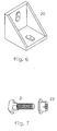
- use is made of a corner piece 20, coach bolts 21 and nuts 22 (cf. also Figures 6 and 7).
- the connections between the various sections can thus be achieved very easily.
- Other fastening elements for making the desired connections are also commercially available.
- the abovementioned basic pieces (sections 2, walls 3 and fastening elements 4) can be assembled in advance, in order to simplify the in situ assembly of a modular light shield 1 and to make this assembly less time-consuming.
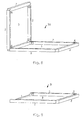
- a possible method of pre-assembly is to form the following basic modules: a starter element 30, horizontal structural elements 31, vertical structural elements 32 and honeycomb elements 33 ( Figures 8 to 11).
- a starter element 30 horizontal structural elements 31, vertical structural elements 32 and honeycomb elements 33 ( Figures 8 to 11).
- the grooves 10 are not shown in these figures.
- the assembly shown in the figures is carried out using folded aluminium sheets, but can also be carried out using planar sheets which are set in recesses.
- the starter element 30 ( Figure 8) comprises 7 sections 2, which are disposed in such a manner that they form an L, in which the distance between the lateral sections of the upright limb plus the height of one lateral section is equal to the height of an image reproduction device, and in which the distance between the lateral sections of the horizontal limb plus the width of the lateral section is equal to the width of one image reproduction device.
- Two walls 3, an upright wall and a horizontal wall, are already arranged between the sections 2.
- a horizontal structural element 31 ( Figure 9) comprises three sections 2, between which a wall 3 is arranged. Three of the four sides of the horizontal structural element 31 are thus closed off by a section 2, while the fourth side is open.
- This horizontal structural element 31 is intended to be arranged horizontally against a starter element 30 or against another horizontal structural element 31 ( Figure 12).
- Fastening elements 4 are already arranged on the open side of the horizontal structural element 31, so that it can be joined to another basic module easily and quickly by tightening just two nuts 22 (one on each corner piece 20) onto the corresponding coach bolts 21.
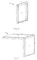
- a vertical structural element 32 ( Figure 10) likewise comprises three sections 2, between which a wall 3 is arranged. Three of the four sides of the vertical structural element 32 are thus closed off by a section 2, while the fourth side is open.
- This vertical structural element 32 is intended to be arranged vertically above a starter element 30 or above another vertical structural element 32 ( Figure 12).
- two fastening elements 4 are already arranged on the open side of the vertical structural element 32, so that it can easily be joined to another basic module, likewise by tightening just two nuts 22 onto the corresponding coach bolts 21.
- a honeycomb element 33 ( Figure 11) is assembled from five sections 2 and two walls 3.
- This honeycomb element 33 is likewise L-shaped, both limbs being "open", i.e. not provided with a section 2 on their free end.
- two fastening elements 4 are already arranged on each open side (two open sides) of the honeycomb element 33, so that an open side can easily be joined to the starter element 30, to a neighbouring horizontal structural element 31, a neighbouring vertical structural element 32 or a neighbouring honeycomb element 33, by tightening just two nuts 22 onto the corresponding coach bolts 21.
- Each basic module 31, 32, 33 can be constructed in various ways; the vertical sections may continue to the highest or lowest point of the basic module, or may not do so, the horizontal sections may continue to the furthest point of the basic module, or may not do so, the lateral sections may continue to the front and/or rear side of the basic module, or may not do so. In this case, whether sections continue to the front and rear sides of a basic module may differ.
- the modular light shield 1 is assembled as described below ( Figure 12).
- a starter element 30 is positioned at the bottom left, after which a number of horizontal structural elements 31 are arranged and fixed to the right of it, until the required width of the multi-screen display, i.e. of the modular light shield 1, is reached.
- the unit obtained in this way is adjusted until it is completely level. This can be carried out, for example, by means of legs 40 which can be screwed out.
- the vertical structural elements 32 are arranged and fixed on top of the starter element 30, until the required height of the modular light shield 1 is reached, and then the honeycomb elements 33 are arranged and fixed.
- Each connection which is to be made is carried out simply by screwing a nut 22 tightly onto the corresponding coach bolt 21.
- the complete arrangement can be constructed with the aid of honeycomb elements 33 (which are positioned upside down with respect to the arrangement shown in Figure 12), after which top walls 50 are arranged at the top, side walls 51 at the sides and finally a closing module 52 (Figure 13a) or a closing section 53 (Figure 13b) is attached.
- a closing module 52 Figure 13a
- a closing section 53 Figure 13b
- NxM honeycomb elements 33 are required, as well as M-1 top walls 50, N-1 side walls 51 and one closing module 52.
- NxM honeycomb elements 33 are required, M top walls 50, N side walls 51 and one closing section 53.
- Figure 13c Another possibility is to assemble only one type of honeycomb elements 33 in advance, and to provide lateral sections 54. This can only be used for an MxM arrangement. In that case, Mx(M+1) honeycomb elements 33 need to be assembled in advance. Furthermore, M+1 lateral sections 54 are also required for final assembly, which consists in constructing a triangle of honeycomb elements 33, M high, M wide, which are all placed in the same direction. Lateral sections 54 are then arranged on all open sides, after which the remaining honeycomb elements 33 are attached in an inverted manner.
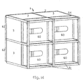
- a rear wall 60 (Figure 14) of the modular light shield 1 may be optionally pre-mounted.
- Figure 14 shows another preferred embodiment of a light shield 1 according to the invention, namely a light shield 1 which is provided with a support surface 61 for the projectors.
- the lateral sections 54 of the light shield 1 continue towards the rear, and three vertical sections 2 are mounted per vertical light shield wall, instead of two. Possibly, an extra horizontal section 2 may also be mounted beneath each rear wall 60.
- the support or supports which form the support surface 61 for the projector may be optionally pre-mounted directly or indirectly on the horizontal and/or on the lateral and/or on the vertical sections 2. The position of the support surface 61 for the projector depends on the projector and the size of the screen 62.
- the lateral sections do not have to continue all the way to the rear, but rather it is possible, for example, to attach an extra lateral section of a different length to the rear horizontal section.
- the support surface 61 for the projector may be optionally pre-mounted directly or indirectly on the light shield in countless different ways.
- the support surface 61 may have any desired form.
- the projectors After mounting the light shield 1, the projectors are placed on or suspended from the support surfaces 61. Each projector will transmit an image through a hole in the rear wall 60 onto the corresponding screen 62.
Landscapes
- Engineering & Computer Science (AREA)
- Multimedia (AREA)
- Signal Processing (AREA)
- Overhead Projectors And Projection Screens (AREA)
- Transforming Electric Information Into Light Information (AREA)
Claims (12)
- Modulare Lichtabschirmung (1) zwischen Bildwiedergabeeinrichtungen, welche durch Wände (3) so aufgebaut sind, dass nur eine Wand (3) zwischen zwei angrenzenden Bildwiedergabeeinrichtungen vorhanden ist, dadurch gekennzeichnet, dass die Wände (3) mittels horizontalen, vertikalen und seitlichen Profilen (2) in Position gehalten werden, wobei jedes Profil (2) mit mindestens einem Schlitz (10) in Längsrichtung des Profils (2) versehen ist, und dass Befestigungselemente (4), welche durch die Schlitze (10) in Eingriff genommen werden können, zum Verbinden der Profile (2) miteinander vorgesehen sind
- Modulare Lichtabschirmung (1) nach Anspruch 1, dadurch gekennzeichnet, dass die Abschnitte (2) Strangpressprofile sind.
- Modulare Lichtabschirmung (1) nach einem der vorhergehenden Ansprüche, dadurch gekennzeichnet, dass der Querschnitt der Profile (2) im wesentlichen quadratisch ist.
- Modulare Lichtabschirmung (1) nach einem der vorhergehenden Ansprüche, dadurch gekennzeichnet, dass die Profile (2) mit mindestens einem Schlitz (10) auf jeder Seite in Längsrichtung des Profils (2) versehen sind.
- Modulare Lichtabschirmung (1) nach einem der vorhergehenden Ansprüche, dadurch gekennzeichnet, dass die Schlitze (10) T-Schlitze oder Schwalbenschwanzschlitze sind.
- Modulare Lichtabschirmung (1) nach einem der vorhergehenden Ansprüche, dadurch gekennzeichnet, dass die Wände (3) aus einem Material hergestellt sind, welches aus einem Blech, Stoff oder einer Kunststofffolie ausgewählt ist.
- Modulare Lichtabschirmung (1) nach einem der vorhergehenden Ansprüche, dadurch gekennzeichnet, dass die Profile (2) mit mindestens einer Auskehlung (14) versehen sind, in welcher sich eine Wand (3) befindet.
- Modulare Lichtabschirmung (1) nach einem der Ansprüche 1 bis 5, dadurch gekennzeichnet, dass die Wände (3) gefaltete Aluminiumbleche sind, deren umgefaltete Seite in einem Schlitz (10) eines Profils (2) gehalten wird.
- Modulare Lichtabschirmung (1) nach einem der vorhergehenden Ansprüche, dadurch gekennzeichnet, dass die Befestigungselemente (14) aus den folgenden Kombinationen ausgewählt sind: Eckstück (20) + 2 Schlossschrauben (21) + 2 Schraubenmuttern (22), Eckstück (20) + 2 Schnellverschlüsse, Eckstück (20) + 1 Schnellverschluss + 1 Schlossschraube (21) + 1 Schraubenmutter (22).
- Modulare Lichtabschirmung (1) nach einem der vorangehenden Ansprüche, dadurch gekennzeichnet, dass sie mit einer Vorrichtung zum Aufhängen der Einheit versehen ist.
- Modulare Lichtabschirmung (1) nach einem der vorangehenden Ansprüche, dadurch gekennzeichnet, dass sie mit Auflageflächen (61) für die Projektoren versehen ist.
- Verfahren zum Konstruieren einer modularen Lichtabschirmung (1), so dass nur eine Wand zwischen zwei angrenzenden Bildwiedergabeeinrichtungen vorhanden ist, dadurch gekennzeichnet, dass es die folgenden Schritte umfasst:a) Konstruieren einer Grundfläche,b) Justieren der Grundfläche, bis sie eben ist,c) Konstruieren der Lichtabschirmung (1) mit Hilfe der im voraus zusammengebauten Einheiten (30, 31, 32, 33), welche mindestens eine Wand (3) und mindestens ein Profil (2) umfassen, wobei das Profil (2) mit mindestens einem Schlitz (10) in Längsrichtung des Profils versehen ist, wobei die Wand (3) mit dem Profil (2) verbunden ist, die Konstruktion durch Verbinden verschiedener Profile (2) mittels der Befestigungselemente (4)ausgeführt wird, welche durch die Schlitze (10) in Eingriff genommen werden können,d) Anbringen von mindestens zwei Bildschirmen (62), unde) Anbringen von mindestens zwei Projektoren.
Applications Claiming Priority (3)
| Application Number | Priority Date | Filing Date | Title |
|---|---|---|---|
| BE9601054 | 1996-12-17 | ||
| BE9601054A BE1010811A5 (nl) | 1996-12-17 | 1996-12-17 | Lichtafscherming voor naast en/of boven elkaar geplaatste beeldweergave-inrichtingen. |
| PCT/BE1997/000137 WO1998027726A1 (en) | 1996-12-17 | 1997-12-16 | Light shield for image reproduction devices placed next to and/or above one another |
Publications (2)
| Publication Number | Publication Date |
|---|---|
| EP0945008A1 EP0945008A1 (de) | 1999-09-29 |
| EP0945008B1 true EP0945008B1 (de) | 2004-03-10 |
Family
ID=3890154
Family Applications (1)
| Application Number | Title | Priority Date | Filing Date |
|---|---|---|---|
| EP97949847A Expired - Lifetime EP0945008B1 (de) | 1996-12-17 | 1997-12-16 | Lichtabschirmung für neben- oder übereinander angeordnete bildwiedergabeeinrichtungen |
Country Status (5)
| Country | Link |
|---|---|
| EP (1) | EP0945008B1 (de) |
| AU (1) | AU5305098A (de) |
| BE (1) | BE1010811A5 (de) |
| DE (1) | DE69728059T2 (de) |
| WO (1) | WO1998027726A1 (de) |
Families Citing this family (2)
| Publication number | Priority date | Publication date | Assignee | Title |
|---|---|---|---|---|
| FR2853511B1 (fr) * | 2003-04-08 | 2005-06-10 | Systel Electronique | Dispositif d'integration de moniteurs dans des structures de monitorage |
| DE102008033756A1 (de) | 2007-07-27 | 2009-03-05 | Ldt Laser Display Technology Gmbh | Verfahren und Anordnung zum Projizieren eines Bildes auf eine Projektionsfläche |
Family Cites Families (8)
| Publication number | Priority date | Publication date | Assignee | Title |
|---|---|---|---|---|
| US3661434A (en) * | 1970-05-28 | 1972-05-09 | Ralph Alster | Unitary modular shelving structure |
| US4123129A (en) * | 1976-11-18 | 1978-10-31 | Tektronix, Inc. | Modular electronic instrument cabinets |
| JPH0787561B2 (ja) * | 1988-03-08 | 1995-09-20 | パイオニア株式会社 | プロジェクションテレビユニット及びマルチプロジェクションテレビの連結部材 |
| FR2641586B1 (fr) * | 1989-01-12 | 1991-04-26 | Marot Jacques | Dispositif de support associe a un profile, en particulier pour supporter une tablette ou entretoise d'element modulaire ou demontable |
| DE8911547U1 (de) * | 1989-09-28 | 1989-11-09 | Delcom GmbH Deutsche Video-Digitalisierungssysteme, 8500 Nürnberg | Video-Präsentationsvorrichtung |
| IT1244081B (it) * | 1990-11-21 | 1994-07-05 | Arredi Tecnici Villa Spa | Sistema modulare per la realizzazione di pareti attrezzate e banchi dilavoro in particolare per laboratori. |
| EP0523427B1 (de) * | 1991-06-28 | 1997-03-26 | Matsushita Electric Industrial Co., Ltd. | Gehäuse für Projektionsfernsehempfänger und Verfahren zum Montieren eines Bildschirms |
| EP0650295B1 (de) * | 1993-10-21 | 1999-07-21 | Kabushiki Kaisha Toshiba | Mehrschirmanzeigevorrichtung und Verfahren zu deren Zusammenbau |
-
1996
- 1996-12-17 BE BE9601054A patent/BE1010811A5/nl not_active IP Right Cessation
-
1997
- 1997-12-16 WO PCT/BE1997/000137 patent/WO1998027726A1/en not_active Ceased
- 1997-12-16 DE DE69728059T patent/DE69728059T2/de not_active Expired - Lifetime
- 1997-12-16 AU AU53050/98A patent/AU5305098A/en not_active Abandoned
- 1997-12-16 EP EP97949847A patent/EP0945008B1/de not_active Expired - Lifetime
Also Published As
| Publication number | Publication date |
|---|---|
| DE69728059T2 (de) | 2004-11-04 |
| EP0945008A1 (de) | 1999-09-29 |
| AU5305098A (en) | 1998-07-15 |
| DE69728059D1 (de) | 2004-04-15 |
| WO1998027726A1 (en) | 1998-06-25 |
| BE1010811A5 (nl) | 1999-02-02 |
Similar Documents
| Publication | Publication Date | Title |
|---|---|---|
| AU672924B2 (en) | Corner junction for cabinet, and electrical cabinet comprising such junctions | |
| RU2134474C1 (ru) | Рамный каркас для распределительного шкафа | |
| RU2700001C2 (ru) | Модульный центр обработки данных и способ его формирования | |
| US8127505B2 (en) | Assembly type wall structure | |
| EP1012666B1 (de) | Projektionsschirm für bildreproduktionsvorrichtungen die neben/oder übereinander positioniert sind | |
| US10246868B2 (en) | Modular platform assembly and a method of assembling a modular platform | |
| EP3757442B1 (de) | Anzeigemodul für einen temporären ausstellungsstand | |
| US9003731B2 (en) | Modular wall nesting system | |
| DE69200255D1 (de) | Modulartrennwandsystem. | |
| BE1020560A3 (nl) | Profiel voor standenbouw, kader en standenbouwsamenstel. | |
| DE102009022479B4 (de) | Mobiles modulares Wandsystem | |
| US5249005A (en) | Projection image system and assembling system therefor | |
| US20100101155A1 (en) | Modular work station with air collector | |
| EP3358286A1 (de) | Verfahren und vorrichtung für einen modularen luft-luft-wärmetauscher | |
| EP0945008A1 (de) | Lichtabschirmung für neben- oder übereinander angeordnete bildwiedergabeeinrichtungen | |
| EP0625300B1 (de) | Verfahren zum ab- und zusammenbau von modulen in einer paneelstruktur und paneelstruktur mit verwendung dieses verfahrens | |
| JPH02147746A (ja) | 壁装置 | |
| US4359249A (en) | Display case and a modular display case system | |
| JPH08140023A (ja) | マルチビジョン | |
| RU140914U1 (ru) | Светодиодный экран с двухсторонним обслуживанием | |
| JPS6362749B2 (de) | ||
| GB2124269A (en) | Wall structure | |
| JPH0737556Y2 (ja) | 片面陳列・両面陳列可変型陳列装置 | |
| CN211656706U (zh) | 一种机柜冷通道结构 | |
| JP6841641B2 (ja) | 間仕切りパネルおよび間仕切り施工方法 |
Legal Events
| Date | Code | Title | Description |
|---|---|---|---|
| PUAI | Public reference made under article 153(3) epc to a published international application that has entered the european phase |
Free format text: ORIGINAL CODE: 0009012 |
|
| 17P | Request for examination filed |
Effective date: 19990618 |
|
| AK | Designated contracting states |
Kind code of ref document: A1 Designated state(s): DE ES FR GB IT |
|
| REG | Reference to a national code |
Ref country code: GB Ref legal event code: FG4D |
|
| GRAP | Despatch of communication of intention to grant a patent |
Free format text: ORIGINAL CODE: EPIDOSNIGR1 |
|
| GRAS | Grant fee paid |
Free format text: ORIGINAL CODE: EPIDOSNIGR3 |
|
| GRAA | (expected) grant |
Free format text: ORIGINAL CODE: 0009210 |
|
| RAP1 | Party data changed (applicant data changed or rights of an application transferred) |
Owner name: BARCO N.V. |
|
| AK | Designated contracting states |
Kind code of ref document: B1 Designated state(s): DE ES FR GB IT |
|
| PG25 | Lapsed in a contracting state [announced via postgrant information from national office to epo] |
Ref country code: IT Free format text: LAPSE BECAUSE OF FAILURE TO SUBMIT A TRANSLATION OF THE DESCRIPTION OR TO PAY THE FEE WITHIN THE PRESCRIBED TIME-LIMIT;WARNING: LAPSES OF ITALIAN PATENTS WITH EFFECTIVE DATE BEFORE 2007 MAY HAVE OCCURRED AT ANY TIME BEFORE 2007. THE CORRECT EFFECTIVE DATE MAY BE DIFFERENT FROM THE ONE RECORDED. Effective date: 20040310 |
|
| REF | Corresponds to: |
Ref document number: 69728059 Country of ref document: DE Date of ref document: 20040415 Kind code of ref document: P |
|
| PG25 | Lapsed in a contracting state [announced via postgrant information from national office to epo] |
Ref country code: ES Free format text: LAPSE BECAUSE OF FAILURE TO SUBMIT A TRANSLATION OF THE DESCRIPTION OR TO PAY THE FEE WITHIN THE PRESCRIBED TIME-LIMIT Effective date: 20040621 |
|
| ET | Fr: translation filed | ||
| PLBE | No opposition filed within time limit |
Free format text: ORIGINAL CODE: 0009261 |
|
| STAA | Information on the status of an ep patent application or granted ep patent |
Free format text: STATUS: NO OPPOSITION FILED WITHIN TIME LIMIT |
|
| 26N | No opposition filed |
Effective date: 20041213 |
|
| PGFP | Annual fee paid to national office [announced via postgrant information from national office to epo] |
Ref country code: GB Payment date: 20141224 Year of fee payment: 18 |
|
| PGFP | Annual fee paid to national office [announced via postgrant information from national office to epo] |
Ref country code: FR Payment date: 20141219 Year of fee payment: 18 |
|
| PGFP | Annual fee paid to national office [announced via postgrant information from national office to epo] |
Ref country code: DE Payment date: 20151210 Year of fee payment: 19 |
|
| GBPC | Gb: european patent ceased through non-payment of renewal fee |
Effective date: 20151216 |
|
| REG | Reference to a national code |
Ref country code: FR Ref legal event code: ST Effective date: 20160831 |
|
| PG25 | Lapsed in a contracting state [announced via postgrant information from national office to epo] |
Ref country code: GB Free format text: LAPSE BECAUSE OF NON-PAYMENT OF DUE FEES Effective date: 20151216 |
|
| PG25 | Lapsed in a contracting state [announced via postgrant information from national office to epo] |
Ref country code: FR Free format text: LAPSE BECAUSE OF NON-PAYMENT OF DUE FEES Effective date: 20151231 |
|
| REG | Reference to a national code |
Ref country code: DE Ref legal event code: R119 Ref document number: 69728059 Country of ref document: DE |
|
| PG25 | Lapsed in a contracting state [announced via postgrant information from national office to epo] |
Ref country code: DE Free format text: LAPSE BECAUSE OF NON-PAYMENT OF DUE FEES Effective date: 20170701 |