EP0944944B1 - Stress control for termination of a high voltage cable - Google Patents
Stress control for termination of a high voltage cable Download PDFInfo
- Publication number
- EP0944944B1 EP0944944B1 EP97915114A EP97915114A EP0944944B1 EP 0944944 B1 EP0944944 B1 EP 0944944B1 EP 97915114 A EP97915114 A EP 97915114A EP 97915114 A EP97915114 A EP 97915114A EP 0944944 B1 EP0944944 B1 EP 0944944B1
- Authority
- EP
- European Patent Office
- Prior art keywords
- stress control
- termination
- conformable
- control material
- cable
- Prior art date
- Legal status (The legal status is an assumption and is not a legal conclusion. Google has not performed a legal analysis and makes no representation as to the accuracy of the status listed.)
- Expired - Lifetime
Links
Images
Classifications
-
- H—ELECTRICITY
- H02—GENERATION; CONVERSION OR DISTRIBUTION OF ELECTRIC POWER
- H02G—INSTALLATION OF ELECTRIC CABLES OR LINES, OR OF COMBINED OPTICAL AND ELECTRIC CABLES OR LINES
- H02G15/00—Cable fittings
- H02G15/08—Cable junctions
- H02G15/18—Cable junctions protected by sleeves, e.g. for communication cable
-
- H—ELECTRICITY
- H02—GENERATION; CONVERSION OR DISTRIBUTION OF ELECTRIC POWER
- H02G—INSTALLATION OF ELECTRIC CABLES OR LINES, OR OF COMBINED OPTICAL AND ELECTRIC CABLES OR LINES
- H02G15/00—Cable fittings
- H02G15/02—Cable terminations
- H02G15/06—Cable terminating boxes, frames or other structures
- H02G15/064—Cable terminating boxes, frames or other structures with devices for relieving electrical stress
- H02G15/068—Cable terminating boxes, frames or other structures with devices for relieving electrical stress connected to the cable shield only
-
- H—ELECTRICITY
- H02—GENERATION; CONVERSION OR DISTRIBUTION OF ELECTRIC POWER
- H02G—INSTALLATION OF ELECTRIC CABLES OR LINES, OR OF COMBINED OPTICAL AND ELECTRIC CABLES OR LINES
- H02G15/00—Cable fittings
- H02G15/08—Cable junctions
- H02G15/18—Cable junctions protected by sleeves, e.g. for communication cable
- H02G15/182—Cable junctions protected by sleeves, e.g. for communication cable held in expanded condition in radial direction prior to installation
- H02G15/1826—Cable junctions protected by sleeves, e.g. for communication cable held in expanded condition in radial direction prior to installation on a removable hollow core, e.g. a tube
- H02G15/1833—Cable junctions protected by sleeves, e.g. for communication cable held in expanded condition in radial direction prior to installation on a removable hollow core, e.g. a tube formed of helically wound strip with adjacent windings, which are removable by applying a pulling force to a strip end
-
- H—ELECTRICITY
- H02—GENERATION; CONVERSION OR DISTRIBUTION OF ELECTRIC POWER
- H02G—INSTALLATION OF ELECTRIC CABLES OR LINES, OR OF COMBINED OPTICAL AND ELECTRIC CABLES OR LINES
- H02G15/00—Cable fittings
- H02G15/08—Cable junctions
- H02G15/18—Cable junctions protected by sleeves, e.g. for communication cable
- H02G15/184—Cable junctions protected by sleeves, e.g. for communication cable with devices for relieving electrical stress
Definitions
- the present invention relates to electrical stress control and more particularly to a method and an arrangement to control electrical stress in a region of high electric field strength associated with high voltage electrical equipment.
- stress control means to control electrical stress in a region of high electrical field strength due to a shield discontinuity in high voltage cable or electrical equipment, for example, electrical bushings, and joints or terminations of high voltage cables.
- Such stress control means typically comprise stress cones and tapes or tubular articles of semi-conductive stress control material.
- This invention is directed to stress control means comprising high permittivity stress control material and provides improved corona discharge extinction, power frequency voltage withstand and impulse voltage withstand performance over prior art arrangements using such stress control means.
- this invention is described primarily as it applies to a termination of a high voltage cable. The invention can be applied, however, to other electrical cable or equipment where stress control is desired.
- a typical high voltage cable includes an inner conductor surrounded by a conductor shield which is, in turn, surrounded by an insulating material that is surrounded by an outer electrically semi-conductive shield, in some instances, and metal shield.
- a conductor shield which is, in turn, surrounded by an insulating material that is surrounded by an outer electrically semi-conductive shield, in some instances, and metal shield.
- it is customary to remove or cut back each successive layer of the cable to expose the layer below. Cutting back the electrically semi-conductive shield causes a discontinuity in the electric field resulting in high electric stress at the end of the shield.
- the high electrical stress can cause electrical discharges to occur, which in turn tend to cause breakdown of the insulation of the cable.
- the high electrical stress can be controlled by electrical stress control means.
- High-voltage alternating current cable terminations are generally tested in the U.S. under the IEEE standard test procedure Std. 48-1990. This procedure sets forth, inter alia, design tests to be performed by the manufacturer to obtain information on the performance of a high voltage cable termination.
- the design tests of the IEEE procedure that are particularly useful in determining the effectiveness of a termination which includes a stress control arrangement include the "Partial Discharge (Corona) Extinction Voltage Test," the “Power Frequency Voltage Withstand Test” and the “Lightning Impulse Voltage Withstand Test.”
- the discharge extinction voltage test electrical discharge in the termination is measured at specific applied voltages and has to be below specific values. Also the voltage at which the discharge extinguishes is measured and has to be above specific values.
- the power frequency voltage withstand tests the specified voltage is applied to the cable and should be withstood without flashover or other dielectric breakdown.
- impulses of specific value and waveform are applied to the cable and should be withstood without flashover or other dielectric breakdown.
- the voltage at which flashover occurs should be above specific values.
- the discharge, power frequency voltage and impulse voltage performance of the termination should meet the requirements set forth in the IEEE Standard Test procedures STD 48-1990.
- DE-G 82 36 151 U1 discloses a termination for an electrical power cable including an inner conductor, electrical insulation and semi-conductive shield.
- the termination comprises a tubular stress control element which may be heat-shrunk over the cable and is therefore conformable.
- the element has one end overlapping the shield and extends along the exposed cable insulation, with its other end surrounding the exposed conductor.
- the element which has a permittivity greater than 50, thus constitutes a first region in contact with the cut end of the cable shield and extending along the cable insulation, and a second region disposed in contact with the cut end of the cable insulation, the two regions being in contact.
- a polymeric electrically insulating layer, which may consist of another heat-shrunk tube is disposed over the tubular element and extends from a first end of the termination to a second end of the termination.
- EP-A-0 147 978 discloses a similar arrangement with a stress control layer covered by an insulating layer.
- FR-A-2 371 804 discloses a termination for an electrical power cable which comprises a first region of conformable stress control material of high permittivity in contact with a cut end of the semi-conductive cable shield and extending along the cable insulation.
- the coating may be held in place by a mesh tape of polyethylene or the like.
- a second material is disposed in a region in contact with a cut end of the cable insulation.
- this second material is a semi-conductive tape while another tape extends between the two regions to provide environmental protection for the cable end.
- the use of stress control material in high voltage cable terminations does not always produce terminations that meet the impulse performance requirements of the IEEE test procedures.
- the stress control arrangement may be augmented by the use of rain sheds. While sheds are typically employed with outdoor terminations for other purposes, they are not generally employed when the cable termination is installed indoors. Since the use of sheds adds to the cost of the termination and requires additional space around the cable, it is desirable to be able to dispense with the use of the sheds yet still meet the desired impulse performance.
- the present invention provides a novel arrangement that significantly improves the termination's discharge, power frequency voltage and impulse voltage performance with or without the use of sheds. While the present invention is primarily described in connection with a termination of a cable, it is suitable for employment with high voltage cable joints and other high voltage equipment including electrical bushings and feedthroughs.
- the present invention includes termination for an electrical power cable including an inner conductor, electrical insulation surrounding the conductor and a semi-conductive shield surrounding the insulation, wherein the shield is removed to a predetermined length and the insulation is removed to a lesser predetermined length to expose the conductor, the termination comprising:
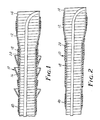
- FIG. 1 illustrates a termination assembly, generally indicated as 10.
- the assembly 10 is a prestretched tubular sleeve 12 supported in the stretched condition by an easily removable core 14.
- the assembly 10 is typically designated a "PST", which stands for pre-stretched tube.
- PST pre-stretched tube.
- the core 14 is a one-piece rigid spiral core having interconnected adjacent coils in a closed helical configuration, as described in U.S. patent no. 3,515,798.
- the outer sleeve 12 is preferably silicone rubber, although a wide variety of materials may be used so long as they possess the required arc and track resistance, ultraviolet resistance and ability to stretch and recover substantially their original dimensions when the core 14 is removed.
- the termination assembly of Figure 1 is primarily intended for outdoor use and so includes rain sheds 16 which increase the tracking length along the length of the sleeve 12. Space is usually more critical in indoor applications, so the rain sheds 16 are usually dispensed with in these situations, as shown in Figure 2.
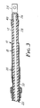
- Either termination assembly 10 is applied as shown in Figure 3 to an electrical power cable 22 which has a suitable terminating device such as the lug 24 shown crimped to the conductor 26 of the cable 22.
- the cable 22 must be prepared by removing a predetermined length of insulation 28 covering the conductor 26 and a greater predetermined length of semi-conductive shielding 30 covering the insulation 28. Cutting back the shield 30 causes a discontinuity in the electrical field surrounding the conductor 26 which results in high electrical stresses at the end of the shield 30. The high stress can cause electrical discharge to occur, which in turn may cause breakdown of the insulation 28 of the cable 22 or the termination sleeve 12.
- the present invention is intended to control these high electrical stresses to avoid these undesirable results.
- Electrical stress control in the preferred embodiment is provided in the termination 10 by the combined use of a high permittivity stress control tube 18 lining a portion of the sleeve 12, and a conformable stress control material 20 within the stress control tube 18.
- the thicknesses of the stress control tube 18 and the conformable stress control material 20, the length of the conformable stress control material 20 and the permittivity of both the stress control tube 18 and the conformable stress control material 20 are controlled to accomplish the desired stress control within the termination assembly 10.
- the high permittivity stress control tube 18 is described generally in U.S. patent number 4,363,842.
- the article taught in that patent has been modified somewhat to produce the preferred stress control tube 18 defined by the following composition: Parts by Weight Nordel 1470 (Tradename for an ethylene/propylene/diene monomer rubber commercially available from Dupont) 50 Nordel 1440 (Tradename for an ethylene/propylene/diene monomer rubber commercially available from Dupont) 50 Zinc oxide (French Process) 5.0 ARO60 Carbon Black (a N754 grade, large particle size carbon black commercially available from J.M.
- the conformable stress control material 20 is described in U.S. patent application Serial No. 08/524,390 (see WO 97/09725 A) filed on like date as parent patent application Serial No. 08/524,236 (see WO 97/09763).
- the conformable stress control material 20 is comprised of a resin component which consists of a blend of two polymeric resins; epihalohydrin polymers and insulating polymers having an electrical dissipation factor (tan ⁇ ) of less than 1.
- Epihalohydrin polymers suitable for use are the elastomeric polymers of an epihalohydrin in homopolymer or copolymer form. Such polymers are prepared by polymerization of the monomeric material in mass or in solution with organometallic catalysts, and may be homopolymers, copolymers, terpolymers, etc.
- homopolymers examples include epichlorohydrin, or epibromohydrin; useful copolymers include copolymers of epihalohydrins with alkylene oxides, and copolymers with epoxides, e.g., propylene oxide, ethylene oxide, butene oxide, and epoxy ethers such as ethylglycidyl ether, allylglycidyl ether and the like. Such polymers are available from Zeon Chemicals, Inc.
- Preferred epihalohydrin polymers include copolymers with alkylene oxides, particularly ethylene and propylene oxides.
- the resin component also contains an insulating polymer having a tan ⁇ of less than one.
- Useful polymers include silicone, EPM or EPDM and hydrocarbon rubbers.
- Useful silicones include silicones which are fluid at room temperature and gum silicones; gum silicones are preferred for easy compounding and processability; most preferred are those gum silicones having a durometer of about 30.
- silicone elastomers include those fluid silicones available as Dow Corning DC 10,000, and the like, and gum silicones available as Elastosil® R300/30 from Wacker Silicones Corporation, and Silastic® GP31 from Dow Corning, and the like.
- This formulation produces a non-tacky, conformable stress control material 20 comprising:
- Preferred non-tacky electrical stress control materials comprise:
- the highest electrical stress of a prepared cable 22 occurs at the cut back end of the semi-conductive insulation shield 30.
- the present invention coordinates two components held to specific relative geometries based on their permittivities to provide stress control.
- the inner conformable stress control material 20 is positioned to extend in both directions from the cut edge of the shield 30 and should have a thickness sufficient to fill the radial step from the outer surface of the cable insulation 28 to the outer surface of the shield 30.
- the stress control tube 18 advantageously covers the conformable stress control material 20 and extends beyond the conformable stress control material 20 in both directions from the edge of the shield 30.
- the maximum internal electrical stress at the cable insulation 28 is primarily affected by the permittivity of the conformable stress control material 30.
- the permittivity of the conformable stress control material must be high enough to prevent its breakdown at the maximum power frequency voltage withstand required for the cable and its attached termination to achieve the required voltage rating in accordance with industry standard tests.
- the breakdown strengths for the conformable stress control materials tested were about 11800 V/mm.
- the permittivity of the conformable stress control material should be at least about 16. Since the most common voltage range is 15 to 69 kV, the preferred value for the permittivity is greater than 22, and most preferably is greater than 25.
- This relationship assumes a thickness of the termination sleeve 12 of about 2 mm. This thickness being the thinnest which will withstand voltage breakdown through the sleeve 12 to conserve material. Increased thickness of the sleeve 12 will also reduce stress at the outer surface of the sleeve 12.
- the maximum permissible external stresses, S, must be below a level which would cause electrical breakdown of air during impulse conditions.
- the impulse breakdown strength for terminations was found to be between about 3000 and 9200 Volts/mm.
- the preferred embodiment should maintain stress at required impulse levels at about 3150 Volts/mm. This factor allows a maximum quantity for B to be calculated.
- the thickness of the conformable stress control material 20 be at least 1 mm and most preferably between 2 and 3 mm to ensure that the material 20 completely fills the step at the cut end of the shield 30.
- the length of the conformable material 20 is at least 10 mm and preferably 25 to 50 mm along the cable insulation 28, in addition it is preferred that the conformable material extend about 10 mm on top of the cable shield 30 to ensure intimate contact with the shield 30, although this extension is not necessary so long as there is contact between the conformable stress control material 20 and the cable shield 30.
- the stress control tube 18 is preferably about 60 mm long, it being found that a longer length has no further effect for tube 18 permitivities of less than 50.
- the stress control tube 18 should not extend beyond the cut end of the cable insulation 28 and should not extend beyond the cut-back point of any further layers (for example, any metal shielding) above the cable shield 30.
- the thickness of the tube 18 is preferably at least 1 mm and most preferably between 2 and 3 mm.
- Manipulation of these various parameters permits one to predict, for example, the necessary permittivity of the stress control tube 18 to be determined based on dimensions given or allows one to predict the dimensions the two stress control components must assume for given permittivities of the materials.
- the use of the two component stress control system described above so greatly improves stress control over prior art approaches that the stress adjacent the lug becomes the area of highest stress.
- the stress adjacent the cut cable shield can be approximately 100 times as great as the stress at the lug end of the termination, perhaps 1000 kV/cm at the cut shield and 10 kV/cm at the lug end.
- the two component stress control system is effective in reducing the stress adjacent the cut shield to the point where the surface stress at the lug end is the predominate stress on the surface of the termination.
- Prior art terminations utilize a silicone sealing compound 40 adjacent the lug end of the termination to remove air voids around the lug and to provide a weather tight seal. It has been discovered that by replacing the silicone sealing compound 40 with the stress control compound disclosed herein, electrical stress adjacent the lug is significantly reduced.
- this embodiment of the inventive termination having a first region of stress control material 20 (in contact with the cut end of shield 30) and a second region of stress control material 21 (in contact with the cut end of the cable insulation 28 and lug) exhibits improved AC withstand performance and impulse withstand performance.
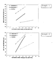
- Graphs 1 and 2 compare performance of a tubular termination without stress control compound (Control), with conformable stress control compound adjacent the cut end of the cable shield 30 only (Embodiment 1), and with conformable stress control compound adjacent to both the cut end of the shield 30 and the cut end of the insulation 28 and lug (Embodiment 2).
- a stress control tube is used in all examples.
- the graphs illustrate performance of tubular terminations, similar relative performance improvements would be expected with skirted terminations.
- first region of stress control compound 20 adjacent the cut end of shield 30 produces superior performance to a termination without stress control compound
- second region of stress control compound 21 adjacent the cut end of insulation 28 and lug results in a termination which exhibits even better performance for a given termination length. Accordingly, terminations may be made shorter for a given performance level.
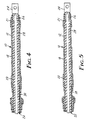
- the polymeric stress control tube 18, which extends between the first and second regions of stress controlling material 20, 21, may be disposed over only one or both of the regions of conformable stress control material 20, 21.
- Figure 4 shows the stress control tube 18 extending between the first and second regions of stress control material 20, 21, while Figure 5 shows the stress control tube 18 extending only over the first region of stress control material 20.
- the first and second regions of stress controlling material 20, 21 may also be extended through the termination such that the first and second regions 20, 21 contact each other (not shown).
- the conformable stress control material is preferably comprised of a blend of epihalohydrin polymers and insulating polymers having an electrical dissipation factor of less than 1, and has a permittivity ⁇ p of greater than 10, preferably at least about 16 and more preferably between about 20 and 50.
- the use of the stress control system described above consisting of the two regions of conformable stress control material greatly improves stress control over approaches in the past, and so permits either improved electrical performance for a give termination length or allows a reduction in termination length at a given performance level. Since all components may be loaded on the core 14 of the termination assembly 10, application of the components is a one-step process and so is very economical and convenient.
Description
- The present invention relates to electrical stress control and more particularly to a method and an arrangement to control electrical stress in a region of high electric field strength associated with high voltage electrical equipment.
- It is well known to employ stress control means to control electrical stress in a region of high electrical field strength due to a shield discontinuity in high voltage cable or electrical equipment, for example, electrical bushings, and joints or terminations of high voltage cables. Such stress control means typically comprise stress cones and tapes or tubular articles of semi-conductive stress control material. This invention is directed to stress control means comprising high permittivity stress control material and provides improved corona discharge extinction, power frequency voltage withstand and impulse voltage withstand performance over prior art arrangements using such stress control means. For purposes of illustration, this invention is described primarily as it applies to a termination of a high voltage cable. The invention can be applied, however, to other electrical cable or equipment where stress control is desired.
- A typical high voltage cable includes an inner conductor surrounded by a conductor shield which is, in turn, surrounded by an insulating material that is surrounded by an outer electrically semi-conductive shield, in some instances, and metal shield. In terminating such a cable, it is customary to remove or cut back each successive layer of the cable to expose the layer below. Cutting back the electrically semi-conductive shield causes a discontinuity in the electric field resulting in high electric stress at the end of the shield. The high electrical stress can cause electrical discharges to occur, which in turn tend to cause breakdown of the insulation of the cable. The high electrical stress can be controlled by electrical stress control means.
- High-voltage alternating current cable terminations are generally tested in the U.S. under the IEEE standard test procedure Std. 48-1990. This procedure sets forth, inter alia, design tests to be performed by the manufacturer to obtain information on the performance of a high voltage cable termination.
- The design tests of the IEEE procedure that are particularly useful in determining the effectiveness of a termination which includes a stress control arrangement include the "Partial Discharge (Corona) Extinction Voltage Test," the "Power Frequency Voltage Withstand Test" and the "Lightning Impulse Voltage Withstand Test." In the discharge extinction voltage test, electrical discharge in the termination is measured at specific applied voltages and has to be below specific values. Also the voltage at which the discharge extinguishes is measured and has to be above specific values. In the power frequency voltage withstand tests the specified voltage is applied to the cable and should be withstood without flashover or other dielectric breakdown. In the impulse voltage withstand test, impulses of specific value and waveform are applied to the cable and should be withstood without flashover or other dielectric breakdown. The voltage at which flashover occurs should be above specific values. The discharge, power frequency voltage and impulse voltage performance of the termination should meet the requirements set forth in the IEEE Standard Test procedures STD 48-1990.
- DE-G 82 36 151 U1 discloses a termination for an electrical power cable including an inner conductor, electrical insulation and semi-conductive shield. The termination comprises a tubular stress control element which may be heat-shrunk over the cable and is therefore conformable. The element has one end overlapping the shield and extends along the exposed cable insulation, with its other end surrounding the exposed conductor. The element, which has a permittivity greater than 50, thus constitutes a first region in contact with the cut end of the cable shield and extending along the cable insulation, and a second region disposed in contact with the cut end of the cable insulation, the two regions being in contact. A polymeric electrically insulating layer, which may consist of another heat-shrunk tube is disposed over the tubular element and extends from a first end of the termination to a second end of the termination.
- EP-A-0 147 978 discloses a similar arrangement with a stress control layer covered by an insulating layer.
- FR-A-2 371 804 discloses a termination for an electrical power cable which comprises a first region of conformable stress control material of high permittivity in contact with a cut end of the semi-conductive cable shield and extending along the cable insulation. The coating may be held in place by a mesh tape of polyethylene or the like. A second material is disposed in a region in contact with a cut end of the cable insulation. However, this second material is a semi-conductive tape while another tape extends between the two regions to provide environmental protection for the cable end.
- The use of stress control material in high voltage cable terminations does not always produce terminations that meet the impulse performance requirements of the IEEE test procedures. In order to meet this requirement the stress control arrangement may be augmented by the use of rain sheds. While sheds are typically employed with outdoor terminations for other purposes, they are not generally employed when the cable termination is installed indoors. Since the use of sheds adds to the cost of the termination and requires additional space around the cable, it is desirable to be able to dispense with the use of the sheds yet still meet the desired impulse performance.
- The present invention, provides a novel arrangement that significantly improves the termination's discharge, power frequency voltage and impulse voltage performance with or without the use of sheds. While the present invention is primarily described in connection with a termination of a cable, it is suitable for employment with high voltage cable joints and other high voltage equipment including electrical bushings and feedthroughs.
- The present invention includes termination for an electrical power cable including an inner conductor, electrical insulation surrounding the conductor and a semi-conductive shield surrounding the insulation, wherein the shield is removed to a predetermined length and the insulation is removed to a lesser predetermined length to expose the conductor, the termination comprising:
- a first region of permittivity greater than 10 conformable stress control material in contact with a cut end of the cable shield and extending along the cable insulation;
- a second region of permittivity greater than 10 conformable stress control material disposed in contact with a cut end of the cable insulation;
- a polymeric electrically insulating layer extending from a first end of the termination to a second end of the termination, the electrically insulating layer disposed over said first and second regions of permittivity greater than 10 conformable stress control material; and
- a polymeric stress control tube extending between said first and second regions of conformable stress control material.
-
- The present invention will be described with respect to the accompanying drawings, wherein like numbers refer to like parts in the several views, and wherein:
- Figure 1 is a cross-sectional view of a stress control termination sleeve with rain sheds;
- Figure 2 is a cross-sectional view of a stress control termination sleeve without rain sheds; and
- Figure 3 is a cross-sectional view of the stress control termination sleeve of the present invention as applied to an electrical power cable.
-
Graphs - Figure 4 is a cross-sectional view of an alternate embodiment of the stress control termination sleeve of the present invention as applied to an electrical power cable.
- Figure 5 is a cross-sectional view of yet another alternate embodiment of the stress control termination sleeve of the present invention as applied to an electrical power cable.
-
- Figure 1 illustrates a termination assembly, generally indicated as 10. The
assembly 10 is a prestretchedtubular sleeve 12 supported in the stretched condition by an easilyremovable core 14. Theassembly 10 is typically designated a "PST", which stands for pre-stretched tube. Such anassembly 10 is taught in U.S. patent no. 3,515,798. Preferably thecore 14 is a one-piece rigid spiral core having interconnected adjacent coils in a closed helical configuration, as described in U.S. patent no. 3,515,798. Theouter sleeve 12 is preferably silicone rubber, although a wide variety of materials may be used so long as they possess the required arc and track resistance, ultraviolet resistance and ability to stretch and recover substantially their original dimensions when thecore 14 is removed. - The termination assembly of Figure 1 is primarily intended for outdoor use and so includes
rain sheds 16 which increase the tracking length along the length of thesleeve 12. Space is usually more critical in indoor applications, so therain sheds 16 are usually dispensed with in these situations, as shown in Figure 2. Eithertermination assembly 10 is applied as shown in Figure 3 to anelectrical power cable 22 which has a suitable terminating device such as thelug 24 shown crimped to theconductor 26 of thecable 22. - To apply the
lug 24 and thus terminate thecable 22, thecable 22 must be prepared by removing a predetermined length ofinsulation 28 covering theconductor 26 and a greater predetermined length ofsemi-conductive shielding 30 covering theinsulation 28. Cutting back theshield 30 causes a discontinuity in the electrical field surrounding theconductor 26 which results in high electrical stresses at the end of theshield 30. The high stress can cause electrical discharge to occur, which in turn may cause breakdown of theinsulation 28 of thecable 22 or thetermination sleeve 12. The present invention is intended to control these high electrical stresses to avoid these undesirable results. - Electrical stress control in the preferred embodiment is provided in the
termination 10 by the combined use of a high permittivitystress control tube 18 lining a portion of thesleeve 12, and a conformablestress control material 20 within thestress control tube 18. The thicknesses of thestress control tube 18 and the conformablestress control material 20, the length of the conformablestress control material 20 and the permittivity of both thestress control tube 18 and the conformablestress control material 20 are controlled to accomplish the desired stress control within thetermination assembly 10. - The high permittivity
stress control tube 18 is described generally in U.S. patent number 4,363,842. - The article taught in that patent has been modified somewhat to produce the preferred
stress control tube 18 defined by the following composition:Parts by Weight Nordel 1470 (Tradename for an ethylene/propylene/diene monomer rubber commercially available from Dupont) 50 Nordel 1440 (Tradename for an ethylene/propylene/diene monomer rubber commercially available from Dupont) 50 Zinc oxide (French Process) 5.0 ARO60 Carbon Black (a N754 grade, large particle size carbon black commercially available from J.M. Huber) 71.35 4X Mineralite Mica (commercially available from Thompson Hayward Chemical) 20 D-148 (Tradename for a processing aid commercially available from Ventron 2.0 Struktol WB-16 (Tradename for a mixture of fatty acid soap, predominantly calcium, available from Struktol Company) 2.0 EF (A-172) D-50 (Tradename for a vinyl silane coupling agent predispersed on a hydrocarbon wax commercially available from Elastochem) 1.0 Sunpar 2280 (Tradename for a paraffinic process oil commercially available from the Sun Company) 9.8 Plasthall DOZ (Tradename for Di-2-Ethylhexyl Azelate commercially available from C.P. Hall Co.) 13.3 Plasthall DIDG (Tradename for Diisodecyl Glutarate commercially available from C.P. Hall Co.) 13.3 Silvex 113-20-C (Tradename for a mineral oil treated aluminum flake of 22 micron average particle diameter commercially available from Silberline Manufacturing) 8.5 Drimix SR-297-75E (Tradename for 1,3 butylene dimethacrylate dispersion commercially available from Kenrich Petrochemicals) 7.0 E (VC) D-40 (Trade name for a difunctional peroxide dispersion commercially available from Elastochem) 4.5 - The conformable
stress control material 20 is described in U.S. patent application Serial No. 08/524,390 (see WO 97/09725 A) filed on like date as parent patent application Serial No. 08/524,236 (see WO 97/09763). The conformablestress control material 20 is comprised of a resin component which consists of a blend of two polymeric resins; epihalohydrin polymers and insulating polymers having an electrical dissipation factor (tan δ) of less than 1. - Epihalohydrin polymers suitable for use are the elastomeric polymers of an epihalohydrin in homopolymer or copolymer form. Such polymers are prepared by polymerization of the monomeric material in mass or in solution with organometallic catalysts, and may be homopolymers, copolymers, terpolymers, etc. Examples of homopolymers include epichlorohydrin, or epibromohydrin; useful copolymers include copolymers of epihalohydrins with alkylene oxides, and copolymers with epoxides, e.g., propylene oxide, ethylene oxide, butene oxide, and epoxy ethers such as ethylglycidyl ether, allylglycidyl ether and the like. Such polymers are available from Zeon Chemicals, Inc.
- Preferred epihalohydrin polymers include copolymers with alkylene oxides, particularly ethylene and propylene oxides.
- The resin component also contains an insulating polymer having a tan δ of less than one. Useful polymers include silicone, EPM or EPDM and hydrocarbon rubbers. Useful silicones include silicones which are fluid at room temperature and gum silicones; gum silicones are preferred for easy compounding and processability; most preferred are those gum silicones having a durometer of about 30.
- Commercially available silicone elastomers include those fluid silicones available as Dow Corning DC 10,000, and the like, and gum silicones available as Elastosil® R300/30 from Wacker Silicones Corporation, and Silastic® GP31 from Dow Corning, and the like.
- This formulation produces a non-tacky, conformable
stress control material 20 comprising: - a) about 100 parts of a resin component
containing
- 1) from about 20% to about 80% of an epihalohydrin polymer, and
- 2) correspondingly, from about 80% to about 20% of an insulating polymer having a tan δ of less than one,
- b) from about 8 to about 200 parts of a filler selected from the group consisting of barium titanate and hydrated aluminum silicate, and
- c) from 0 to 30 parts of a plasticizer.
-
- Preferred non-tacky electrical stress control materials comprise:
- a) about 100 parts of a resin component
containing
- 1) from about 20% to about 80% of an epihalohydrin polymer, and
- 2) correspondingly, from about 80% to about 20% of a silicone polymer having a tan δ of less than one,
- b) from about 8 to about 200 parts barium titanate, and
- c) from 0 to 30 parts of a plasticizer.
-
- As stated earlier, the highest electrical stress of a
prepared cable 22 occurs at the cut back end of thesemi-conductive insulation shield 30. The present invention coordinates two components held to specific relative geometries based on their permittivities to provide stress control. - The inner conformable
stress control material 20 is positioned to extend in both directions from the cut edge of theshield 30 and should have a thickness sufficient to fill the radial step from the outer surface of thecable insulation 28 to the outer surface of theshield 30. Thestress control tube 18 advantageously covers the conformablestress control material 20 and extends beyond the conformablestress control material 20 in both directions from the edge of theshield 30. - The maximum internal electrical stress at the
cable insulation 28 is primarily affected by the permittivity of the conformablestress control material 30. The relationship to predict the maximum stress is: - A = 1.69 - 1.63 x 10⁻² εp;
- V is the applied voltage;
- R is the outside radius of the cable insulation;
- r is the inside radius of the cable insulation; and
- εp is the permittivity of the conformable stress control material.
-
- The permittivity of the conformable stress control material must be high enough to prevent its breakdown at the maximum power frequency voltage withstand required for the cable and its attached termination to achieve the required voltage rating in accordance with industry standard tests. The breakdown strengths for the conformable stress control materials tested were about 11800 V/mm. The minimum values for the permittivity of the conformable stress control material at selected voltage levels are shown in the table below:
Voltage Class (kV) Power Frequency Voltage Withstand (kV for 1 minute) V/ (R ln
(R/r))MAX
for 2500 MCM (V/mm)εp(min)
for
VBD=11800 V/mm5.0 25 10450 34 8.7 35 11320 40 15 50 8365 17 25 65 8735 21 28 70 8665 20 34.5 90 8820 22 46 120 8810 21 69 175 8245 16 - As can be seen, the permittivity of the conformable stress control material should be at least about 16. Since the most common voltage range is 15 to 69 kV, the preferred value for the permittivity is greater than 22, and most preferably is greater than 25.
- The maximum electrical stress along the outer surface of the
termination sleeve 12 adjacent to either the end of thecable shield 30 or the end of thestress controlling compound 20 is affected by many parameters. The relationship to predict this maximum stress is:
B = 0.585 + 1.76 x 10⁻³ εp - 2.43 x 10⁻³ εt
+ 7.32 x 10⁻⁵ lp - 4.45 x 10⁻² tt
- 3.39 x 10⁻² tp - 4.45 x 10⁻⁵ εp lp
where: - εp is the conformable stress control material's permittivity;
- εt is the stress control tube's permittivity;
- lp is the length of the conformable stress control material over the cable insulation in millimeters;
- tt is the thickness of the stress control tube in millimeters; and
- tp is the thickness of the conformable stress control material in millimeters.
-
- This relationship assumes a thickness of the
termination sleeve 12 of about 2 mm. This thickness being the thinnest which will withstand voltage breakdown through thesleeve 12 to conserve material. Increased thickness of thesleeve 12 will also reduce stress at the outer surface of thesleeve 12. - The maximum permissible external stresses, S, must be below a level which would cause electrical breakdown of air during impulse conditions. The impulse breakdown strength for terminations was found to be between about 3000 and 9200 Volts/mm. The preferred embodiment should maintain stress at required impulse levels at about 3150 Volts/mm. This factor allows a maximum quantity for B to be calculated. The maximum permissible values for B at Voltages of interest are listed in the table below:
Voltage Class (kV) Lightning Impulse BIL (kV) V/(R In (R/r))MAX for 2500 MCM (V/mm) B(MAX) for VBD=9200 V/mm 5.0 75 800 .292 8.7 95 780 .300 15 110 465 .499 25 150 510 .456 28 175 550 .423 34.5 200 500 .470 46 250 465 .502 69 350 420 .558 - From the relationship for B given above it can be seen that increases in the permittivity of the conformable
stress control material 20 and the length of the conformablestress control material 20 tend to increase the stress at the outer surface of thesleeve 12, although this is offset somewhat by the last term of the relationship for B, wherein it can be seen that the product of the permittivity and length of the conformablestress control material 20 tends to decrease this stress. Increases in the permittivity and thickness of thestress control tube 18 both tend to decrease the stress at the outer surface of thesleeve 12, and strongly so. As stated above, increased thickness of thetermination sleeve 12 will also reduce the stress at the outer surface of thesleeve 12. However, this thickness is maintained at the minimum required to prevent breakdown of thesleeve 12 itself, approximately 2 mm, since the silicone from which thesleeve 12 is made is relatively expensive. - In practice, it is preferred that the thickness of the conformable
stress control material 20 be at least 1 mm and most preferably between 2 and 3 mm to ensure that the material 20 completely fills the step at the cut end of theshield 30. The length of theconformable material 20 is at least 10 mm and preferably 25 to 50 mm along thecable insulation 28, in addition it is preferred that the conformable material extend about 10 mm on top of thecable shield 30 to ensure intimate contact with theshield 30, although this extension is not necessary so long as there is contact between the conformablestress control material 20 and thecable shield 30. - If stress controlling compound is positioned only adjacent the cut end of the
cable shield 30, thestress control tube 18 is preferably about 60 mm long, it being found that a longer length has no further effect fortube 18 permitivities of less than 50. To avoid limiting the range of cable sizes with which the stress control termination can be used, thestress control tube 18 should not extend beyond the cut end of thecable insulation 28 and should not extend beyond the cut-back point of any further layers (for example, any metal shielding) above thecable shield 30. The thickness of thetube 18 is preferably at least 1 mm and most preferably between 2 and 3 mm. - Manipulation of these various parameters permits one to predict, for example, the necessary permittivity of the
stress control tube 18 to be determined based on dimensions given or allows one to predict the dimensions the two stress control components must assume for given permittivities of the materials. - The use of the two component stress control system described above consisting of the conformable
stress control material 20 and thestress control tube 18 greatly improves stress control over approaches in the past, and so permits either improved electrical performance for a give termination length or allows a reduction in termination length (about 40% of prior devices) at a given performance level. Of course, these advantages may be combined to produce a somewhat shorter termination with improved electrical performance. Since all components may be loaded on thecore 14 of thetermination assembly 10, application of the components is a one-step process and so is very economical and convenient. - The use of the two component stress control system described above (having conformable stress control material in contact with the end of the cable shield and extending along the cable insulation, and then covered by a polymeric stress control tube) so greatly improves stress control over prior art approaches that the stress adjacent the lug becomes the area of highest stress. For example, in a termination without stress control the stress adjacent the cut cable shield can be approximately 100 times as great as the stress at the lug end of the termination, perhaps 1000 kV/cm at the cut shield and 10 kV/cm at the lug end. The two component stress control system is effective in reducing the stress adjacent the cut shield to the point where the surface stress at the lug end is the predominate stress on the surface of the termination.
- Until the introduction of the two component stress control system, there was no interest in addressing stress control at the lug end of the termination, because the stress adjacent the lug was small compared to the stress adjacent the cut shield. However, the large reduction in stress adjacent the cut shield allows stress control adjacent the lug to be addressed. Stress control adjacent the lug becomes important because the shorter termination lengths which are possible with the two component stress control system cause electrical stresses in the vicinity of the lug to rise to a level which may be significant. (It should be noted that the level of stress near the lug is still low when compared to the level of stress which existed in the termination prior to the introduction of the two component stress control system disclosed above).
- Prior art terminations, as well as the termination shown in Figures 1-3, utilize a
silicone sealing compound 40 adjacent the lug end of the termination to remove air voids around the lug and to provide a weather tight seal. It has been discovered that by replacing thesilicone sealing compound 40 with the stress control compound disclosed herein, electrical stress adjacent the lug is significantly reduced. In particular, this embodiment of the inventive termination having a first region of stress control material 20 (in contact with the cut end of shield 30) and a second region of stress control material 21 (in contact with the cut end of thecable insulation 28 and lug) exhibits improved AC withstand performance and impulse withstand performance. - The levels of improved performance exhibited by the first and second embodiments of the inventive terminations are illustrated in
Graphs -
Graphs cable shield 30 only (Embodiment 1), and with conformable stress control compound adjacent to both the cut end of theshield 30 and the cut end of theinsulation 28 and lug (Embodiment 2). A stress control tube is used in all examples. Although the graphs illustrate performance of tubular terminations, similar relative performance improvements would be expected with skirted terminations. - As can be seen from
Graphs stress control compound 20 adjacent the cut end ofshield 30 produces superior performance to a termination without stress control compound, and use of second region ofstress control compound 21 adjacent the cut end ofinsulation 28 and lug results in a termination which exhibits even better performance for a given termination length.
Accordingly, terminations may be made shorter for a given performance level. - It will be recognized that multiple variations of the inventive termination are possible, depending upon the particular application of the termination. In particular, the polymeric
stress control tube 18, which extends between the first and second regions ofstress controlling material stress control material stress control tube 18 extending between the first and second regions ofstress control material stress control tube 18 extending only over the first region ofstress control material 20. The first and second regions ofstress controlling material second regions - As described above, the conformable stress control material is preferably comprised of a blend of epihalohydrin polymers and insulating polymers having an electrical dissipation factor of less than 1, and has a permittivity εp of greater than 10, preferably at least about 16 and more preferably between about 20 and 50.
- The use of the stress control system described above consisting of the two regions of conformable stress control material greatly improves stress control over approaches in the past, and so permits either improved electrical performance for a give termination length or allows a reduction in termination length at a given performance level. Since all components may be loaded on the
core 14 of thetermination assembly 10, application of the components is a one-step process and so is very economical and convenient.
Claims (9)
- A termination for an electrical power cable including an inner conductor (26), electrical insulation (28) surrounding the conductor and a semi-conductive shield (30) surrounding the insulation, wherein the shield is removed to a predetermined length and the insulation is removed to a lesser predetermined length to expose the conductor, the termination comprising:a first region (20) of permittivity greater than 10 conformable stress control material in contact with a cut end of the cable shield and extending along the cable insulation;a second region (21) of permittivity greater than 10 conformable stress control material disposed in contact with a cut end of the cable insulation;a polymeric electrically insulating layer (12) extending from a first end of the termination to a second end of the termination, the electrically insulating layer disposed over said first and second regions of permittivity greater than 10 conformable stress control material; anda polymeric stress control tube (18) extending between said first (20) and second (21) regions of conformable stress control material.
- The termination of claim 1, wherein
the polymeric stress control tube (18) is disposed over said first region (20) of conformable stress control material. - The termination of claim 1, wherein
the polymeric stress control tube (18) is disposed over said second region (21) of conformable stress control material. - The termination of claim 1, wherein the first and second regions of conformable stress control material contact each other.
- The termination of claim 1, wherein the permittivity εp of said conformable stress control material is at least about 16.
- The termination of claim 1, wherein the permittivity εp of said conformable stress control material is between about 20 and 50.
- The termination of claim 1, wherein the length of said first region of conformable stress control material, the thickness of said first region of stress control material and the thickness of said stress control tube are defined by the following equation, wherein B is the parameter used to calculate the maximum external electrical stress on the outer surface of the insulating layer adjacent the cut end of the cable shield, and whereinεp is said conformable stress control material's permittivity;εt is said stress control tube's permittivity;lp is the length of said conformable stress control material over said cable insulation in millimeters;tt is the thickness of said stress control tube in millimeters; andtp is the thickness of said conformable stress control material in millimeters.
- The termination of claim 7, wherein B is less than about 0.56.
- The termination of claim 1, wherein the conformable stress control material is comprised of a blend of epihalohydrin polymers and insulating polymers having an electrical dissipation factor of less than 1.
Applications Claiming Priority (3)
| Application Number | Priority Date | Filing Date | Title |
|---|---|---|---|
| US763390 | 1991-09-20 | ||
| US08/763,390 US6340794B1 (en) | 1995-09-06 | 1996-12-16 | Stress control for termination of a high voltage cable |
| PCT/US1997/004156 WO1998027631A1 (en) | 1996-12-16 | 1997-03-10 | Stress control for termination of a high voltage cable |
Publications (2)
| Publication Number | Publication Date |
|---|---|
| EP0944944A1 EP0944944A1 (en) | 1999-09-29 |
| EP0944944B1 true EP0944944B1 (en) | 2001-08-29 |
Family
ID=25067726
Family Applications (1)
| Application Number | Title | Priority Date | Filing Date |
|---|---|---|---|
| EP97915114A Expired - Lifetime EP0944944B1 (en) | 1996-12-16 | 1997-03-10 | Stress control for termination of a high voltage cable |
Country Status (10)
| Country | Link |
|---|---|
| US (1) | US6340794B1 (en) |
| EP (1) | EP0944944B1 (en) |
| JP (1) | JP4347909B2 (en) |
| AU (1) | AU2213897A (en) |
| BR (1) | BR9713938B1 (en) |
| CA (1) | CA2272898C (en) |
| DE (1) | DE69706435T2 (en) |
| ES (1) | ES2159856T3 (en) |
| TW (1) | TW348336B (en) |
| WO (1) | WO1998027631A1 (en) |
Cited By (1)
| Publication number | Priority date | Publication date | Assignee | Title |
|---|---|---|---|---|
| WO2014057381A1 (en) | 2012-10-09 | 2014-04-17 | Tyco Electronics (Shanghai) Co. Ltd. | Cold shrinkable termination for an electric power cable |
Families Citing this family (23)
| Publication number | Priority date | Publication date | Assignee | Title |
|---|---|---|---|---|
| US6015629A (en) * | 1995-09-06 | 2000-01-18 | 3M Innovative Properties Company | Stress control for termination of a high voltage cable |
| ITAV20010004A1 (en) * | 2001-03-28 | 2002-09-28 | Elcon Srl | "INDUSTRIAL PRODUCTION METHOD OF SELF-STRINGING JOINTS AND TERMINALS WITH SEVERAL TECHNICAL WALLS, WITHOUT THE ADOPTION OF CO-MOLDING AND CO |
| DE10228665B4 (en) * | 2001-10-30 | 2004-06-03 | Dehn + Söhne Gmbh + Co. Kg | Biltzstromableiteinrichtung |
| US6905356B2 (en) * | 2002-05-16 | 2005-06-14 | Homac Mfg. Company | Electrical connector including thermoplastic elastomer material and associated methods |
| US6796820B2 (en) * | 2002-05-16 | 2004-09-28 | Homac Mfg. Company | Electrical connector including cold shrink core and thermoplastic elastomer material and associated methods |
| US7104823B2 (en) * | 2002-05-16 | 2006-09-12 | Homac Mfg. Company | Enhanced separable connector with thermoplastic member and related methods |
| US6790063B2 (en) | 2002-05-16 | 2004-09-14 | Homac Mfg. Company | Electrical connector including split shield monitor point and associated methods |
| US6830475B2 (en) * | 2002-05-16 | 2004-12-14 | Homac Mfg. Company | Electrical connector with visual seating indicator and associated methods |
| US7104822B2 (en) * | 2002-05-16 | 2006-09-12 | Homac Mfg. Company | Electrical connector including silicone elastomeric material and associated methods |
| US6811418B2 (en) * | 2002-05-16 | 2004-11-02 | Homac Mfg. Company | Electrical connector with anti-flashover configuration and associated methods |
| WO2004004088A1 (en) * | 2002-06-26 | 2004-01-08 | Pirelli & C. S.P.A. | Method and arrangement for a termination of an electrical cable |
| US6979707B2 (en) * | 2003-03-17 | 2005-12-27 | Fujikura Ltd. | High-permittivity rubber compounds and power cable members |
| US20060081393A1 (en) * | 2004-10-14 | 2006-04-20 | Anthony Suzanne T | Modular skirt systems and method of using |
| US7351908B2 (en) * | 2006-08-18 | 2008-04-01 | 3M Innovative Properties Company | Electrical power cable adaptor and method of use |
| US7973241B2 (en) * | 2007-09-10 | 2011-07-05 | 3M Innovative Properties Company | Pressure restraining enclosure for cables |
| US20110011484A1 (en) * | 2009-07-16 | 2011-01-20 | 3M Innovative Properties Company | Cold shrink article |
| PL2608338T3 (en) * | 2011-12-21 | 2014-04-30 | 3M Innovative Properties Co | Terminal connection device for a power cable |
| DE102012212205A1 (en) * | 2012-07-12 | 2014-05-15 | Tyco Electronics Raychem Gmbh | Container for an electrical or optical conductor |
| US8774587B1 (en) | 2013-01-26 | 2014-07-08 | Optisense Network, Llc | Stress control structure for optical fibers in a high voltage environment |
| CN104956448A (en) | 2013-02-04 | 2015-09-30 | 3M创新有限公司 | Insulating composition, insulating article, preparation method and electrical cable accessory thereof |
| US20140287175A1 (en) * | 2013-03-19 | 2014-09-25 | Shawcor Ltd. | Products for stress control in electrical power cables |
| US9347973B2 (en) | 2013-05-15 | 2016-05-24 | Gridview Optical Solutions, Llc | Stress control assembly and methods of making the same |
| US10819097B2 (en) * | 2017-03-10 | 2020-10-27 | 3M Innovative Properties Company | Cover assembly with hybrid core structure |
Family Cites Families (23)
| Publication number | Priority date | Publication date | Assignee | Title |
|---|---|---|---|---|
| US2373843A (en) | 1942-10-28 | 1945-04-17 | G & W Electric Speciality Co | Insulated electrical conductor terminal structure |
| US3356788A (en) * | 1963-11-19 | 1967-12-05 | Aluminum Co Of America | Stress relief cones for high voltage, shielded conductors |
| US3377420A (en) | 1965-04-16 | 1968-04-09 | Elastic Stop Nut Corp | Device for terminating outdoor electric cables |
| US3539703A (en) | 1968-10-23 | 1970-11-10 | High Voltage Power Corp | High voltage termination apparatus for high voltage cables and pipetype transmission lines |
| US3515798A (en) | 1968-12-06 | 1970-06-02 | Minnesota Mining & Mfg | Elastic cover and removable cone assembly |
| US3846578A (en) * | 1972-03-22 | 1974-11-05 | Phelps Dodge Ind Inc | Splice for electric cables |
| GB1470501A (en) | 1973-03-20 | 1977-04-14 | Raychem Ltd | Polymer compositions for electrical use |
| US3828115A (en) | 1973-07-27 | 1974-08-06 | Kerite Co | High voltage cable having high sic insulation layer between low sic insulation layers and terminal construction thereof |
| GB1526397A (en) | 1974-10-08 | 1978-09-27 | Raychem Ltd | Heat-recoverable article suitable for high voltage use |
| US4187389A (en) | 1975-04-11 | 1980-02-05 | Sola Basic Industries, Inc. | Shielded electrical conductor terminations and methods of making same |
| GB1604612A (en) | 1976-10-29 | 1981-12-09 | Raychem Ltd | Epihalohydrin polymer compositions |
| FR2371804A1 (en) | 1976-11-18 | 1978-06-16 | Telecommunications Sa | Medium tension radial field electric cable with resin-contg. coating - having uniform electric field at extremity to obviate electric discharges during use |
| US4383131A (en) | 1978-09-14 | 1983-05-10 | Raychem Limited | Shielded electrical cable joints and terminations and sleeve and method for forming same |
| US4251814A (en) | 1979-09-18 | 1981-02-17 | Tektronix, Inc. | Time dot display for a digital oscilloscope |
| US4363842A (en) | 1981-03-02 | 1982-12-14 | Minnesota Mining And Manufacturing Company | Elastomeric pre-stretched tubes for providing electrical stress control |
| FR2518837B1 (en) | 1981-12-18 | 1985-08-09 | Fabrication Cables Elect Cie G | PROCESS FOR PREPARING THE END OF HIGH-VOLTAGE RADIAL FIELD ELECTRICAL CABLES AND ELECTRICAL CABLES THUS OBTAINED |
| DE8236151U1 (en) | 1982-12-23 | 1983-06-09 | Kabel- Und Lackdrahtfabriken Gmbh, 6800 Mannheim | Termination for a medium voltage cable |
| GB8303462D0 (en) | 1983-02-08 | 1983-03-16 | Raychem Gmbh | Electrical stress control |
| US4551915A (en) | 1983-04-06 | 1985-11-12 | Raychem Corporation | Method for terminating a high voltage cable |
| GB8333249D0 (en) | 1983-12-13 | 1984-01-18 | Raychem Ltd | Electrically insulating articles |
| IT1228468B (en) | 1989-01-16 | 1991-06-19 | Pirelli Cavi Spa | ELEMENT OF A DEVICE FOR MAKING AN ELECTRIC CABLES JOINT, ELECTRIC CABLES JOINT WITH IT OBTAINED AND COATING OF THE CONNECTION OF ELECTRIC CABLES CONDUCTORS FOR THAT JOINT. |
| US5171940A (en) * | 1989-10-11 | 1992-12-15 | Societa' Cavi Pirelli S.P.A. | Expanded cable joint elastic sleeves with permissible residual deformation after storage |
| US5280136A (en) | 1991-09-16 | 1994-01-18 | Amerace Corporation | Method and apparatus for terminating a shielded high voltage cable |
-
1996
- 1996-12-16 US US08/763,390 patent/US6340794B1/en not_active Expired - Lifetime
-
1997
- 1997-03-10 ES ES97915114T patent/ES2159856T3/en not_active Expired - Lifetime
- 1997-03-10 DE DE69706435T patent/DE69706435T2/en not_active Expired - Lifetime
- 1997-03-10 CA CA002272898A patent/CA2272898C/en not_active Expired - Fee Related
- 1997-03-10 AU AU22138/97A patent/AU2213897A/en not_active Abandoned
- 1997-03-10 JP JP52765698A patent/JP4347909B2/en not_active Expired - Fee Related
- 1997-03-10 WO PCT/US1997/004156 patent/WO1998027631A1/en active IP Right Grant
- 1997-03-10 BR BRPI9713938-6A patent/BR9713938B1/en not_active IP Right Cessation
- 1997-03-10 EP EP97915114A patent/EP0944944B1/en not_active Expired - Lifetime
- 1997-12-05 TW TW086118362A patent/TW348336B/en not_active IP Right Cessation
Cited By (1)
| Publication number | Priority date | Publication date | Assignee | Title |
|---|---|---|---|---|
| WO2014057381A1 (en) | 2012-10-09 | 2014-04-17 | Tyco Electronics (Shanghai) Co. Ltd. | Cold shrinkable termination for an electric power cable |
Also Published As
| Publication number | Publication date |
|---|---|
| CA2272898C (en) | 2006-05-09 |
| WO1998027631A1 (en) | 1998-06-25 |
| US6340794B1 (en) | 2002-01-22 |
| JP2001506478A (en) | 2001-05-15 |
| BR9713938A (en) | 2000-03-21 |
| AU2213897A (en) | 1998-07-15 |
| DE69706435T2 (en) | 2002-05-16 |
| EP0944944A1 (en) | 1999-09-29 |
| TW348336B (en) | 1998-12-21 |
| BR9713938B1 (en) | 2010-02-23 |
| ES2159856T3 (en) | 2001-10-16 |
| JP4347909B2 (en) | 2009-10-21 |
| DE69706435D1 (en) | 2001-10-04 |
| CA2272898A1 (en) | 1998-06-25 |
Similar Documents
| Publication | Publication Date | Title |
|---|---|---|
| EP0944944B1 (en) | Stress control for termination of a high voltage cable | |
| US6015629A (en) | Stress control for termination of a high voltage cable | |
| EP0848854B1 (en) | Epihalohydrin electrical stress controlling material | |
| EP0847610B1 (en) | Elastically recoverable silicone splice cover | |
| EP0148196B1 (en) | Electrical stress control apparatus and method | |
| EP0780949A1 (en) | Universal cable adapter, cable joint using the adapter and method of making the same | |
| EP0848865B1 (en) | Stress control for termination of a high voltage cable | |
| US20140287175A1 (en) | Products for stress control in electrical power cables | |
| CA2231233C (en) | Stress control for termination of a high voltage cable | |
| Mackevich et al. | Insulation enhancement with heat-shrinkable components. III. Shielded power cable | |
| JP3029203B2 (en) | Connections and ends of cross-linked polyethylene power cables | |
| EP0522760A1 (en) | Heat recoverable tubular stress control element | |
| CN216451143U (en) | Cable termination assembly and cable termination device | |
| JP3777958B2 (en) | Cross-linked polyethylene insulated power cable suitable for recycling | |
| JPH084633Y2 (en) | Termination of lead cable for DC withstanding voltage test | |
| JPS6123734B2 (en) | ||
| JPH11283443A (en) | Insulator | |
| JPH0477532B2 (en) |
Legal Events
| Date | Code | Title | Description |
|---|---|---|---|
| PUAI | Public reference made under article 153(3) epc to a published international application that has entered the european phase |
Free format text: ORIGINAL CODE: 0009012 |
|
| 17P | Request for examination filed |
Effective date: 19990617 |
|
| AK | Designated contracting states |
Kind code of ref document: A1 Designated state(s): DE ES FR GB IT |
|
| GRAG | Despatch of communication of intention to grant |
Free format text: ORIGINAL CODE: EPIDOS AGRA |
|
| 17Q | First examination report despatched |
Effective date: 20010108 |
|
| GRAG | Despatch of communication of intention to grant |
Free format text: ORIGINAL CODE: EPIDOS AGRA |
|
| GRAH | Despatch of communication of intention to grant a patent |
Free format text: ORIGINAL CODE: EPIDOS IGRA |
|
| GRAH | Despatch of communication of intention to grant a patent |
Free format text: ORIGINAL CODE: EPIDOS IGRA |
|
| GRAA | (expected) grant |
Free format text: ORIGINAL CODE: 0009210 |
|
| AK | Designated contracting states |
Kind code of ref document: B1 Designated state(s): DE ES FR GB IT |
|
| REF | Corresponds to: |
Ref document number: 69706435 Country of ref document: DE Date of ref document: 20011004 |
|
| REG | Reference to a national code |
Ref country code: ES Ref legal event code: FG2A Ref document number: 2159856 Country of ref document: ES Kind code of ref document: T3 |
|
| ET | Fr: translation filed | ||
| REG | Reference to a national code |
Ref country code: GB Ref legal event code: IF02 |
|
| PLBE | No opposition filed within time limit |
Free format text: ORIGINAL CODE: 0009261 |
|
| STAA | Information on the status of an ep patent application or granted ep patent |
Free format text: STATUS: NO OPPOSITION FILED WITHIN TIME LIMIT |
|
| 26N | No opposition filed | ||
| REG | Reference to a national code |
Ref country code: HK Ref legal event code: WD Ref document number: 1022997 Country of ref document: HK |
|
| REG | Reference to a national code |
Ref country code: FR Ref legal event code: PLFP Year of fee payment: 19 |
|
| PGFP | Annual fee paid to national office [announced via postgrant information from national office to epo] |
Ref country code: ES Payment date: 20150212 Year of fee payment: 19 Ref country code: DE Payment date: 20150305 Year of fee payment: 19 Ref country code: IT Payment date: 20150224 Year of fee payment: 19 |
|
| PGFP | Annual fee paid to national office [announced via postgrant information from national office to epo] |
Ref country code: GB Payment date: 20150304 Year of fee payment: 19 Ref country code: FR Payment date: 20150309 Year of fee payment: 19 |
|
| REG | Reference to a national code |
Ref country code: DE Ref legal event code: R119 Ref document number: 69706435 Country of ref document: DE |
|
| GBPC | Gb: european patent ceased through non-payment of renewal fee |
Effective date: 20160310 |
|
| REG | Reference to a national code |
Ref country code: FR Ref legal event code: ST Effective date: 20161130 |
|
| PG25 | Lapsed in a contracting state [announced via postgrant information from national office to epo] |
Ref country code: FR Free format text: LAPSE BECAUSE OF NON-PAYMENT OF DUE FEES Effective date: 20160331 Ref country code: GB Free format text: LAPSE BECAUSE OF NON-PAYMENT OF DUE FEES Effective date: 20160310 Ref country code: DE Free format text: LAPSE BECAUSE OF NON-PAYMENT OF DUE FEES Effective date: 20161001 |
|
| PG25 | Lapsed in a contracting state [announced via postgrant information from national office to epo] |
Ref country code: IT Free format text: LAPSE BECAUSE OF NON-PAYMENT OF DUE FEES Effective date: 20160310 |
|
| REG | Reference to a national code |
Ref country code: ES Ref legal event code: FD2A Effective date: 20180507 |
|
| PG25 | Lapsed in a contracting state [announced via postgrant information from national office to epo] |
Ref country code: ES Free format text: LAPSE BECAUSE OF NON-PAYMENT OF DUE FEES Effective date: 20160311 |