EP0944818B1 - Flüssigkeitsdrucksensor mit ein system zum fernhalten von verunreinigungen - Google Patents
Flüssigkeitsdrucksensor mit ein system zum fernhalten von verunreinigungen Download PDFInfo
- Publication number
- EP0944818B1 EP0944818B1 EP97951558A EP97951558A EP0944818B1 EP 0944818 B1 EP0944818 B1 EP 0944818B1 EP 97951558 A EP97951558 A EP 97951558A EP 97951558 A EP97951558 A EP 97951558A EP 0944818 B1 EP0944818 B1 EP 0944818B1
- Authority
- EP
- European Patent Office
- Prior art keywords
- fluid
- deflectable member
- fluid inlet
- housing
- baffle
- Prior art date
- Legal status (The legal status is an assumption and is not a legal conclusion. Google has not performed a legal analysis and makes no representation as to the accuracy of the status listed.)
- Expired - Lifetime
Links
- 239000012530 fluid Substances 0.000 title claims abstract description 132
- 239000000356 contaminant Substances 0.000 title claims abstract description 76
- 230000007717 exclusion Effects 0.000 title abstract description 11
- 239000007787 solid Substances 0.000 claims abstract description 36
- 238000004891 communication Methods 0.000 claims description 9
- 230000036513 peripheral conductance Effects 0.000 claims description 7
- 238000000034 method Methods 0.000 abstract description 7
- 230000008021 deposition Effects 0.000 abstract description 2
- 239000011888 foil Substances 0.000 description 6
- 230000002411 adverse Effects 0.000 description 4
- 239000002184 metal Substances 0.000 description 4
- 239000002245 particle Substances 0.000 description 3
- 238000005260 corrosion Methods 0.000 description 2
- 230000007797 corrosion Effects 0.000 description 2
- 229910001026 inconel Inorganic materials 0.000 description 2
- 230000001965 increasing effect Effects 0.000 description 2
- 230000001939 inductive effect Effects 0.000 description 2
- 239000000463 material Substances 0.000 description 2
- 229910001220 stainless steel Inorganic materials 0.000 description 2
- 239000010935 stainless steel Substances 0.000 description 2
- 238000007740 vapor deposition Methods 0.000 description 2
- 239000003990 capacitor Substances 0.000 description 1
- 238000010276 construction Methods 0.000 description 1
- 230000000266 injurious effect Effects 0.000 description 1
- 238000010329 laser etching Methods 0.000 description 1
- 239000007788 liquid Substances 0.000 description 1
- 238000004519 manufacturing process Methods 0.000 description 1
- 238000005259 measurement Methods 0.000 description 1
- 239000013618 particulate matter Substances 0.000 description 1
- 239000011148 porous material Substances 0.000 description 1
- 238000009877 rendering Methods 0.000 description 1
- 239000000523 sample Substances 0.000 description 1
- 238000004513 sizing Methods 0.000 description 1
- 230000002463 transducing effect Effects 0.000 description 1
- 238000011144 upstream manufacturing Methods 0.000 description 1
Images


Classifications
-
- G—PHYSICS
- G01—MEASURING; TESTING
- G01L—MEASURING FORCE, STRESS, TORQUE, WORK, MECHANICAL POWER, MECHANICAL EFFICIENCY, OR FLUID PRESSURE
- G01L9/00—Measuring steady of quasi-steady pressure of fluid or fluent solid material by electric or magnetic pressure-sensitive elements; Transmitting or indicating the displacement of mechanical pressure-sensitive elements, used to measure the steady or quasi-steady pressure of a fluid or fluent solid material, by electric or magnetic means
- G01L9/12—Measuring steady of quasi-steady pressure of fluid or fluent solid material by electric or magnetic pressure-sensitive elements; Transmitting or indicating the displacement of mechanical pressure-sensitive elements, used to measure the steady or quasi-steady pressure of a fluid or fluent solid material, by electric or magnetic means by making use of variations in capacitance, i.e. electric circuits therefor
-
- G—PHYSICS
- G01—MEASURING; TESTING
- G01L—MEASURING FORCE, STRESS, TORQUE, WORK, MECHANICAL POWER, MECHANICAL EFFICIENCY, OR FLUID PRESSURE
- G01L19/00—Details of, or accessories for, apparatus for measuring steady or quasi-steady pressure of a fluent medium insofar as such details or accessories are not special to particular types of pressure gauges
- G01L19/06—Means for preventing overload or deleterious influence of the measured medium on the measuring device or vice versa
- G01L19/0627—Protection against aggressive medium in general
- G01L19/0636—Protection against aggressive medium in general using particle filters
-
- G—PHYSICS
- G01—MEASURING; TESTING
- G01L—MEASURING FORCE, STRESS, TORQUE, WORK, MECHANICAL POWER, MECHANICAL EFFICIENCY, OR FLUID PRESSURE
- G01L19/00—Details of, or accessories for, apparatus for measuring steady or quasi-steady pressure of a fluent medium insofar as such details or accessories are not special to particular types of pressure gauges
- G01L19/06—Means for preventing overload or deleterious influence of the measured medium on the measuring device or vice versa
- G01L19/0627—Protection against aggressive medium in general
- G01L19/0654—Protection against aggressive medium in general against moisture or humidity
Definitions
- the present invention relates to fluid pressure sensors, and more particularly to variable capacitance fluid pressure sensors which include a deflectable member, such as a metal foil or diaphragm, which deflects in response to impingement of fluid against it and thus provides a signal representative of the fluid pressure.
- a deflectable member such as a metal foil or diaphragm
- a variable capacitance fluid pressure sensor typically includes a housing and a pair of electrically conductive plates, one of which is moveable relative to the other in response to fluid pressure against it.
- the moveable plate is typically a thin metal foil or diaphragm which deflects in response to fluid impingement against it, thus changing the relative distance between it and the fixed plate.
- the term "deflectable member”, as used herein, refers to a deflectable metal foil or diaphragm as described above.
- An electrical signal representative of the deflection of the moveable plate is generated by a transducer.
- a fluid inlet element defines a passageway for admission of a fluid into the housing and to the deflectable member.
- the sensor includes an element for detecting the deflection of the deflectable member in response to impingement of the fluid against it and for generating signals representative of the pressure of the fluid on the deflectable member.
- Such sensors are capable of measuring fluid pressures in the range of less than 1000 mm Hg.
- the behavior of the deflectable member is influenced by the presence of both solid and liquid contaminants within the fluid.
- solid particulate contaminants can lodge beneath the deflectable member or between it and the wall of the sensor housing, thereby displacing or dislodging the deflectable member to a relatively small, yet potentially significant, extent.
- a particulate contaminant can even pierce the deflectable member, rendering the sensor inoperable.
- deposition of a vapor on the deflectable member can increase its effective mass and thus adversely affect its ability to deflect in response to fluid pressure upon it.
- the deflectable member is visible or otherwise directly accessible from the exterior of the sensor, it can be inadvertently damaged by probes or other external contaminants that can enter the sensor.
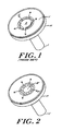
- baffle, screen or similar device at the fluid entrance to the sensor, as shown in FIG. 1 , in order to protect the deflectable member to some extent from fluid-borne contaminants.
- Such devices are disadvantageous, however, because they can become clogged by both solid particulate matter and process vapour residues from the fluids being measured. The clogged screens change the conductance of the fluid and therefore must be regularly removed and cleaned or replaced, necessitating the bypassing and removal of the sensors from the process equipment.
- the baffle shown in FIG. 1 has relatively large openings for the passage of fluid therethrough and thus does not adequately prevent fluid-borne contaminants from reaching the deflectable member within the sensor.
- Example of a prior art pressure sensor/gauge is disclosed in US Patent No. 1,700,449 (Reilly ) which includes a body or disc of porous material to protect the diaphragm from injurious matter.
- some sensors are designed with a relatively large volume for the fluid to be measured, so that solid contaminants in the fluid do not penetrate the sensor sufficiently to reach the deflectable member.
- the use of relatively large fluid volumes in the sensor is disadvantageous because relatively long times are required to evacuate the process lines, thus slowing the fluid measurement process.
- Another object of the present invention is to provide a fluid pressure sensor of the deflectable diaphragm type in which the deflectable diaphragm is not visible or otherwise directly accessible from the exterior of the sensor.
- Yet another object of the invention is to provide a fluid pressure sensor in which solid particulate contaminants of various sizes are trapped and collected remote from the deflectable diaphragm.
- Still another object of the invention is to provide a fluid pressure sensor in which fluid-borne contaminants are excluded from the interior of the sensor without adversely affecting the fluid conductance through the sensor.
- the variable capacitance fluid pressure sensor of the present invention includes a pair of electrically conductive plates, one of which is fixed and other of which is moveable relative to the fixed plate.
- the moveable plate is made of a thin foil or other deflectable member which deflects in response to impingement of fluid against it.
- the deflectable member is connected to a transducer which converts the deflection of the foil to an electrical signal. Deflection of the deflectable member changes the electrical capacitance of the plates and the signals therefrom and is thus a measure of the pressure of the fluid in the sensor.
- the fluid pressure sensor of the present invention includes a contaminant exclusion system which protects the deflectable member inside the sensor from solid contaminants in the fluid being measured. Such contaminants, if in contact with the deflectable member, restrict its movement or otherwise adversely affect its behavior in response to fluid pressure by increasing the weight of the deflectable member or by becoming wedged between the deflectable member and the housing.
- the contaminant exclusion system of the present invention includes various components in the fluid path of the sensor which are designed to collect or trap solid contaminants having a size of approximately 250 micrometers and larger in diameter.
- a system for shielding the deflectable member from contaminants in the fluid comprises a first contaminant collecting element near the fluid inlet to the sensor for collecting relatively large solid contaminants, a second contaminant collecting element between the fluid inlet and the deflectable member for collecting solid contaminants of an intermediate size, and a third contaminant collecting element near the deflectable member for collecting relatively small solid contaminants.
- the first contaminant collecting element comprises an annular channel surrounding, and in fluid communication with, the fluid inlet.
- the maximum dimension, or height, of the entrance to the annular channel from the fluid inlet is small relative to maximum, dimension, or diameter of the entrance to the fluid inlet.
- the second contaminant collecting element comprises a baffle element disposed in the fluid path between the fluid inlet and the deflectable member, and a trap element surrounding, and in fluid communication with, the fluid inlet.
- the baffle element includes a central baffle portion and a peripheral conductance portion, wherein the diameter of the central baffle portion is at least as great as the diameter of the fluid inlet. Fluid impinging on the central baffle portion is thus prevented from impinging directly on the deflectable member.
- the peripheral conductance portion of the baffle element comprises a circumferential region which includes a plurality of radially spaced apertures therein.
- the apertures in the conductance portion of the baffle element permit passage of fluid therethrough and have a radial dimension which is at least as great as the thickness of the central baffle portion.
- the radial dimension of the apertures is not greater than approximately 250 micrometers.
- the trap element is in direct fluid communication with the annular channel, which is in direct fluid communication with the fluid inlet.
- the trap element is adapted for collecting solid contaminants which have a minimum dimension that is greater than the radial dimension of the apertures in the conductance portion of the baffle element.
- the third contaminant collecting element is disposed near the deflectable member and diverts relatively small solid contaminants away from the deflectable member.
- a portion of the housing between the deflectable member and the fluid inlet slopes away from the deflectable member, thus forming an obtuse angle relative to the plane of the deflectable member.
- the angle between the housing and the deflectable member is preferably about 98 degrees.
- FIG. 1 illustrates a portion of a prior art pressure sensor, which comprises a fluid inlet I, a housing H defining an interior ' fluid volume V, and a baffle B disposed between the fluid inlet I and the diaphragm or shaped hud with three radial spokes by which the baffle is mounted to the housing. Fluid passing into the fluid inlet I, although deflected by the baffle B, passes freely through the relatively large openings between the spokes, as indicated by the arrows F. The relatively large size of these openings in the baffle render it a poor shield for the diaphragm, as relatively large fluid-borne contaminants are able to reach, and thus adversely affect the behavior of, the diaphragm.
- FIG. 2 illustrates a portion of a pressure sensor which includes a contaminant exclusion system according to the present invention.
- the baffle B has been replaced with a baffle element B' , described in greater detail below.
- the fluid conductance through this baffle element B' is at all times at least as great as the fluid conductance through the prior art baffle B.
- FIG. 3 illustrates, in simplified cross-section, a variable capacitance fluid pressure sensor 10.
- the sensor 10 includes a housing 12 which defines an interior volume 14 for fluid passage therein and therethrough.
- an electrically conductive deflectable member 16 Disposed within the interior of the housing is an electrically conductive deflectable member 16, such as a diaphragm, which is made of, for example, a thin metal foil.
- a stationary electrically conductive member (not shown) is disposed near the diaphragm.
- the deflectable member 16 is capable of deflecting in response to movement of a fluid against it.
- the two electrically conductive members thus form the moveable and fixed plates of an electrical capacitor.
- the sensor includes a detecting element for detecting the magnitude and direction of deflection of the deflectable member.
- An electrical transducing circuit (not shown) is electrically connected to the plates and detecting element and converts the deflection of the deflectable member 16 into electrical signals representative of the movement of the deflectable member in response to fluid pressure against it, and thus representative of the fluid pressure within the sensor.
- the sensor also includes a fluid inlet 20 which permits passage of fluid from a fluid source (not shown) into the interior volume of the housing.
- the fluid inlet 20 defines a nominal fluid path from the fluid source outside the sensor to the deflectable member 16 within the sensor. Movement of the fluid through the sensor is complex, with variable velocities and pressures ranging from the molecular flow regime to laminar and turbulent flows.
- the contaminant exclusion system of the present invention includes three principal components.
- a first contaminant collecting element 22 is disposed near the fluid inlet 20 and is adapted for collection of relatively large solid contaminants.
- the term "relatively large”, as used herein, refers to solid particles having a size of greater than about 1000 to 2500 micrometers.
- the first contaminant collecting element 22 comprises an annular channel 24 (indicated by dotted lines) surrounding, and in fluid communication with, the fluid inlet 20. Fluid must pass through the annular channel in order to reach the deflectable member 16.
- the maximum dimension, typically the height, of the entrance to the annular channel 24 from the fluid inlet 20 is small relative to the diameter of the fluid inlet.
- the height of the entrance to the annular channel is not greater than, for example, about 2500 micrometers, so that solid contaminants greater than about 2500 micrometers in diameter cannot pass from the fluid inlet 20 into the annular channel 24 and are trapped within the fluid inlet 20.
- This dimension can be selected to exclude contaminants of varying size.
- the diameter of the fluid inlet is approximately 5000 micrometers and the entrance to the annular channel 24 is not smaller than about 1000 micrometers.
- a second contaminant collecting element 26 is disposed between the fluid inlet 22 and the deflectable member 16 and is adapted for collection of intermediate solid contaminants.
- the second contaminant collecting element 26 comprises (a) a baffle element 28 disposed in the fluid path between the fluid inlet and the deflectable member, and (b) a trap element 30 which surrounds and is in fluid communication with the fluid inlet 20 via annular channel 24.
- the baffle element 28 is illustrated in greater detail in FIG. 4 . It is a thin disk-shaped element made of a non-contaminating, corrosion-resistant material, such as stainless steel, inconel or equivalent. As shown in FIG. 3 , the baffle element 28 is disposed in the fluid path in a counterbore 32 in the housing of the sensor.
- the baffle element includes a central baffle portion 34 and a peripheral conductance portion 36, as shown most clearly in FIG. 4 .
- the central baffle portion 34 of the baffle element 28 has a diameter that is not less than, and preferably greater than, the diameter of the fluid inlet 20.
- the baffle element 28 When the baffle element 28 is installed in the sensor, it is interposed between the fluid inlet 20 and the deflectable element 16 so that the deflectable member is entirely blocked by the central baffle portion 34 with respect to the fluid inlet 20.
- This placement of the baffle element 28, and the sizing of the central baffle portion 34 prevent direct contact of the deflectable element 16 by any solid or non-solid fluid-borne particulates or contaminants.
- the deflectable member 16 is located behind, or downstream relative to, the baffle element 28, it is not directly visible or accessible from the exterior of the sensor. Any attempts by operators or other users of the sensor to contact or dislodge the deflectable member via the fluid inlet are prevented.
- the peripheral conductance portion 36 of the baffle element 28 is a circumferential fluid-permeable region surrounding the central baffle portion 34. It includes a plurality of radially spaced apertures 38, the size and spacing of which are preferably optimized to provide a fluid conductance through the baffle element 28 which is at least as great as the fluid conductance through the prior art baffle B shown in the portion of the sensor illustrated in FIG. 1 .
- the radial dimension of the apertures 38 is at least as great as the thickness of the central baffle portion 34, but not greater than about 250 micrometers. Thus, any solid contaminants which are greater than about 250 micrometers in diameter will be prevented from passing through the apertures in the conductance portion of the deflectable member 16 and will be trapped below, or upstream relative to, the baffle element 28.
- the baffle element 28 is preferably made of a corrosion-resistant material, such as stainless steel, inconel or equivalent, which has been photoetched to form the desired number and spacing of radial apertures. Other manufacturing methods for forming the apertures, such as, for example, laser etching, can be used.
- the baffle element 28 is preferably resistance welded in place in a counterbore in the housing in the fluid path between the fluid inlet 20 and the deflectable member 16.
- the trap element 30 is illustrated most clearly in FIG. 3 . It comprises a second annular collecting region which surrounds and is in direct fluid communication with the annular channel 24.
- the peripheral conductance region 36 and the apertures 38 of the baffle element 28 are disposed quite near, and preferably directly downstream of, the trap element 30, as shown in FIG. 3 .
- the radially spaced apertures 38 which are not greater than about 250 micrometers in width, act as a screen between the trap element 30 and the deflectable member 16 and prevent any fluid-borne solid contaminants greater than about 250 micrometers in diameter from contacting the deflectable member.
- a lip 40 on the side of the trap element 30 near the annular channel 24 facilitates collection of these intermediate particulate contaminants in the trap element 30 and also defines the size of the entrance to the annular channel 24, thus defining the particle size of contaminants that are excluded from the annular channel.
- a third contaminant collecting element 42 is disposed near the deflectable member 16 and is illustrated best in FIG 5 .
- the third contaminant collecting element 42 comprises a contour imparted to a portion of the housing 12 at the location at which the deflectable member 16 is joined to the housing, as shown in FIG. 3 and in greater detail in FIG. 5 .
- the contour of the housing at this location diverts relatively small solid contaminants away from the deflectable member.
- a portion of the housing 12 is caused to slope away from the deflectable member 16, such that the angle between the plane of the wall portion of the housing 12 and the plane of the deflectable member 16 at the location of their intersection is greater than 90 degrees.
- the interior of the housing 12 at the location of the deflectable member 16 is contoured by an angle ⁇ so that solid contaminants of less than about 250 micrometers in diameter accumulate away from the deflectable member 16 and not adjacent to it.
- the angle ⁇ of the contour in the wall of the housing is approximately 8 degrees from a nominally perpendicular angle, so that the angle between the plane of the wall portion of the housing and the plane of the deflectable member is approximately 98 degrees, as shown in FIG. 5 .
- the size of the fluid volume between the baffle element 28 and the deflectable element 16 at the location of the contour is greatly exaggerated for clarity in FIGS. 3 and 5 .
Landscapes
- Physics & Mathematics (AREA)
- General Physics & Mathematics (AREA)
- Measuring Fluid Pressure (AREA)
Claims (12)
- Ein Drucksensor (10) für Fluide, mit einem Gehäuse, einem auslenkbaren Bauteil (16) innerhalb des Gehäuses, Fluideinlassmitteln (20), welche ein Fluid in das Gehäuse eintreten lassen und einen Fluidweg zu dem auslenkbaren Bauteil bilden, Mittel zum Erfassen der Auslenkung des auslenkbaren Bauteils in Reaktion auf ein Auftreffen des Fluids auf das auslenkbare Bauteil, und Mittel zum Erzeugen von Signalen, die für den Druck des Fluids auf das auslenkbare Bauteil repräsentativ sind, ein System zum Abschirmen des auslenkbaren Bauteils gegenüber Verunreinigungen in dem Fluid, wobei das System aufweist:A. erste Verunreinigungs-Sammelmittel (22) nahe den Fluideinlassmitteln zum Sammeln von Verunreinigungen mit einer Größe, die größer als eine erste Größe ist, innerhalb des Fluideinlasses, wobei die ersten Verunreinigungs-Sammelmittel einen ringförmigen Kanal (24) aufweisen, der die Fluideinlassmittel (20) umgibt und in Fluidkommunikation mit diesen steht;B. zweite Verunreinigungs-Sammelmittel (26) zwischen den Fluideinlassmitteln und dem auslenkbaren Bauteil zum Sammeln von festen Verunreinigungen die größer als eine zweite Größe und kleiner als die erste Größe sind, wobei die zweiten Verunreinigungs-Sammelmittel aufweisen (i) Ablenkmittel (28) in dem Fluidweg zwischen den Fluideinlassmitteln und dem auslenkbaren Bauteil, und (ii) Fangmittel (30), welche die Fluideinlassmittel umgeben und über einen ringförmigen Kanal (24) in Fluidkommunikation mit diesen stehen, undC. dritte Verunreinigungs-Sammelmittel (42) nahe dem auslenkbaren Bauteil zum Aufsammeln fester Verunreinigungen größer als eine dritte Größe und kleiner als die zweite Größe, wobei die dritten Verunreinigungs-Sammelmittel, Mittel nahe dem auslenkbaren Bauteil zum Abweisen relativ kleiner fester Verunreinigungen weg von dem auslenkbaren Bauteil aufweisen, undD. wobei die maximale Abmessung des Eingans zu dem ringförmigen Kanal (24) von den Fluideinlassmitteln (20) kleiner als der Durchmesser der Fluideinlassmittel ist, und wobei die Fluidleitungsfähigkeit durch den ringförmigen Kanal im wesentlichen gleich der Fluidleitungsfähigkeit der Fluideinlassmittel ist.
- Das System gemäß Anspruch 1, wobei für einen Durchmesser der Fluideinlassmittel (20) von ungefähr 10.000 Mikrometer der Eingang zu dem ringförmigen Kanal (24) von den Fluideinlassmitteln sich ungefähr zwischen 1.000 und 2.500 Mikrometern in einer Richtung längs der longitudinalen Achse der Fluideinlassmittel erstreckt.
- Das System gemäß Anspruch 1, wobei die Ablenkmittel (28) einen zentralen Ablenkabschnitt und einen peripheren Leitungsabschnitt aufweisen, wobei der Durchmesser des zentralen Ablenkabschnitts wenigstens so groß wie der Durchmesser der Fluideinlassmittel (20) ist, wobei das auf dem zentralen Ablenkabschnitt auftreffende Fluid davon abgehalten wird, direkt auf das auslenkbare Bauteil aufzutreffen.
- Das System gemäß Anspruch 3, wobei der periphere Leitungsabschnitt der Ablenkmittel (28) einen umfänglichen Bereich aufweist, der eine Mehrzahl von radial beabstandeten Öffnungen (38) aufweist.
- Das System gemäß Anspruch 4, wobei die Öffnungen in dem Leitungsabschnitt der Ablenkmittel (28) eine Radialabmessung haben, die wenigstens so groß wie die Dicke des zentralen Ablenkabschnitts ist.
- Das System gemäß Anspruch 5, wobei die radiale Abmessung der Öffnungen (38) nicht größer als etwa 250 Mikrometer ist.
- Das System gemäß Anspruch 6, wobei die Abfangmittel (30) zum Sammeln von festen Verunreinigungen mit einer Größe angepasst sind, die größer als die radiale Abmessung der Öffnungen (38) in dem Leitungsabschnitt der Ablenkmittel (28) ist.
- Das System gemäß Anspruch 7, wobei die Verunreinigungen, welche innerhalb der Fangmittel (30) gesammelt werden, eine Größe zwischen 250 und 2.500 Mikrometer aufweisen.
- Das System gemäß Anspruch 1, wobei die Mittel zum Abweisen verhältnismäßig kleiner fester Verunreinigungen weg von dem auslenkbaren Bauteil (16) Mittel aufweisen, zum Ausbilden einer Kontur des Gehäuses nahe dem Ort, an welchem die auslenkbaren Mittel innerhalb des Gehäuses angeordnet sind, wobei das Gehäuse sich in einem Bereich nahe der auslenkbaren Mittel von dem auslenkbaren Bauteil wegneigt.
- Das System gemäß Anspruch 9, wobei das Gehäuse an dem Ort nahe des auslenkbaren Bauteils (16) derart konturiert ist, dass der Winkel zwischen dem Gehäuse und dem auslenkbaren Bauteil größer als 90 Grad ist.
- Das System gemäß Anspruch 10, wobei der Winkel etwa 98 Grad ist.
- Das System gemäß Anspruch 9, wobei die verhältnismäßig kleinen festen Verunreinigungen eine mittlere Größe nicht größer als etwa 250 Mikrometer im Durchmesser aufweisen.
Applications Claiming Priority (3)
| Application Number | Priority Date | Filing Date | Title |
|---|---|---|---|
| US763020 | 1996-12-11 | ||
| US08/763,020 US5811685A (en) | 1996-12-11 | 1996-12-11 | Fluid pressure sensor with contaminant exclusion system |
| PCT/US1997/022291 WO1998026263A1 (en) | 1996-12-11 | 1997-12-05 | Fluid pressure sensor with contaminant exclusion system |
Publications (3)
| Publication Number | Publication Date |
|---|---|
| EP0944818A1 EP0944818A1 (de) | 1999-09-29 |
| EP0944818A4 EP0944818A4 (de) | 2000-06-14 |
| EP0944818B1 true EP0944818B1 (de) | 2011-02-09 |
Family
ID=25066674
Family Applications (1)
| Application Number | Title | Priority Date | Filing Date |
|---|---|---|---|
| EP97951558A Expired - Lifetime EP0944818B1 (de) | 1996-12-11 | 1997-12-05 | Flüssigkeitsdrucksensor mit ein system zum fernhalten von verunreinigungen |
Country Status (8)
| Country | Link |
|---|---|
| US (1) | US5811685A (de) |
| EP (1) | EP0944818B1 (de) |
| JP (1) | JP3280989B2 (de) |
| KR (1) | KR100363947B1 (de) |
| AT (1) | ATE498120T1 (de) |
| DE (1) | DE69740116D1 (de) |
| TW (1) | TW409181B (de) |
| WO (1) | WO1998026263A1 (de) |
Families Citing this family (25)
| Publication number | Priority date | Publication date | Assignee | Title |
|---|---|---|---|---|
| US20040099061A1 (en) | 1997-12-22 | 2004-05-27 | Mks Instruments | Pressure sensor for detecting small pressure differences and low pressures |
| US6443015B1 (en) * | 1999-09-10 | 2002-09-03 | Mks Instruments, Inc. | Baffle for a capacitive pressure sensor |
| US6782754B1 (en) | 2000-07-07 | 2004-08-31 | Rosemount, Inc. | Pressure transmitter for clean environments |
| JP4717237B2 (ja) * | 2001-03-26 | 2011-07-06 | 株式会社鷺宮製作所 | 圧力センサ用ダイヤフラム保護カバーおよび圧力センサ |
| US6901808B1 (en) | 2002-02-12 | 2005-06-07 | Lam Research Corporation | Capacitive manometer having reduced process drift |
| US7252011B2 (en) * | 2002-03-11 | 2007-08-07 | Mks Instruments, Inc. | Surface area deposition trap |
| US6993973B2 (en) | 2003-05-16 | 2006-02-07 | Mks Instruments, Inc. | Contaminant deposition control baffle for a capacitive pressure transducer |
| US7347099B2 (en) * | 2004-07-16 | 2008-03-25 | Rosemount Inc. | Pressure transducer with external heater |
| WO2006039421A1 (en) * | 2004-09-29 | 2006-04-13 | Rosemount Inc. | Pressure transducer with improved process adapter |
| US7201057B2 (en) | 2004-09-30 | 2007-04-10 | Mks Instruments, Inc. | High-temperature reduced size manometer |
| US7141447B2 (en) | 2004-10-07 | 2006-11-28 | Mks Instruments, Inc. | Method of forming a seal between a housing and a diaphragm of a capacitance sensor |
| US7137301B2 (en) | 2004-10-07 | 2006-11-21 | Mks Instruments, Inc. | Method and apparatus for forming a reference pressure within a chamber of a capacitance sensor |
| US7204150B2 (en) | 2005-01-14 | 2007-04-17 | Mks Instruments, Inc. | Turbo sump for use with capacitive pressure sensor |
| US7679033B2 (en) * | 2005-09-29 | 2010-03-16 | Rosemount Inc. | Process field device temperature control |
| JP2007121196A (ja) * | 2005-10-31 | 2007-05-17 | Denso Corp | 圧力センサ |
| US7779698B2 (en) * | 2007-11-08 | 2010-08-24 | Rosemount Inc. | Pressure sensor |
| TWI532982B (zh) | 2011-10-11 | 2016-05-11 | Mks公司 | 壓力感測器 |
| JP5993312B2 (ja) * | 2013-01-16 | 2016-09-14 | 東京エレクトロン株式会社 | 圧力測定器及びその圧力測定器を備える基板処理装置 |
| US9459170B2 (en) * | 2013-09-26 | 2016-10-04 | Rosemount Inc. | Process fluid pressure sensing assembly for pressure transmitters subjected to high working pressure |
| US10352796B2 (en) * | 2014-07-28 | 2019-07-16 | Ford Global Technologies, Llc | Protective cover for pressure sensor nozzle |
| EP3109612A1 (de) * | 2015-06-26 | 2016-12-28 | Nina Wojtas | Mems-abscheidungsfalle für einen unterdruckumformerschutz |
| US9573544B1 (en) * | 2015-08-24 | 2017-02-21 | Ford Global Technologies, Llc | Protective structures for air sensors in a vehicle body structure |
| FI3737926T3 (en) * | 2018-01-09 | 2023-01-13 | Protection device | |
| CN111801561A (zh) * | 2018-03-02 | 2020-10-20 | 格兰富控股联合股份公司 | 压力传感器 |
| CN114264403A (zh) * | 2021-12-03 | 2022-04-01 | 北京晨晶精仪电子有限公司 | 真空规颗粒阻挡结构 |
Citations (2)
| Publication number | Priority date | Publication date | Assignee | Title |
|---|---|---|---|---|
| US4835964A (en) * | 1984-03-31 | 1989-06-06 | Mitsubishi Jidosha Kogyo Kabushiki Kaisha | Diesel particulate oxidizer regeneration system |
| US5315877A (en) * | 1993-02-19 | 1994-05-31 | Kavlico Corporation | Low cost versatile pressure transducer |
Family Cites Families (7)
| Publication number | Priority date | Publication date | Assignee | Title |
|---|---|---|---|---|
| US533136A (en) * | 1895-01-29 | Water-filter | ||
| US1700449A (en) * | 1925-06-05 | 1929-01-29 | Frank C Reilly | Pressure gauge |
| US3231091A (en) * | 1962-10-29 | 1966-01-25 | Pfaudler Permutit Inc | Separator |
| US4177496A (en) * | 1976-03-12 | 1979-12-04 | Kavlico Corporation | Capacitive pressure transducer |
| US4562742A (en) * | 1984-08-07 | 1986-01-07 | Bell Microcomponents, Inc. | Capacitive pressure transducer |
| US4785669A (en) * | 1987-05-18 | 1988-11-22 | Mks Instruments, Inc. | Absolute capacitance manometers |
| US5515711A (en) * | 1995-06-26 | 1996-05-14 | Mks Instruments, Inc. | Pressure measurement and calibration apparatus using gravity-induced diaphragm deflection |
-
1996
- 1996-12-11 US US08/763,020 patent/US5811685A/en not_active Expired - Lifetime
-
1997
- 1997-12-05 KR KR1019997005043A patent/KR100363947B1/ko not_active Expired - Lifetime
- 1997-12-05 DE DE69740116T patent/DE69740116D1/de not_active Expired - Lifetime
- 1997-12-05 WO PCT/US1997/022291 patent/WO1998026263A1/en not_active Ceased
- 1997-12-05 JP JP52682498A patent/JP3280989B2/ja not_active Expired - Lifetime
- 1997-12-05 AT AT97951558T patent/ATE498120T1/de not_active IP Right Cessation
- 1997-12-05 EP EP97951558A patent/EP0944818B1/de not_active Expired - Lifetime
- 1997-12-09 TW TW086118486A patent/TW409181B/zh active
Patent Citations (2)
| Publication number | Priority date | Publication date | Assignee | Title |
|---|---|---|---|---|
| US4835964A (en) * | 1984-03-31 | 1989-06-06 | Mitsubishi Jidosha Kogyo Kabushiki Kaisha | Diesel particulate oxidizer regeneration system |
| US5315877A (en) * | 1993-02-19 | 1994-05-31 | Kavlico Corporation | Low cost versatile pressure transducer |
Also Published As
| Publication number | Publication date |
|---|---|
| WO1998026263A1 (en) | 1998-06-18 |
| US5811685A (en) | 1998-09-22 |
| KR100363947B1 (ko) | 2002-12-11 |
| JP2000512388A (ja) | 2000-09-19 |
| EP0944818A4 (de) | 2000-06-14 |
| KR20000057436A (ko) | 2000-09-15 |
| TW409181B (en) | 2000-10-21 |
| JP3280989B2 (ja) | 2002-05-13 |
| EP0944818A1 (de) | 1999-09-29 |
| ATE498120T1 (de) | 2011-02-15 |
| DE69740116D1 (de) | 2011-03-24 |
Similar Documents
| Publication | Publication Date | Title |
|---|---|---|
| EP0944818B1 (de) | Flüssigkeitsdrucksensor mit ein system zum fernhalten von verunreinigungen | |
| EP1483558B1 (de) | Fangvorrichtung mit oberfläche für ablagerungen | |
| KR101061408B1 (ko) | 용량차 압력 트랜스듀서를 갖는 오염 물질 피착 제어 배플 | |
| EP1340971A2 (de) | Stauscheibe für einen kapazitiven Drucksensor | |
| EP2527022B1 (de) | Teilchendetektor | |
| US4176545A (en) | Electronic engine wear detector | |
| US20100283450A1 (en) | Particle detection | |
| CN116986550B (zh) | 气流传感器及气流传感器封装结构 | |
| US4035788A (en) | Incipient fire detector | |
| US5705930A (en) | Gas path electrostatic sensor | |
| KR102252221B1 (ko) | 축전 용량식 진공게이지 | |
| US7318338B2 (en) | Measuring device for measuring aerosol | |
| EP0221770B1 (de) | Ionisationsdetektionskammer |
Legal Events
| Date | Code | Title | Description |
|---|---|---|---|
| PUAI | Public reference made under article 153(3) epc to a published international application that has entered the european phase |
Free format text: ORIGINAL CODE: 0009012 |
|
| 17P | Request for examination filed |
Effective date: 19990701 |
|
| AK | Designated contracting states |
Kind code of ref document: A1 Designated state(s): AT BE CH DE DK ES FI FR GB GR IE IT LI LU MC NL PT SE |
|
| A4 | Supplementary search report drawn up and despatched |
Effective date: 20000428 |
|
| AK | Designated contracting states |
Kind code of ref document: A4 Designated state(s): AT BE CH DE DK ES FI FR GB GR IE IT LI LU MC NL PT SE |
|
| RIC1 | Information provided on ipc code assigned before grant |
Free format text: 7G 01L 9/12 A, 7G 01L 19/06 B |
|
| 17Q | First examination report despatched |
Effective date: 20080520 |
|
| RAP1 | Party data changed (applicant data changed or rights of an application transferred) |
Owner name: MKS INSTRUMENTS, INC. |
|
| GRAP | Despatch of communication of intention to grant a patent |
Free format text: ORIGINAL CODE: EPIDOSNIGR1 |
|
| GRAS | Grant fee paid |
Free format text: ORIGINAL CODE: EPIDOSNIGR3 |
|
| GRAA | (expected) grant |
Free format text: ORIGINAL CODE: 0009210 |
|
| AK | Designated contracting states |
Kind code of ref document: B1 Designated state(s): AT BE CH DE DK ES FI FR GB GR IE IT LI LU MC NL PT SE |
|
| REG | Reference to a national code |
Ref country code: GB Ref legal event code: FG4D |
|
| REG | Reference to a national code |
Ref country code: CH Ref legal event code: EP |
|
| REG | Reference to a national code |
Ref country code: IE Ref legal event code: FG4D |
|
| REF | Corresponds to: |
Ref document number: 69740116 Country of ref document: DE Date of ref document: 20110324 Kind code of ref document: P |
|
| REG | Reference to a national code |
Ref country code: DE Ref legal event code: R096 Ref document number: 69740116 Country of ref document: DE Effective date: 20110324 |
|
| REG | Reference to a national code |
Ref country code: NL Ref legal event code: VDEP Effective date: 20110209 |
|
| PG25 | Lapsed in a contracting state [announced via postgrant information from national office to epo] |
Ref country code: PT Free format text: LAPSE BECAUSE OF FAILURE TO SUBMIT A TRANSLATION OF THE DESCRIPTION OR TO PAY THE FEE WITHIN THE PRESCRIBED TIME-LIMIT Effective date: 20110609 Ref country code: SE Free format text: LAPSE BECAUSE OF FAILURE TO SUBMIT A TRANSLATION OF THE DESCRIPTION OR TO PAY THE FEE WITHIN THE PRESCRIBED TIME-LIMIT Effective date: 20110209 Ref country code: ES Free format text: LAPSE BECAUSE OF FAILURE TO SUBMIT A TRANSLATION OF THE DESCRIPTION OR TO PAY THE FEE WITHIN THE PRESCRIBED TIME-LIMIT Effective date: 20110520 Ref country code: GR Free format text: LAPSE BECAUSE OF FAILURE TO SUBMIT A TRANSLATION OF THE DESCRIPTION OR TO PAY THE FEE WITHIN THE PRESCRIBED TIME-LIMIT Effective date: 20110510 |
|
| PG25 | Lapsed in a contracting state [announced via postgrant information from national office to epo] |
Ref country code: NL Free format text: LAPSE BECAUSE OF FAILURE TO SUBMIT A TRANSLATION OF THE DESCRIPTION OR TO PAY THE FEE WITHIN THE PRESCRIBED TIME-LIMIT Effective date: 20110209 Ref country code: BE Free format text: LAPSE BECAUSE OF FAILURE TO SUBMIT A TRANSLATION OF THE DESCRIPTION OR TO PAY THE FEE WITHIN THE PRESCRIBED TIME-LIMIT Effective date: 20110209 Ref country code: FI Free format text: LAPSE BECAUSE OF FAILURE TO SUBMIT A TRANSLATION OF THE DESCRIPTION OR TO PAY THE FEE WITHIN THE PRESCRIBED TIME-LIMIT Effective date: 20110209 Ref country code: AT Free format text: LAPSE BECAUSE OF FAILURE TO SUBMIT A TRANSLATION OF THE DESCRIPTION OR TO PAY THE FEE WITHIN THE PRESCRIBED TIME-LIMIT Effective date: 20110209 |
|
| PG25 | Lapsed in a contracting state [announced via postgrant information from national office to epo] |
Ref country code: DK Free format text: LAPSE BECAUSE OF FAILURE TO SUBMIT A TRANSLATION OF THE DESCRIPTION OR TO PAY THE FEE WITHIN THE PRESCRIBED TIME-LIMIT Effective date: 20110209 |
|
| PLBE | No opposition filed within time limit |
Free format text: ORIGINAL CODE: 0009261 |
|
| STAA | Information on the status of an ep patent application or granted ep patent |
Free format text: STATUS: NO OPPOSITION FILED WITHIN TIME LIMIT |
|
| 26N | No opposition filed |
Effective date: 20111110 |
|
| REG | Reference to a national code |
Ref country code: DE Ref legal event code: R097 Ref document number: 69740116 Country of ref document: DE Effective date: 20111110 |
|
| PG25 | Lapsed in a contracting state [announced via postgrant information from national office to epo] |
Ref country code: IT Free format text: LAPSE BECAUSE OF FAILURE TO SUBMIT A TRANSLATION OF THE DESCRIPTION OR TO PAY THE FEE WITHIN THE PRESCRIBED TIME-LIMIT Effective date: 20110209 |
|
| PG25 | Lapsed in a contracting state [announced via postgrant information from national office to epo] |
Ref country code: MC Free format text: LAPSE BECAUSE OF NON-PAYMENT OF DUE FEES Effective date: 20111231 |
|
| REG | Reference to a national code |
Ref country code: CH Ref legal event code: PL |
|
| REG | Reference to a national code |
Ref country code: FR Ref legal event code: ST Effective date: 20120831 |
|
| REG | Reference to a national code |
Ref country code: IE Ref legal event code: MM4A |
|
| PG25 | Lapsed in a contracting state [announced via postgrant information from national office to epo] |
Ref country code: IE Free format text: LAPSE BECAUSE OF NON-PAYMENT OF DUE FEES Effective date: 20111205 Ref country code: CH Free format text: LAPSE BECAUSE OF NON-PAYMENT OF DUE FEES Effective date: 20111231 Ref country code: LI Free format text: LAPSE BECAUSE OF NON-PAYMENT OF DUE FEES Effective date: 20111231 |
|
| PG25 | Lapsed in a contracting state [announced via postgrant information from national office to epo] |
Ref country code: FR Free format text: LAPSE BECAUSE OF NON-PAYMENT OF DUE FEES Effective date: 20120102 |
|
| PG25 | Lapsed in a contracting state [announced via postgrant information from national office to epo] |
Ref country code: LU Free format text: LAPSE BECAUSE OF NON-PAYMENT OF DUE FEES Effective date: 20111205 |
|
| PGFP | Annual fee paid to national office [announced via postgrant information from national office to epo] |
Ref country code: GB Payment date: 20161228 Year of fee payment: 20 |
|
| PGFP | Annual fee paid to national office [announced via postgrant information from national office to epo] |
Ref country code: DE Payment date: 20161229 Year of fee payment: 20 |
|
| REG | Reference to a national code |
Ref country code: DE Ref legal event code: R071 Ref document number: 69740116 Country of ref document: DE |
|
| REG | Reference to a national code |
Ref country code: GB Ref legal event code: PE20 Expiry date: 20171204 |
|
| PG25 | Lapsed in a contracting state [announced via postgrant information from national office to epo] |
Ref country code: GB Free format text: LAPSE BECAUSE OF EXPIRATION OF PROTECTION Effective date: 20171204 |