EP0944536B1 - Bandumreifung - Google Patents
Bandumreifung Download PDFInfo
- Publication number
- EP0944536B1 EP0944536B1 EP97946229A EP97946229A EP0944536B1 EP 0944536 B1 EP0944536 B1 EP 0944536B1 EP 97946229 A EP97946229 A EP 97946229A EP 97946229 A EP97946229 A EP 97946229A EP 0944536 B1 EP0944536 B1 EP 0944536B1
- Authority
- EP
- European Patent Office
- Prior art keywords
- strap
- screw
- binding
- web
- flange
- Prior art date
- Legal status (The legal status is an assumption and is not a legal conclusion. Google has not performed a legal analysis and makes no representation as to the accuracy of the status listed.)
- Expired - Lifetime
Links
- 101000845183 Homo sapiens Tetratricopeptide repeat protein 5 Proteins 0.000 title claims abstract description 55
- 102100031280 Tetratricopeptide repeat protein 5 Human genes 0.000 title claims abstract description 55
- 230000000717 retained effect Effects 0.000 claims abstract 2
- 230000007704 transition Effects 0.000 claims description 2
- 238000000034 method Methods 0.000 description 4
- 239000002184 metal Substances 0.000 description 3
- 238000003892 spreading Methods 0.000 description 3
- 230000000284 resting effect Effects 0.000 description 2
- 238000005266 casting Methods 0.000 description 1
- 238000005242 forging Methods 0.000 description 1
- 238000004080 punching Methods 0.000 description 1
Images
Classifications
-
- F—MECHANICAL ENGINEERING; LIGHTING; HEATING; WEAPONS; BLASTING
- F16—ENGINEERING ELEMENTS AND UNITS; GENERAL MEASURES FOR PRODUCING AND MAINTAINING EFFECTIVE FUNCTIONING OF MACHINES OR INSTALLATIONS; THERMAL INSULATION IN GENERAL
- F16L—PIPES; JOINTS OR FITTINGS FOR PIPES; SUPPORTS FOR PIPES, CABLES OR PROTECTIVE TUBING; MEANS FOR THERMAL INSULATION IN GENERAL
- F16L3/00—Supports for pipes, cables or protective tubing, e.g. hangers, holders, clamps, cleats, clips, brackets
- F16L3/08—Supports for pipes, cables or protective tubing, e.g. hangers, holders, clamps, cleats, clips, brackets substantially surrounding the pipe, cable or protective tubing
- F16L3/12—Supports for pipes, cables or protective tubing, e.g. hangers, holders, clamps, cleats, clips, brackets substantially surrounding the pipe, cable or protective tubing comprising a member substantially surrounding the pipe, cable or protective tubing
- F16L3/1211—Supports for pipes, cables or protective tubing, e.g. hangers, holders, clamps, cleats, clips, brackets substantially surrounding the pipe, cable or protective tubing comprising a member substantially surrounding the pipe, cable or protective tubing with a substantially radial tightening or securing member
-
- B—PERFORMING OPERATIONS; TRANSPORTING
- B65—CONVEYING; PACKING; STORING; HANDLING THIN OR FILAMENTARY MATERIAL
- B65D—CONTAINERS FOR STORAGE OR TRANSPORT OF ARTICLES OR MATERIALS, e.g. BAGS, BARRELS, BOTTLES, BOXES, CANS, CARTONS, CRATES, DRUMS, JARS, TANKS, HOPPERS, FORWARDING CONTAINERS; ACCESSORIES, CLOSURES, OR FITTINGS THEREFOR; PACKAGING ELEMENTS; PACKAGES
- B65D63/00—Flexible elongated elements, e.g. straps, for bundling or supporting articles
- B65D63/02—Metallic straps, tapes, or bands; Joints between ends thereof
- B65D63/06—Joints produced by application of separate securing members, e.g. by deformation thereof
- B65D63/08—Joints using buckles, wedges, or like locking members attached to the ends of the elements
Definitions
- the invention relates to a strap binding according to the precharacterizing part of claim 1.
- the above-mentioned strap binding is known from DE 1 649 451 U.
- Said strap binding comprises a stirrup bent in the form of the letter U, both ends of flanges of the said stirrup resting on the object to be strapped. Due to the action of the said binding strap when it is tightened up, the said stirrup is pressed against the surface of the object to be strapped.
- this known solution has a relatively important drawback, namely the flanges are not mutually connected, which results in the said flanges being spread apart and the connection being cut. Also a relatively great danger exists that the flanges with their sharp end surfaces might penetrate into the object to be strapped and thus damage the surface thereof.
- the aim of the invention is to create a strap binding which would allow a quick and easy tying and binding of objects of larger diameters, that are basically unknown in advance, without any need to have recourse to a special tool or more persons or specially adapted binding straps.
- the strap binding according to the invention comprises a stirrup which is formed as an elongated channel shaped in a cross-section substantially as a letter U and comprises a web and flanges standing approximately perpendicularly thereto which at each free end comprise cuffs arranged approximately perpendicularly thereto.
- the web is preferably formed centrically to its longitudinal and transversal axes, with a nut rim arranged perpendicularly thereto into which a holding, or better, a tightening screw is screwed.
- the latter comprises a suitably shaped screw-end at its first end and a suitably shaped holding portion subjected to the application purpose at its opposite end.
- Said nut rim can alternatively be shaped as a nut welded onto the web.
- An eye bolt, a lifting eye bolt, an eyelet bolt or similar can be used as the holding or tightening screw.
- the screw-end of said screw can have a form of a chamfered end, a truncated cone point or similar.
- each flange of the stirrup is formed with a preferably rectangular cutout extending from the web towards the cuff up to approximately half the length of each flange.
- the binding strap is led through the cutouts intended to strap or tie an object or a bundle of objects.
- each flange into the cuff and preferably centrically to the web and coaxially with the holding or tightening screw, a rectangular cutout is formed the ends of which are folded inwards along the cuffs.
- the holding strap prevents the flanges from spreading when the binding strap is stretched.
- each cuff In its lower rim area and axially to the screw below said cutout, each cuff is formed with a step extending from the edge of the cuff towards said cutout.
- each flange is formed with at least two through-holes extending perpendicularly thereto, which are preferably arranged symmetrically to the longitudinal axis of the screw and are intended for screws for fixing another beam or auxiliary means.
- each cuff can be formed with a pair of rectangular cutouts being distant from the center-line of the screw and intended to receive auxiliary fixing or binding straps.
- the strap binding according to the invention can be made of a metal sheet according to the process of cold forming, or cast, whereby in the latter case it comprises a web arranged between the flanges and integral therewith, which prevents the flanges from spreading.
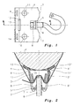
- a stirrup 1 of the strap binding according to the invention is formed as an elongated channel shaped in a cross-section (Fig. 2) essentially as a letter U and comprises a web 2 and flanges 3, 3' standing approximately perpendicularly thereto and having at each free end cuffs 4, 4' arranged approximately perpendicularly thereto.
- the latter are intended to lie against an object or a bundle of objects P that is/are to be tied or tightened with a strap binding according to the invention, e.g. onto a concrete post of an electric conduit with a diameter that changes in length.
- the web 2 is preferably formed centrically to its longitudinal and transversal axes with a nut rim 5 arranged perpendicularly thereto into which either a holding or a tightening screw 6 is screwed.
- the rim 5 is formed either by a process of deep drawing and additional cut-in of an internal thread or is just an ordinary nut welded to the web 2, for instance.
- the screw 6 comprises a suitably shaped screw-end which can have a form of a chamfered end or a truncated cone point, at its opposite end there is a suitably shaped holding portion that is subjected to the application purpose.
- the screw 6 can be an eye bolt, a lifting eye bolt, an eyelet bolt or similar.
- the web 2 On the side averted from an object P the web 2 further comprises multiple bulges 7 arranged symmetrically to their longitudinal and transversal axes intended to support an auxiliary element resting against the web 2 on said side.
- each flange 3, 3' is formed with a preferably rectangular cutout 8, 8' through which a primary binding strap 9 is led.
- Each cutout 8, 8' extends from the web 2 towards the cuff 4, 4' up to approximately half the length of each flange.
- Each flange 3, 3' is further formed with at least two through-holes 10, 11 extending perpendicularly thereto which are preferably arranged symmetrically to the longitudinal axis of the screw 6.
- the through-holes 10, 11 are intended for screws for fixing another beam or auxiliary means.
- each flange 3, 3' into the cuff 4, 4' and preferably centrically to the web 2 and coaxially with the screw 6 preferably a rectangular cutout 12, 12' is formed.
- Each cuff 4, 4' is formed in its rim area and axially with the screw 6 below the cutout 12, 12' with a step 13, 13' extending from the edge of the cuff 4, 4' towards the cutout 12, 12'.
- Each cuff 4, 4' is further formed with a pair of rectangular cutouts 14, 14' being distant from the center-line of the screw 6 and intended to receive secondary, i.e. auxiliary, fixing or binding straps, respectively.
- the stirrup 1 is made of a metal sheet by means of the process of cold forming and punching. It can alternatively be made by means of casting or forging process and subsequent finishing of respective cutouts and holes. If the stirrup 1 is made of a metal sheet or forged, a holding strap 15 is led through the cutouts 12, 12' which is folded under the cuff 4, 4' at each end. The strap 15 prevents the flanges 3, 3' from spreading when an object or a bundle of objects P is tied or tightened with a strap binding according to the invention. If the stirrup 1 is cast, then also a respective web known per se and not shown is cast which connects both flanges 3, 3' thus making the strap 15 superfluous.
- the strap binding according to the invention is fixed to an object P as follows (see Fig. 2).
- a strap 15 is led through the cutouts 12, 12', the ends of which are folded inwards along the cuffs 4, 4'.
- the screw 6 is screwed into the nut rim 5 to such depth that only a small portion of it projects out of the rim.
- the binding strap 9 is led, the first end of which is folded through the cutout 12' (Fig. 2), e.g., inside the stirrup 1.
- the opposite, free end of the strap 9 is now led around the object P and pushed again through the cutouts 8, 8', this time from the opposite side.
- the free end of the strap 9 is kept tight either by hand or a suitable tool while the screw 6 is screwed until it rests with its screw-end against the superposed layers of the strap 9.
- the strap 9, in the area of acting of the screw-end of the screw 6, moves towards the object P thus being more and more tightened.
- the screw-end 6, according to the principle of deep drawing essentially penetrates into the superposed layers of the strap 9 thus creating a tensionally and form-locking connection which offers good holding of the strap 9.
Landscapes
- Engineering & Computer Science (AREA)
- General Engineering & Computer Science (AREA)
- Mechanical Engineering (AREA)
- Package Frames And Binding Bands (AREA)
- Clamps And Clips (AREA)
- Microwave Tubes (AREA)
- Finger-Pressure Massage (AREA)
Claims (8)
- Bandumreifung zum Festmachen von Objekten (P) durch mechanische Spannung, beispielsweise von Stäben, Stangen und ähnlichem, wobei die Bandumreifung einen starren Bügel (1) aufweist, der als ein verlängerter Kanal mit einem im wesentlichen wie der Buchstabe U gestalteten Querschnitt ausgebildet ist, und einen Steg (2) und Flansche (3, 3'), die ungefähr senkrecht dazu stehen, und ein sich dadurch erstreckendes Umreifungsband (9) aufweist, wobei das Umreifungsband (9) durch die Ausschnitte (8, 8') hindurch um das festzumachende Objekt (P) herumgeführt ist, wobei das Umreifungsband (9) mittels einer Befestigungsschraube (6) durch mechanische Spannung und durch Formschluss davon abgehalten wird, herauszufallen, dadurch gekennzeichnet, dassdie Flansche (3, 3') an jedem freien Ende Manschetten (4, 4') aufweisen, die in einem Winkel zu dem Objekt (P) angeordnet sind, wobei der Steg (2) mit einem Muttern-Rand (5) versehen ist, vorzugsweise mittig der Längs- und Quer-Achse des Stegs, so dass jeder Flansch (3, 3') im Bereich des Muttern-Rands (5) mit einem Ausschnitt (8, 8') versehen ist, vorzugsweise rechtwinklig, der sich von dem Steg (2) in Richtung zu der Manschette (4, 4') bis ungefähr zur halben Länge jedes Flansches hin erstreckt; dass im Übergangsbereich jedes Flansches (3, 3') in die Manschette (4, 4') ein Ausschnitt (12, 12') vorzugsweise rechtwinklig ausgebildet ist, vorzugsweise in einer mittigen Achse der Flansche (3, 3'); und dass jede Manschette (4, 4') in ihrem unteren Randbereich und in einer mittigen Achse des Flansches (3, 3') unter dem Abschnitt (12, 12') mit einer Abstufung (13, 13') versehen ist, die sich vom Rand der Manschette (4, 4') in Richtung zu dem Ausschnitt (12, 12') erstreckt,die Halte- oder Festmach-Schraube (6) in den Muttern-Rand (5) hineingeschraubt wird und an ihrem ersten Ende ein zweckmäßig gestaltetes Schraubenende und an ihrem entgegengesetzten Ende einen Halteabschnitt aufweist, der zweckmäßig und entsprechend dessen Anwendung gestaltet ist, undein Halteband (15) durch die Ausschnitte (12, 12') hindurchgeführt ist, dessen Enden nach innen hin entlang der Manschetten (4, 4') eingeklappt sind.
- Bandumreifung nach Anspruch 1, dadurch gekennzeichnet, dass jeder Flansch (3, 3') mit mindestens zwei Durchgangslöchern (10, 11) versehen ist, die sich senkrecht dazu erstrecken, die vorzugsweise symmetrisch zur Längsachse der Schraube (6) angeordnet sind und für Schrauben zum Befestigen eines anderen Trägers oder von Hilfsmitteln bestimmt sind.
- Bandumreifung nach Anspruch 1 oder 2, dadurch gekennzeichnet, dass eine über das Schraubenende der Schraube (6) auf das Band (9) ausgeübte Kraft bewirkt, dass gemäß dem Prinzip des Tiefziehens das Schraubenende im wesentlichen in die vorgelagerten Schichten des Bandes (9) eindringt, so durch mechanische Spannung und Formschluss eine Verbindung erzeugt und ein gutes Halten des Bandes sicherstellt.
- Bandumreifung nach einem der vorangehenden Ansprüche, dadurch gekennzeichnet, dass jede Manschette (4, 4') mit einem Paar rechtwinkliger Ausschnitte (14, 14') versehen ist, die von der Mittellinie der Schraube (6) entfernt sind und dafür vorgesehen sind, sekundäre, das heißt behelfsmäßige Befestigungs- bzw. Umreifungsbänder aufzunehmen.
- Bandumreifung nach einem der vorangehenden Ansprüche, dadurch gekennzeichnet, dass ein Steg zwischen den Flanschen (3, 3') angeordnet ist, wobei der Steg einstückig mit den Flanschen ausgebildet ist.
- Bandumreifung nach einem der vorangehenden Ansprüche, dadurch gekennzeichnet, dass der Muttern-Rand (5) als eine an den Steg (2) angeschweißte Mutter ausgebildet ist.
- Bandumreifung nach einem der vorangehenden Ansprüche, dadurch gekennzeichnet, dass die Schraube (6) eine Ösenschraube, eine Heißöse, ein ösenförmiger Bolzen oder ähnliches ist.
- Bandumreifung nach einem der vorangehenden Ansprüche, dadurch gekennzeichnet, dass das Schraubenende der Schraube (6) die Gestalt eines abgerundeten Endes, der Spitze eines Kegelstumpfes oder ähnlichem hat.
Applications Claiming Priority (3)
| Application Number | Priority Date | Filing Date | Title |
|---|---|---|---|
| SI9600365 | 1996-12-12 | ||
| SI9600365A SI9600365B (sl) | 1996-12-12 | 1996-12-12 | Tracna vez |
| PCT/SI1997/000034 WO1998025837A1 (en) | 1996-12-12 | 1997-12-05 | Strap binding |
Publications (2)
| Publication Number | Publication Date |
|---|---|
| EP0944536A1 EP0944536A1 (de) | 1999-09-29 |
| EP0944536B1 true EP0944536B1 (de) | 2001-03-07 |
Family
ID=20431971
Family Applications (1)
| Application Number | Title | Priority Date | Filing Date |
|---|---|---|---|
| EP97946229A Expired - Lifetime EP0944536B1 (de) | 1996-12-12 | 1997-12-05 | Bandumreifung |
Country Status (5)
| Country | Link |
|---|---|
| EP (1) | EP0944536B1 (de) |
| AT (1) | ATE199528T1 (de) |
| DE (1) | DE69704214T2 (de) |
| SI (1) | SI9600365B (de) |
| WO (1) | WO1998025837A1 (de) |
Family Cites Families (2)
| Publication number | Priority date | Publication date | Assignee | Title |
|---|---|---|---|---|
| GB817045A (en) * | 1957-06-04 | 1959-07-22 | Lanz Ag Hermann | Improvements relating to fixing bridles and tightening devices thereof |
| DE1649451U (de) * | 1952-10-14 | 1953-01-15 | Karst Fa Robert | Stahlbandschelle. |
-
1996
- 1996-12-12 SI SI9600365A patent/SI9600365B/sl active Search and Examination
-
1997
- 1997-12-05 DE DE69704214T patent/DE69704214T2/de not_active Expired - Lifetime
- 1997-12-05 AT AT97946229T patent/ATE199528T1/de active
- 1997-12-05 EP EP97946229A patent/EP0944536B1/de not_active Expired - Lifetime
- 1997-12-05 WO PCT/SI1997/000034 patent/WO1998025837A1/en not_active Ceased
Also Published As
| Publication number | Publication date |
|---|---|
| SI9600365B (sl) | 2006-02-28 |
| EP0944536A1 (de) | 1999-09-29 |
| ATE199528T1 (de) | 2001-03-15 |
| WO1998025837A1 (en) | 1998-06-18 |
| SI9600365A (sl) | 1998-06-30 |
| DE69704214D1 (de) | 2001-04-12 |
| DE69704214T2 (de) | 2001-10-04 |
Similar Documents
| Publication | Publication Date | Title |
|---|---|---|
| US4073317A (en) | Adjustable clamping device | |
| US4756130A (en) | Apparatus for reinforcing utility poles and the like | |
| US5163643A (en) | Span clamp assembly | |
| US4662035A (en) | Wire clamp | |
| GB2389386A (en) | Fall protection system and apparatus | |
| US6783104B1 (en) | Deformable clamp employed to stiffen hanger rod | |
| US4111579A (en) | Scaffolding | |
| EP0044044B1 (de) | Vorrichtung für Gerüste | |
| JPH09210141A (ja) | ワイヤロープ係止具 | |
| US4223497A (en) | Coupling assembly | |
| US3903574A (en) | Cable clamp | |
| US6068318A (en) | Clamp for conveyor belts | |
| JPS609285Y2 (ja) | Pc鋼材の中間定着具 | |
| EP0944536A1 (de) | Bandumreifung | |
| NZ205187A (en) | Cable clamp with side aperture and wedge lock | |
| EP0554972A1 (de) | Kupplungsanordnung für Bewehrungsstäbe | |
| US3330516A (en) | Cable clamp | |
| GB2240804A (en) | Scaffolding coupler | |
| US2613964A (en) | Clamp | |
| WO1994007070A1 (en) | Apparatus for mounting load supporting equipment on a fixed support | |
| JP3013240U (ja) | ジョイント金具 | |
| JPS5936725Y2 (ja) | 棒状体の結合具 | |
| CA1162034A (en) | Bundle clamp | |
| US5579560A (en) | Cable clamp | |
| GB2240359A (en) | Clamp |
Legal Events
| Date | Code | Title | Description |
|---|---|---|---|
| PUAI | Public reference made under article 153(3) epc to a published international application that has entered the european phase |
Free format text: ORIGINAL CODE: 0009012 |
|
| 17P | Request for examination filed |
Effective date: 19990709 |
|
| AK | Designated contracting states |
Kind code of ref document: A1 Designated state(s): AT DE ES FI FR GB IT SE |
|
| 17Q | First examination report despatched |
Effective date: 19991004 |
|
| GRAG | Despatch of communication of intention to grant |
Free format text: ORIGINAL CODE: EPIDOS AGRA |
|
| GRAG | Despatch of communication of intention to grant |
Free format text: ORIGINAL CODE: EPIDOS AGRA |
|
| GRAH | Despatch of communication of intention to grant a patent |
Free format text: ORIGINAL CODE: EPIDOS IGRA |
|
| GRAH | Despatch of communication of intention to grant a patent |
Free format text: ORIGINAL CODE: EPIDOS IGRA |
|
| GRAA | (expected) grant |
Free format text: ORIGINAL CODE: 0009210 |
|
| AK | Designated contracting states |
Kind code of ref document: B1 Designated state(s): AT DE ES FI FR GB IT SE |
|
| PG25 | Lapsed in a contracting state [announced via postgrant information from national office to epo] |
Ref country code: FR Free format text: LAPSE BECAUSE OF FAILURE TO SUBMIT A TRANSLATION OF THE DESCRIPTION OR TO PAY THE FEE WITHIN THE PRESCRIBED TIME-LIMIT Effective date: 20010307 Ref country code: FI Free format text: LAPSE BECAUSE OF FAILURE TO SUBMIT A TRANSLATION OF THE DESCRIPTION OR TO PAY THE FEE WITHIN THE PRESCRIBED TIME-LIMIT Effective date: 20010307 Ref country code: ES Free format text: THE PATENT HAS BEEN ANNULLED BY A DECISION OF A NATIONAL AUTHORITY Effective date: 20010307 |
|
| REF | Corresponds to: |
Ref document number: 199528 Country of ref document: AT Date of ref document: 20010315 Kind code of ref document: T |
|
| REF | Corresponds to: |
Ref document number: 69704214 Country of ref document: DE Date of ref document: 20010412 |
|
| ITF | It: translation for a ep patent filed | ||
| PG25 | Lapsed in a contracting state [announced via postgrant information from national office to epo] |
Ref country code: SE Free format text: LAPSE BECAUSE OF FAILURE TO SUBMIT A TRANSLATION OF THE DESCRIPTION OR TO PAY THE FEE WITHIN THE PRESCRIBED TIME-LIMIT Effective date: 20010607 |
|
| EN | Fr: translation not filed | ||
| REG | Reference to a national code |
Ref country code: GB Ref legal event code: IF02 |
|
| PLBE | No opposition filed within time limit |
Free format text: ORIGINAL CODE: 0009261 |
|
| STAA | Information on the status of an ep patent application or granted ep patent |
Free format text: STATUS: NO OPPOSITION FILED WITHIN TIME LIMIT |
|
| 26N | No opposition filed | ||
| PGFP | Annual fee paid to national office [announced via postgrant information from national office to epo] |
Ref country code: GB Payment date: 20121227 Year of fee payment: 16 |
|
| PGFP | Annual fee paid to national office [announced via postgrant information from national office to epo] |
Ref country code: AT Payment date: 20121221 Year of fee payment: 16 |
|
| PGFP | Annual fee paid to national office [announced via postgrant information from national office to epo] |
Ref country code: DE Payment date: 20130220 Year of fee payment: 16 |
|
| REG | Reference to a national code |
Ref country code: DE Ref legal event code: R119 Ref document number: 69704214 Country of ref document: DE |
|
| REG | Reference to a national code |
Ref country code: AT Ref legal event code: MM01 Ref document number: 199528 Country of ref document: AT Kind code of ref document: T Effective date: 20131205 |
|
| GBPC | Gb: european patent ceased through non-payment of renewal fee |
Effective date: 20131205 |
|
| REG | Reference to a national code |
Ref country code: DE Ref legal event code: R119 Ref document number: 69704214 Country of ref document: DE Effective date: 20140701 |
|
| PG25 | Lapsed in a contracting state [announced via postgrant information from national office to epo] |
Ref country code: DE Free format text: LAPSE BECAUSE OF NON-PAYMENT OF DUE FEES Effective date: 20140701 |
|
| PG25 | Lapsed in a contracting state [announced via postgrant information from national office to epo] |
Ref country code: AT Free format text: LAPSE BECAUSE OF NON-PAYMENT OF DUE FEES Effective date: 20131205 Ref country code: GB Free format text: LAPSE BECAUSE OF NON-PAYMENT OF DUE FEES Effective date: 20131205 |
|
| PGFP | Annual fee paid to national office [announced via postgrant information from national office to epo] |
Ref country code: IT Payment date: 20141223 Year of fee payment: 18 |
|
| PG25 | Lapsed in a contracting state [announced via postgrant information from national office to epo] |
Ref country code: IT Free format text: LAPSE BECAUSE OF NON-PAYMENT OF DUE FEES Effective date: 20151205 |