EP0944533B1 - Aligned web in a container - Google Patents
Aligned web in a container Download PDFInfo
- Publication number
- EP0944533B1 EP0944533B1 EP97913000A EP97913000A EP0944533B1 EP 0944533 B1 EP0944533 B1 EP 0944533B1 EP 97913000 A EP97913000 A EP 97913000A EP 97913000 A EP97913000 A EP 97913000A EP 0944533 B1 EP0944533 B1 EP 0944533B1
- Authority
- EP
- European Patent Office
- Prior art keywords
- web
- tubular chamber
- thickness
- elongated tubular
- area
- Prior art date
- Legal status (The legal status is an assumption and is not a legal conclusion. Google has not performed a legal analysis and makes no representation as to the accuracy of the status listed.)
- Expired - Lifetime
Links
- 238000005192 partition Methods 0.000 claims description 19
- 238000000034 method Methods 0.000 claims description 12
- 230000003247 decreasing effect Effects 0.000 claims description 5
- 230000009977 dual effect Effects 0.000 abstract description 15
- 230000003313 weakening effect Effects 0.000 abstract description 6
- 239000000463 material Substances 0.000 abstract description 4
- 230000004048 modification Effects 0.000 abstract 1
- 238000012986 modification Methods 0.000 abstract 1
- 239000004033 plastic Substances 0.000 description 6
- 229920003023 plastic Polymers 0.000 description 6
- -1 polyethylene Polymers 0.000 description 5
- 239000004698 Polyethylene Substances 0.000 description 2
- 238000004519 manufacturing process Methods 0.000 description 2
- 229920000573 polyethylene Polymers 0.000 description 2
- VEXZGXHMUGYJMC-UHFFFAOYSA-M Chloride anion Chemical compound [Cl-] VEXZGXHMUGYJMC-UHFFFAOYSA-M 0.000 description 1
- 239000004743 Polypropylene Substances 0.000 description 1
- 239000000853 adhesive Substances 0.000 description 1
- 230000001070 adhesive effect Effects 0.000 description 1
- DQXBYHZEEUGOBF-UHFFFAOYSA-N but-3-enoic acid;ethene Chemical compound C=C.OC(=O)CC=C DQXBYHZEEUGOBF-UHFFFAOYSA-N 0.000 description 1
- 238000010276 construction Methods 0.000 description 1
- 229920001577 copolymer Polymers 0.000 description 1
- 239000005038 ethylene vinyl acetate Substances 0.000 description 1
- 239000004715 ethylene vinyl alcohol Substances 0.000 description 1
- 238000010438 heat treatment Methods 0.000 description 1
- RZXDTJIXPSCHCI-UHFFFAOYSA-N hexa-1,5-diene-2,5-diol Chemical compound OC(=C)CCC(O)=C RZXDTJIXPSCHCI-UHFFFAOYSA-N 0.000 description 1
- 229920001200 poly(ethylene-vinyl acetate) Polymers 0.000 description 1
- 239000005020 polyethylene terephthalate Substances 0.000 description 1
- 229920000139 polyethylene terephthalate Polymers 0.000 description 1
- 229920001155 polypropylene Polymers 0.000 description 1
- 229920000915 polyvinyl chloride Polymers 0.000 description 1
- 239000004800 polyvinyl chloride Substances 0.000 description 1
- 239000000126 substance Substances 0.000 description 1
- 229920001169 thermoplastic Polymers 0.000 description 1
- 239000004416 thermosoftening plastic Substances 0.000 description 1
Images

Classifications
-
- B—PERFORMING OPERATIONS; TRANSPORTING
- B65—CONVEYING; PACKING; STORING; HANDLING THIN OR FILAMENTARY MATERIAL
- B65D—CONTAINERS FOR STORAGE OR TRANSPORT OF ARTICLES OR MATERIALS, e.g. BAGS, BARRELS, BOTTLES, BOXES, CANS, CARTONS, CRATES, DRUMS, JARS, TANKS, HOPPERS, FORWARDING CONTAINERS; ACCESSORIES, CLOSURES, OR FITTINGS THEREFOR; PACKAGING ELEMENTS; PACKAGES
- B65D35/00—Pliable tubular containers adapted to be permanently or temporarily deformed to expel contents, e.g. collapsible tubes for toothpaste or other plastic or semi-liquid material; Holders therefor
- B65D35/22—Pliable tubular containers adapted to be permanently or temporarily deformed to expel contents, e.g. collapsible tubes for toothpaste or other plastic or semi-liquid material; Holders therefor with two or more compartments
-
- Y—GENERAL TAGGING OF NEW TECHNOLOGICAL DEVELOPMENTS; GENERAL TAGGING OF CROSS-SECTIONAL TECHNOLOGIES SPANNING OVER SEVERAL SECTIONS OF THE IPC; TECHNICAL SUBJECTS COVERED BY FORMER USPC CROSS-REFERENCE ART COLLECTIONS [XRACs] AND DIGESTS
- Y10—TECHNICAL SUBJECTS COVERED BY FORMER USPC
- Y10S—TECHNICAL SUBJECTS COVERED BY FORMER USPC CROSS-REFERENCE ART COLLECTIONS [XRACs] AND DIGESTS
- Y10S493/00—Manufacturing container or tube from paper; or other manufacturing from a sheet or web
- Y10S493/916—Pliable container
- Y10S493/917—Envelope
- Y10S493/92—Envelope having plural compartments
Definitions
- This invention relates to a tubular chamber according to the preamble of claims 10 and 14 with an aligned web which divides the tubular chamber into a plurality of subsidiary chambers. This invention further relates to a method of aligning a web within a tubular chamber according to the preamble of claim 1. Additionally, this invention relates to a tubular container comprised of a tubular chamber with an aligned web.
- Dual chamber tubular containers have been available for use for several decades. These are tubes that are generally circular or elliptical in shape and which have a web that divides the tubular container into two or more separate chambers. Usually these tubular containers are crimp sealed on the lower end in the same manner as conventional single chamber tubular containers and have one or more dispensing shoulders and nozzles attached to an upper end. The chamber forming web and the sidewalls are attached to this dispensing shoulder so that the chambers are separate from the crimp seal through the dispensing opening of the tubular container.
- the chamber forming web will have a width greater than the major cross-sectional axis of the tubular container. For a circular tubular container this would be a width greater than the diameter of the tubular container.
- One reason for this need is that it is desired in many uses to crimp seal the tubular container with the web disposed linearly in the crimp seal. In this way this will be a three layer seal. If the web is not so disposed in the crimp seal then the web overlaps in areas with an uneven three to five layer crimp seal. Usually, this will result in a weak crimp seal. When disposed in the crimp seal, the web will have to be about one half the circumference of the tubular container when the tubular container is of a round shape.
- the present invention is directed to techniques for keeping the web positioned in a more diametric manner across the tubular container. The web is kept away from the container sidewalls.
- U.S Patent 1,894,115 discloses a dual chamber tube where the dividing web can be of a length greater than the diameter of the tube.
- the web as shown is not sufficiently wide to be within the crimp seal. To be within the crimp seal, the web would have to have a width of at least one half the circumference of the tube for a tube with a circular cross-section.
- U.S. Patent 3,506,157 discloses a tube with two or three chambers.
- Patent 3,788,520 discloses a tube according to the preamble of claims 10 and 14 and a method according to the preamble of claim 1 with a web that has a corrugated-like fold.
- U.S. Patent 5,244,120 discloses a dual chamber tube where the dividing web has a width greater than the diameter of the tube. However, this is not a sufficient length to be disposed in the crimp seal of the tubular container. These webs are not one half the circumference of the containers, in relation to the diameter d of the tube, the web should be 1/2 ( ⁇ d). A web that has a length of at least 1/2 ⁇ d will have a sufficient width for dual tube construction.
- Patent 5,628,429 published on 13.05.1997 and corresponding to WO-A-97/18999 published on 29.05.1997 with a filing date of 30.10.1996 and a priority date of 22.11.1995 discloses a partition insert in a tube container where this partition insert is not attached to the sidewall, but only in a contacting relationship. Also, the partition insert is relatively thick.
- the web dividing wall or walls will in most instances, have a width dimension greater than or equal to the cross-sectional dimension of the tubular container.
- this will be a width dimension greater than the diameter of the tubular container.
- the width of the web will be at least about one half the circumference of the tube. In mathematical terms this would be 1/2 ⁇ (d) where d is the diameter of the tube or about 1.57 (d). That is, the web should have a width of about one half again the diameter of the tubular container.
- a thin, flexible web having a width of 1.57 (d) or greater presents problems in a dual chamber tubular container. The web has a tendency to fall into contact with the inner surface of the sidewall.
- This problem Qf keeping a thin, flexible web aligned across the tubular container is solved by providing one or more longitudinal modified areas such as thinned or weakened areas to cause the thin, flexible web to have at least one fold point, the thickness of the thin, flexible web being about .015mm to about 0.2mm.
- Such a fold point can be at the center of the web or within about 80% of the of the distance of the center point of the web to the edge of the web at the sidewall. When there is such a fold point, the web material will gather more transversely across the tubular container rather than along the inner surface of a sidewall of the tubular container.
- At least one or more thinned or weakened modified areas can be an area of decreased thickness, or can be recess in the film that acts as a hinge or can be a treatment which makes the area more flexible.
- This area of decreased thickness can be from about a groove recess to about 50%, and preferably to about 25% of the width of the web. When a recess it will be about 0.1mm to about 2mm in width.
- the thinned or weakened modified areas can be created by running the web film through pinch rolls or other shaped rolls which splay the plastic to produce a thinned region. This can be from about 5% to about 50% of the thickness of the web. A wider thinned or weakened region will allow for a decreased thinning or weakening while a recess will need a greater thinning or weakening but at a more concentrated location.
- the thinned or weakened modified areas can also be created by heating, irradiation or a chemical treatment of the plastic surface to decrease the thickness or to otherwise affect the web material to selectively make it more flexible.
- This creating a thinned area solves the problem of disposing the web across the tubular chamber and out of contact with the sidewalls of the tubular container. There is created a fold point so that the web is disposed more diametrically across the tubular chamber.
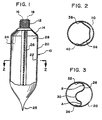
- Figure 1 is an elevational, sectional view of the present dual chamber tubular container with a web having a thinned area.
- Figure 2 is a cross-sectional view of the web of the tubular container with no thinned area.
- Figure 3 is a cross-sectional view of the web of the tubular container with a thinned area.
- Figure 4 is a cross-sectional view of a common position of a web having a constant thickness.
- Figure 5 is a cross-sectional view of the position of a web that has a centrally located recess thinned area.
- Figure 6 is a cross-sectional view of a web with one wide thinned area.
- Figure 7 is a cross-sectional view of a web with two thinned areas.
- FIG. 1 there is shown a dual chamber tube 10 having a shoulder 14 and a dispensing end 12.
- the dispensing end carries apertures 16 and 18 for the dispensing of products from chambers 24 and 28 respectively.
- Web 26 separates the tubular container 10 into the two chambers formed by the web and sidewall 20.
- a crimp 25 seals the bottom of the tubular container.
- the web 26 is disposed in the crimp 25. This will keep the web disposed across the tubular container.
- Figure 3 is a cross-sectional view of the tubular container of Figure 1.
- Web 26 is attached to sidewall 20 at 32 and 34.
- the web has a thinned area at 30.
- This thinned area is essentially at a mid-point of the web. This is one preferred position. However, it is very effective if the modified thinned area is within about the central 80% of the lateral dimension of the web. That is, the thinned area is about ten percent of the distance from each of the sidewalls. This is shown as being between points of A and B in Figure 2.
- Figure 2 is a cross-sectional view of the web of the tubular container with no thinned area for the dispensing of products from chambers 24 and 28 respectively.
- Web 36 separates the tubular container 10 into the two chambers formed by the web 26 and sidewall 20.
- a crimp 25 seals the bottom of the tubular container.
- the web 26 is disposed in the crimp 25.
- the web is attached to the sidewall at 38 and 40. The web in this embodiment adjusts to a point adjacent to sidewall 20.
- Figure 4 is an elevational view of a web that has a recess 42 in one side. This is shown more clearly in Figure 5.
- This area 42 is a narrow thinned area with this area 42 acting as a hinge around which the web 40 can bend. There can be more than one recess 42.
- Figure 6 is a cross-sectional view of a web 44 where there is a thinned area 46 between points A and B. Points A and B are about one quarter of the distance in from the ends of the web 44. This thinned area is in contrast to the recess shown in Figure 5.
- Figure 7 shows two thinned areas 52 and 54 in web 50.
- the weakening or thinning can be accomplished mechanically, thermally or chemically. It is preferred to accomplish the thinning or weakening mechanically.
- a pinch roll, or some other shaped roll is passed in contact with the film at a pressure of about 1 kg/cm 2 to about 6 kg/cm 2 . This force splays the plastic and produces a weakened area.
- This step can be a part of making the film where the weakened areas are formed just prior to the film being placed onto rolls.
- the film also can be mechanically modified just prior to the film being used. In this embodiment as the film is being unwound, one or more longitudinal weakened or thinned areas are produced. Thermally, heat can be provided to thin an area by flowing some of the plastic to another area. Chemically, some of the film surface can be leached away.
- This invention is directed to the use of thin walled webs.
- These are thin flexible webs having a thickness of about .015mm to 0.2mm, and preferably from about .025mm to .015mm.
- the thinned area can be one or more recesses or thinned areas. This thinned area can be located at the center point of the web to any point to about 10% of the distance from the sidewall.
- the web will be attached to the sidewalls by heat bonding, although adhesives would be used.
- the web material can be of essentially any plastic, with thermoplastics being preferred. These preferred plastics include polyethylene, polypropylene, copolymers of polyethylene and of polypropylene, ethylene vinyl alcohol, ethylene vinyl acetate, polyethylene terephthalate, polyvinyl chloride and polyvinylidine chloride.
Landscapes
- Engineering & Computer Science (AREA)
- Mechanical Engineering (AREA)
- Tubes (AREA)
- Bag Frames (AREA)
- Details Of Rigid Or Semi-Rigid Containers (AREA)
- Containers And Plastic Fillers For Packaging (AREA)
- Auxiliary Devices For And Details Of Packaging Control (AREA)
- Packages (AREA)
- Cartons (AREA)
Abstract
Description
Claims (18)
- A method of aligning a web (26) in an elongated tubular chamber (10) comprisingcharacterized in that said partition web (26) has a thickness of about 0.015 mm to about 0.2 mm and an area (30) of modified thickness is placed longitudinally along said partition web.providing a sidewall web (20) and a partition web (26), said partition web having a width greater than the cross-sectional diameter of the tubular chamber;overlaying at least a part of said sidewall web (20) with said partition web (26) and attaching the edges (32, 34) of said partition web to said sidewall web; andoverlaying the longitudinal edges of said sidewall web (20) and attaching said longitudinal edges to form said elongated tubular chamber (10);
- A method as in claim 1 wherein said partition web (26) has a width of at least about one-half the circumference the elongated tubular chamber.
- A method as in claim 1 wherein there are at least two longitudinal areas (52, 54) of modified thickness along said partition web (50).
- A method as in claim 1 wherein said at least one area (30) of modified thickness is located at about a midpoint of said partition web (26).
- A method as in claim 4 wherein said at least one area (30) of modified thickness is located from said midpoint of said partition web (26) to a point about 10% of the distance to a sidewall of said tubular chamber.
- A method as in claim 1 wherein said at least one area (30) of modified thickness is an area of decreased thickness.
- A method as in claim 1 wherein said sidewall (20) as a thickness of about 0.25mm to about 2mm.
- A method as in claim 7 wherein a dispensing shoulder (14) is attached to one end of said partition web (26) and said sidewall web (20) of said elongated tubular chamber, said dispensing shoulder (14) and said elongated tubular chamber (10) forming two continuous separate chambers (24, 28).
- A method of aligning a web (26) as in claim 8 wherein an other end of said elongated tubular chamber is sealed, the partition web being disposed in the seal (25).
- An elongated tubular chamber (10) with an aligned partition web (26) comprising an elongated tubular chamber having an inner surface and open at each end, a partition web (26) having two longitudinal edges (32, 34) within said elongated tubular chamber, each of said longitudinal edges attached to the inner surface of said elongated tubular chamber, characterized in that said web (26) has a thickness of about 0.015 mm to about 0.2 mm and at least one longitudinally extending area (30) of modified thickness.
- An elongated tubular chamber (10) as in claim 10 wherein said at least one longitudinally extending area (30) of modified thickness is at about a center point of said web.
- An elongated tubular chamber (10) as in claim 10 wherein said at least one longitudinally extending area (30) of modified thickness is located from said midpoint to spaced about 10% of the distance to the inner surface of said elongated tubular chamber.
- An elongated tubular chamber (10) as in claim 10 wherein a sidewall web (20) has a thickness of about 0.25 mm to about 2 mm.
- A tubular container comprising an elongated tubular chamber (10) closed at one end and having a dispensing opening (12) at another end, said elongated tubular chamber having an inner surface and a partition web (26) having two longitudinal edges (32, 34) within said elongated tubular chamber, each of said longitudinal edges attached to the inner surface of said elongated tubular chamber, characterised in that said web (26) has a thickness of about 0.015 mm to about 0.2 mm and at least one longitudinally extending area (30) of modified thickness.
- A tubular container as in claim 14 wherein said at least one longitudinally extending area (30) of modified thickness is from about the center point of said web to about 10 percent of the distance to the inner surface of said elongated tubular chamber.
- A tubular container as in claim 14 wherein said area (30) of modified thickness is an area of decreased thickness.
- A tubular container as in claim 14 wherein there are up to three areas of modified thickness.
- A tubular container as in claim 14 wherein a sidewall web (20) for forming said tubular chamber (10) has a thickness of about 0.25 mm to about 2 mm.
Applications Claiming Priority (3)
| Application Number | Priority Date | Filing Date | Title |
|---|---|---|---|
| US740970 | 1985-06-04 | ||
| US08/740,970 US5782384A (en) | 1996-11-05 | 1996-11-05 | Aligned web in a container |
| PCT/US1997/019785 WO1998019929A1 (en) | 1996-11-05 | 1997-10-30 | Aligned web in a container |
Publications (2)
| Publication Number | Publication Date |
|---|---|
| EP0944533A1 EP0944533A1 (en) | 1999-09-29 |
| EP0944533B1 true EP0944533B1 (en) | 2001-05-30 |
Family
ID=24978814
Family Applications (1)
| Application Number | Title | Priority Date | Filing Date |
|---|---|---|---|
| EP97913000A Expired - Lifetime EP0944533B1 (en) | 1996-11-05 | 1997-10-30 | Aligned web in a container |
Country Status (8)
| Country | Link |
|---|---|
| US (1) | US5782384A (en) |
| EP (1) | EP0944533B1 (en) |
| AT (1) | ATE201646T1 (en) |
| AU (1) | AU736860B2 (en) |
| BR (1) | BR9712740A (en) |
| CA (1) | CA2269503A1 (en) |
| DE (1) | DE69705062D1 (en) |
| WO (1) | WO1998019929A1 (en) |
Cited By (1)
| Publication number | Priority date | Publication date | Assignee | Title |
|---|---|---|---|---|
| CN102730288A (en) * | 2012-06-05 | 2012-10-17 | 夏旻 | Easily-folded toothpaste tube |
Families Citing this family (14)
| Publication number | Priority date | Publication date | Assignee | Title |
|---|---|---|---|---|
| DE19522169C2 (en) * | 1995-06-19 | 1997-05-28 | Automation Industrielle Sa | Process for producing a multi-layer tubular body with at least one partition for a tube |
| DE19712736C1 (en) * | 1997-03-26 | 1998-11-12 | Maegerle Karl Lizenz | Process for manufacturing a multi-chamber packaging tube |
| EP1051328B1 (en) * | 1997-12-05 | 2003-03-26 | Norden Pac Development Ab | Method and device for end closure of packaging tubes |
| DE19808649A1 (en) * | 1998-02-28 | 1999-09-02 | Iwk Verpackungstechnik Gmbh | Method for filling a two-chamber tube and device for carrying it out |
| CH693027A5 (en) * | 1998-05-07 | 2003-01-31 | Maegerle Karl Lizenz | A process for preparing a multi-chamber packaging tube. |
| DE19900670C2 (en) * | 1999-01-11 | 2002-11-28 | Automation Industrielle Sa | Process for the continuous production of tube tubes |
| US6901935B2 (en) * | 2002-11-19 | 2005-06-07 | Kiss Products, Inc. | Device for removing artificial fingernails and fingernail polish |
| US6669390B1 (en) | 2002-11-22 | 2003-12-30 | John J. Porter | Breath freshener with mouthwash atomizer |
| DE10360627B4 (en) * | 2003-12-19 | 2006-02-23 | Heraeus Kulzer Gmbh | Multi-component cartridge and its application |
| USD575160S1 (en) | 2007-08-22 | 2008-08-19 | Idispense, Llc | Container |
| USD617197S1 (en) | 2009-03-25 | 2010-06-08 | Idispense, Llc | Container |
| CN102470210B (en) * | 2009-07-14 | 2014-02-12 | 赛诺菲-安万特德国有限公司 | Medicament container |
| KR101088471B1 (en) * | 2010-04-26 | 2011-11-30 | 박은정 | Double tube container and its manufacturing method |
| US11002039B2 (en) | 2012-04-20 | 2021-05-11 | Triteq Lock And Security, L.L.C. | Electronic controlled handles |
Family Cites Families (74)
| Publication number | Priority date | Publication date | Assignee | Title |
|---|---|---|---|---|
| US1363064A (en) * | 1919-08-13 | 1920-12-21 | Stegath Frederick Hartman | Duplex tube |
| US1676734A (en) * | 1922-12-16 | 1928-07-10 | Gilmont Products Corp | Apparatus and method for filling collapsible tubes |
| US1828865A (en) * | 1923-02-20 | 1931-10-27 | Gilmont Products Corp | Apparatus for filling multicompartment containers |
| US1894115A (en) * | 1931-04-11 | 1933-01-10 | Michael F Murphy | Plural chambered collapsible tube |
| US2103817A (en) * | 1935-03-04 | 1937-12-28 | Gerh Arehns Mek Verkst Ab | Apparatus for filling containers |
| US2107987A (en) * | 1935-12-09 | 1938-02-08 | Gerh Arehns Mek Verkst Ab | Apparatus for delivering portions of relatively mobile material |
| US2517027A (en) * | 1945-09-19 | 1950-08-01 | Rado Leopold | Collapsible tubelike container for pastes |
| US2661871A (en) * | 1950-04-17 | 1953-12-08 | Alfred G Huenergardt | Multiple liquid dispensing container |
| US2959327A (en) * | 1957-04-19 | 1960-11-08 | Lever Brothers Ltd | Striping dispenser |
| US2939610A (en) * | 1957-10-03 | 1960-06-07 | Johnson & Johnson | Dispensing device |
| US2944705A (en) * | 1958-04-10 | 1960-07-12 | Regent Plastics Inc | Dispenser for paste material |
| DK93503C (en) * | 1961-04-27 | 1962-05-21 | Leo Pharm Prod Ltd | Double tube consisting of a tube body and a tube sleeve fitting around the tube body. |
| US3105615A (en) * | 1961-07-10 | 1963-10-01 | Koga Motoyuki | Lid means including a mixing chamber for a container with plural spaced outlets |
| US3182728A (en) * | 1962-04-25 | 1965-05-11 | Charles L Zabriskie | Container for mixing two fire extinguishing fluids during discharge |
| US3197071A (en) * | 1962-12-03 | 1965-07-27 | Colgate Palmolive Co | Multiple compartment dispenser |
| US3227319A (en) * | 1964-02-21 | 1966-01-04 | Rosier Jean-Jacques | Flexible tube |
| US3365111A (en) * | 1966-03-21 | 1968-01-23 | Int Paper Co | Laminated container |
| US3380632A (en) * | 1966-06-15 | 1968-04-30 | Henry A. Wilson | Collapsible container |
| US3506157A (en) * | 1968-12-11 | 1970-04-14 | Joseph Dukess | Pronged closure device for multiple compartment squeeze tube |
| US3788520A (en) * | 1971-07-21 | 1974-01-29 | J Dukess | Multiple compartment tube with resilient divider |
| IT974494B (en) * | 1972-12-06 | 1974-06-20 | Colgate Palmolive Co | APPARATUS AND PROCEDURE FOR FILLING CONTAINERS WITH DETACHABLE WALLS WITH A PLURALITY OF FLUENT MATERIALS, FOR EXAMPLE TOOTHPASTES |
| US3948704A (en) * | 1973-11-13 | 1976-04-06 | The Procter & Gamble Company | Method of and apparatus for making longitudinally partitioned tubular bodies and container assemblies |
| US3980222A (en) * | 1973-11-13 | 1976-09-14 | The Procter & Gamble Company | Longitudinally partitioned tubular body |
| US4099651A (en) * | 1975-05-22 | 1978-07-11 | Von Winckelmann Emil H | Closure assembly for collapsible tube dispensers, and the like |
| US4014463A (en) * | 1975-11-28 | 1977-03-29 | Kenics Corporation | Plural component dispenser |
| US4046288A (en) * | 1976-02-06 | 1977-09-06 | Carl Bergman | Plural chamber dispenser |
| US4040420A (en) * | 1976-04-22 | 1977-08-09 | General Dynamics | Packaging and dispensing kit |
| US4089437A (en) * | 1976-06-18 | 1978-05-16 | The Procter & Gamble Company | Collapsible co-dispensing tubular container |
| US4211341A (en) * | 1976-08-16 | 1980-07-08 | Colgate-Palmolive Company | Dispensing container of stabilized extrudable dentifrice containing normally chemically reactive components |
| US4148417A (en) * | 1976-11-29 | 1979-04-10 | Simmons Michael J | Fluid dispenser |
| US4260077A (en) * | 1979-10-04 | 1981-04-07 | Aelco Corporation | Dual separable dispenser |
| USD277072S (en) | 1981-08-11 | 1985-01-08 | Joachim Czech | Dispenser for flowable products |
| US4487757A (en) * | 1981-12-28 | 1984-12-11 | Colgate-Palmolive Company | Dispensing container of toothpaste which effervesces during toothbrushing |
| US4687663B1 (en) * | 1983-03-01 | 1997-10-07 | Chesebrough Ponds Usa Co | Dental preparation article and method for storage and delivery thereof |
| US4528180A (en) * | 1983-03-01 | 1985-07-09 | Schaeffer Hans A | Dental preparation, article and method for storage and delivery thereof |
| GB2142611A (en) * | 1983-06-28 | 1985-01-23 | Unilever Plc | Method and apparatus for filling a toothpaste tube |
| DE3420324A1 (en) * | 1984-05-30 | 1985-12-05 | Lechler Chemie Gmbh, 7000 Stuttgart | Dispensing device for a plurality of flowable material components |
| US4742940A (en) * | 1985-02-25 | 1988-05-10 | Package Research | Dispenser for flowable materials |
| USD306554S (en) | 1986-08-18 | 1990-03-13 | The English Glass Company Limited | Dispenser |
| FR2603558B1 (en) * | 1986-09-04 | 1988-11-18 | Oreal | DISPENSING HEAD OF A PASTY PRODUCT RESULTING FROM THE MIXTURE OF TWO SEPARATELY STORED COMPONENTS AND PACKAGING ASSEMBLY WITH SUCH A DISPENSING HEAD |
| GB8623643D0 (en) * | 1986-10-02 | 1986-11-05 | Unilever Plc | Oral products |
| SE458677B (en) * | 1986-10-06 | 1989-04-24 | Norden Packaging Mach | DEVELOPING MACHINE DEVICE |
| US4747517A (en) * | 1987-03-23 | 1988-05-31 | Minnesota Mining And Manufacturing Company | Dispenser for metering proportionate increments of polymerizable materials |
| USD307113S (en) | 1987-05-07 | 1990-04-10 | Sterling Drug Inc. | Bottle |
| DE3873628D1 (en) * | 1987-06-10 | 1992-09-17 | Wilhelm A Keller | DOUBLE DISCHARGE CARTRIDGE FOR TWO-COMPONENT DIMENSIONS. |
| USD311861S (en) | 1987-08-05 | 1990-11-06 | Reckitt & Colman | Combined applicator bottle and closure therefor |
| FR2627463B1 (en) * | 1988-02-23 | 1990-06-15 | Simon Patrick | DEFORMABLE TUBULAR CONTAINER AND ITS ONE PIECE MANUFACTURING METHOD |
| JP3023124B2 (en) * | 1988-11-16 | 2000-03-21 | フィットブレッド アンド カンパニー ピーエルシー. | Plastic blow-molded bottle and method for producing plastic bottle. |
| USD315496S (en) | 1988-12-06 | 1991-03-19 | Chesebrough-Pond's Inc. | Dispensing container |
| JP2836746B2 (en) * | 1989-01-31 | 1998-12-14 | ポーラ化成工業株式会社 | Filling nozzle |
| US5145668A (en) * | 1989-03-13 | 1992-09-08 | American Dental Association Health Foundation | Fluoride containing mouth rinses, dentifrices, and gels |
| US5020694A (en) * | 1989-03-16 | 1991-06-04 | Chesebrough-Pond's, Inc. | Multi-cavity dispensing container |
| US4964539A (en) * | 1989-04-06 | 1990-10-23 | Seaquist Closures | Multiple chamber dispensing container and closure system |
| US4974756A (en) * | 1989-07-14 | 1990-12-04 | Minnesota Mining And Manufacturing Company | Double barrel dispensing container and cap therefor |
| US5078963A (en) * | 1990-02-14 | 1992-01-07 | Mallen Ted A | Method of preventing fires in engine and exhaust systems using high nickel mallen alloy |
| FR2673948B1 (en) * | 1991-03-13 | 1995-03-10 | Dow Corning Sa | EXPANDABLE SILICONE COMPOSITIONS USEFUL IN THE PRODUCTION OF MEDICAL DRESSINGS. |
| US5137178A (en) * | 1991-04-17 | 1992-08-11 | Elizabeth Arden Company. Division Of Conopco, Inc. | Dual tube dispenser |
| DE4120644C1 (en) * | 1991-06-22 | 1993-03-25 | Raimund Andris Gmbh & Co Kg, 7730 Villingen-Schwenningen, De | |
| US5269441A (en) * | 1992-01-31 | 1993-12-14 | Cp Packaging, Inc., Sub. Of Wheaton Industries | Dual chamber medicament dispenser having a pleated common wall |
| US5244120A (en) * | 1992-08-19 | 1993-09-14 | Cp Packaging, Inc. | Dual chamber medicament dispenser |
| WO1993008117A1 (en) * | 1991-10-24 | 1993-04-29 | Cp Packaging, Inc. | Container closure assemblies |
| US5209376A (en) * | 1992-03-13 | 1993-05-11 | The Procter & Gamble Company | Co-dispensing pump for fluent materials |
| US5289949A (en) * | 1992-06-22 | 1994-03-01 | Chesebrough-Pond's Usa Co., Division Of Conopco, Inc. | Multi-cavity dispensing refill cartridge |
| US5332124A (en) * | 1993-05-17 | 1994-07-26 | Chesebrough-Pond's, Usa Co., A Division Of Conopco, Inc. | Multi-cavity dispensing refill cartridge |
| ES2105621T3 (en) * | 1992-12-22 | 1997-10-16 | Unilever Nv | RECHARGEABLE DISTRIBUTION WITH MULTIPLE CAVITIES AND REFILL CARTRIDGE FOR THE SAME. |
| US5335827A (en) * | 1992-12-22 | 1994-08-09 | Chesebrough-Pond's Usa Co., A Division Of Conopco, Inc. | Multi-cavity dispensing refill cartridge |
| USD356026S (en) | 1993-07-01 | 1995-03-07 | Chesebrough-Pond's Usa Co., Division Of Conopco, Inc. | Dual-compartment dispenser |
| US5318203A (en) * | 1993-07-01 | 1994-06-07 | Chesebrough-Pond's Usa Co., Division Of Conopco, Inc. | Dual chamber dispenser |
| US5476647A (en) * | 1993-09-13 | 1995-12-19 | American Dental Association Health Foundation | Complex calcium and fluoride containing mouth rinses, dentifrices, and chewable tablets |
| DE4335970A1 (en) * | 1993-10-21 | 1995-04-27 | Hilti Ag | Foil bag pack with foil bag and bottom part |
| ES2126733T3 (en) * | 1994-07-18 | 1999-04-01 | Wilhelm A Keller | CARTRIDGE WITH PERMUTABLE CONTENT PACKAGE. |
| DE19522169C2 (en) * | 1995-06-19 | 1997-05-28 | Automation Industrielle Sa | Process for producing a multi-layer tubular body with at least one partition for a tube |
| DE29515380U1 (en) * | 1995-09-26 | 1995-11-23 | Josef Wischerath Gmbh & Co. Kg, 50259 Pulheim | Device for dispensing a viscous medium |
| US5628429A (en) * | 1995-11-22 | 1997-05-13 | Enamelon, Inc. | Plural chambered squeezable dispensing tube |
-
1996
- 1996-11-05 US US08/740,970 patent/US5782384A/en not_active Expired - Lifetime
-
1997
- 1997-10-30 DE DE69705062T patent/DE69705062D1/en not_active Expired - Lifetime
- 1997-10-30 BR BR9712740-0A patent/BR9712740A/en not_active IP Right Cessation
- 1997-10-30 AU AU50057/97A patent/AU736860B2/en not_active Ceased
- 1997-10-30 EP EP97913000A patent/EP0944533B1/en not_active Expired - Lifetime
- 1997-10-30 WO PCT/US1997/019785 patent/WO1998019929A1/en not_active Ceased
- 1997-10-30 CA CA002269503A patent/CA2269503A1/en not_active Abandoned
- 1997-10-30 AT AT97913000T patent/ATE201646T1/en not_active IP Right Cessation
Cited By (1)
| Publication number | Priority date | Publication date | Assignee | Title |
|---|---|---|---|---|
| CN102730288A (en) * | 2012-06-05 | 2012-10-17 | 夏旻 | Easily-folded toothpaste tube |
Also Published As
| Publication number | Publication date |
|---|---|
| CA2269503A1 (en) | 1998-05-14 |
| ATE201646T1 (en) | 2001-06-15 |
| DE69705062D1 (en) | 2001-07-05 |
| AU736860B2 (en) | 2001-08-02 |
| EP0944533A1 (en) | 1999-09-29 |
| AU5005797A (en) | 1998-05-29 |
| BR9712740A (en) | 1999-10-19 |
| US5782384A (en) | 1998-07-21 |
| WO1998019929A1 (en) | 1998-05-14 |
Similar Documents
| Publication | Publication Date | Title |
|---|---|---|
| EP0944533B1 (en) | Aligned web in a container | |
| US4930905A (en) | Thermoplastic bag with integral draw strip and method of manufacture | |
| AU724943B2 (en) | An improved fastener assembly, fastener tape material, bag utilizing fastener tape material, and method of manufacture thereof | |
| US6063223A (en) | Dual chamber flexible tube dispensing package and method of making | |
| US6106153A (en) | Tape-sealed bag and method for producing the same | |
| US4076121A (en) | Reinforced thin wall plastic bag, and method and apparatus to make material for such bags | |
| EP1182144B1 (en) | Fitment for spouted pouch | |
| EP1816083B1 (en) | Method for manufacturing a pouch | |
| US4998563A (en) | Plastic pipe | |
| US8070016B2 (en) | Pouch for refill of contents | |
| EP0809933A2 (en) | Drip irrigation hose | |
| JPH04215957A (en) | Flexible bag | |
| US20020015541A1 (en) | Sealed enclosure, method for the manufacture thereof, and method of packaging a beverage in said enclosure | |
| US4593408A (en) | Easy open/reclose device for flexible packages | |
| US4368765A (en) | Flexible bag with recessed scrapless hanger | |
| EP2065313A2 (en) | Spouted pouch | |
| AU2017286562B2 (en) | Easy peel pouch | |
| JPS6215412B2 (en) | ||
| US4844327A (en) | Pack for fluid media | |
| EP1412255B1 (en) | Flattening and gusseting device, method and bag | |
| US3734388A (en) | Opening means for tetrahedral container | |
| JP3087797B2 (en) | Packaging bag | |
| AU2019375269B2 (en) | Filling packaging machine, content filling container, and manufacturing method therefor | |
| EP1345812B1 (en) | Method of making dual chamber sachet | |
| AU2002225690A1 (en) | Method of making dual chamber sachet |
Legal Events
| Date | Code | Title | Description |
|---|---|---|---|
| PUAI | Public reference made under article 153(3) epc to a published international application that has entered the european phase |
Free format text: ORIGINAL CODE: 0009012 |
|
| 17P | Request for examination filed |
Effective date: 19990604 |
|
| AK | Designated contracting states |
Kind code of ref document: A1 Designated state(s): AT BE CH DE DK ES FI FR GB GR IE IT LI NL PT SE |
|
| AX | Request for extension of the european patent |
Free format text: RO PAYMENT 19990604 |
|
| GRAG | Despatch of communication of intention to grant |
Free format text: ORIGINAL CODE: EPIDOS AGRA |
|
| GRAG | Despatch of communication of intention to grant |
Free format text: ORIGINAL CODE: EPIDOS AGRA |
|
| 17Q | First examination report despatched |
Effective date: 20000408 |
|
| GRAG | Despatch of communication of intention to grant |
Free format text: ORIGINAL CODE: EPIDOS AGRA |
|
| GRAH | Despatch of communication of intention to grant a patent |
Free format text: ORIGINAL CODE: EPIDOS IGRA |
|
| GRAH | Despatch of communication of intention to grant a patent |
Free format text: ORIGINAL CODE: EPIDOS IGRA |
|
| GRAA | (expected) grant |
Free format text: ORIGINAL CODE: 0009210 |
|
| AK | Designated contracting states |
Kind code of ref document: B1 Designated state(s): AT BE CH DE DK ES FI FR GB GR IE IT LI NL PT SE |
|
| AX | Request for extension of the european patent |
Free format text: RO PAYMENT 19990604 |
|
| PG25 | Lapsed in a contracting state [announced via postgrant information from national office to epo] |
Ref country code: NL Free format text: LAPSE BECAUSE OF FAILURE TO SUBMIT A TRANSLATION OF THE DESCRIPTION OR TO PAY THE FEE WITHIN THE PRESCRIBED TIME-LIMIT Effective date: 20010530 Ref country code: LI Free format text: LAPSE BECAUSE OF FAILURE TO SUBMIT A TRANSLATION OF THE DESCRIPTION OR TO PAY THE FEE WITHIN THE PRESCRIBED TIME-LIMIT Effective date: 20010530 Ref country code: IT Free format text: LAPSE BECAUSE OF FAILURE TO SUBMIT A TRANSLATION OF THE DESCRIPTION OR TO PAY THE FEE WITHIN THE PRE;WARNING: LAPSES OF ITALIAN PATENTS WITH EFFECTIVE DATE BEFORE 2007 MAY HAVE OCCURRED AT ANY TIME BEFORE 2007. THE CORRECT EFFECTIVE DATE MAY BE DIFFERENT FROM THE ONE RECORDED.SCRIBED TIME-LIMIT Effective date: 20010530 Ref country code: FR Free format text: LAPSE BECAUSE OF FAILURE TO SUBMIT A TRANSLATION OF THE DESCRIPTION OR TO PAY THE FEE WITHIN THE PRESCRIBED TIME-LIMIT Effective date: 20010530 Ref country code: FI Free format text: LAPSE BECAUSE OF FAILURE TO SUBMIT A TRANSLATION OF THE DESCRIPTION OR TO PAY THE FEE WITHIN THE PRESCRIBED TIME-LIMIT Effective date: 20010530 Ref country code: CH Free format text: LAPSE BECAUSE OF FAILURE TO SUBMIT A TRANSLATION OF THE DESCRIPTION OR TO PAY THE FEE WITHIN THE PRESCRIBED TIME-LIMIT Effective date: 20010530 Ref country code: BE Free format text: LAPSE BECAUSE OF FAILURE TO SUBMIT A TRANSLATION OF THE DESCRIPTION OR TO PAY THE FEE WITHIN THE PRESCRIBED TIME-LIMIT Effective date: 20010530 Ref country code: AT Free format text: LAPSE BECAUSE OF FAILURE TO SUBMIT A TRANSLATION OF THE DESCRIPTION OR TO PAY THE FEE WITHIN THE PRESCRIBED TIME-LIMIT Effective date: 20010530 |
|
| REF | Corresponds to: |
Ref document number: 201646 Country of ref document: AT Date of ref document: 20010615 Kind code of ref document: T |
|
| REG | Reference to a national code |
Ref country code: CH Ref legal event code: EP |
|
| REF | Corresponds to: |
Ref document number: 69705062 Country of ref document: DE Date of ref document: 20010705 |
|
| REG | Reference to a national code |
Ref country code: IE Ref legal event code: FG4D |
|
| PG25 | Lapsed in a contracting state [announced via postgrant information from national office to epo] |
Ref country code: SE Free format text: LAPSE BECAUSE OF FAILURE TO SUBMIT A TRANSLATION OF THE DESCRIPTION OR TO PAY THE FEE WITHIN THE PRESCRIBED TIME-LIMIT Effective date: 20010830 Ref country code: PT Free format text: LAPSE BECAUSE OF FAILURE TO SUBMIT A TRANSLATION OF THE DESCRIPTION OR TO PAY THE FEE WITHIN THE PRESCRIBED TIME-LIMIT Effective date: 20010830 Ref country code: DK Free format text: LAPSE BECAUSE OF FAILURE TO SUBMIT A TRANSLATION OF THE DESCRIPTION OR TO PAY THE FEE WITHIN THE PRESCRIBED TIME-LIMIT Effective date: 20010830 |
|
| PG25 | Lapsed in a contracting state [announced via postgrant information from national office to epo] |
Ref country code: GR Free format text: LAPSE BECAUSE OF FAILURE TO SUBMIT A TRANSLATION OF THE DESCRIPTION OR TO PAY THE FEE WITHIN THE PRESCRIBED TIME-LIMIT Effective date: 20010831 Ref country code: DE Free format text: LAPSE BECAUSE OF FAILURE TO SUBMIT A TRANSLATION OF THE DESCRIPTION OR TO PAY THE FEE WITHIN THE PRESCRIBED TIME-LIMIT Effective date: 20010831 |
|
| PG25 | Lapsed in a contracting state [announced via postgrant information from national office to epo] |
Ref country code: IE Free format text: LAPSE BECAUSE OF FAILURE TO SUBMIT A TRANSLATION OF THE DESCRIPTION OR TO PAY THE FEE WITHIN THE PRESCRIBED TIME-LIMIT Effective date: 20011030 Ref country code: GB Free format text: LAPSE BECAUSE OF NON-PAYMENT OF DUE FEES Effective date: 20011030 |
|
| NLV1 | Nl: lapsed or annulled due to failure to fulfill the requirements of art. 29p and 29m of the patents act | ||
| PG25 | Lapsed in a contracting state [announced via postgrant information from national office to epo] |
Ref country code: ES Free format text: LAPSE BECAUSE OF FAILURE TO SUBMIT A TRANSLATION OF THE DESCRIPTION OR TO PAY THE FEE WITHIN THE PRESCRIBED TIME-LIMIT Effective date: 20011130 |
|
| REG | Reference to a national code |
Ref country code: CH Ref legal event code: PL |
|
| EN | Fr: translation not filed | ||
| REG | Reference to a national code |
Ref country code: GB Ref legal event code: IF02 |
|
| PLBE | No opposition filed within time limit |
Free format text: ORIGINAL CODE: 0009261 |
|
| STAA | Information on the status of an ep patent application or granted ep patent |
Free format text: STATUS: NO OPPOSITION FILED WITHIN TIME LIMIT |
|
| 26N | No opposition filed | ||
| GBPC | Gb: european patent ceased through non-payment of renewal fee |
Effective date: 20011030 |
|
| REG | Reference to a national code |
Ref country code: IE Ref legal event code: MM4A |