EP0944515B1 - Mit einem resolver versehene messeinrichtung zur messung des lenkwinkels eines fahrzeugs - Google Patents
Mit einem resolver versehene messeinrichtung zur messung des lenkwinkels eines fahrzeugs Download PDFInfo
- Publication number
- EP0944515B1 EP0944515B1 EP97911220A EP97911220A EP0944515B1 EP 0944515 B1 EP0944515 B1 EP 0944515B1 EP 97911220 A EP97911220 A EP 97911220A EP 97911220 A EP97911220 A EP 97911220A EP 0944515 B1 EP0944515 B1 EP 0944515B1
- Authority
- EP
- European Patent Office
- Prior art keywords
- signals
- resolver
- measuring arrangement
- steering wheel
- winding
- Prior art date
- Legal status (The legal status is an assumption and is not a legal conclusion. Google has not performed a legal analysis and makes no representation as to the accuracy of the status listed.)
- Expired - Lifetime
Links
- 238000004804 winding Methods 0.000 claims description 39
- 230000005540 biological transmission Effects 0.000 claims description 8
- 238000005259 measurement Methods 0.000 claims description 5
- 230000004913 activation Effects 0.000 claims description 4
- 230000003213 activating effect Effects 0.000 claims 1
- 230000008054 signal transmission Effects 0.000 description 5
- 238000010168 coupling process Methods 0.000 description 4
- 238000005859 coupling reaction Methods 0.000 description 4
- 230000008878 coupling Effects 0.000 description 3
- 238000010586 diagram Methods 0.000 description 3
- 238000012546 transfer Methods 0.000 description 3
- 230000008901 benefit Effects 0.000 description 2
- 230000008859 change Effects 0.000 description 2
- 238000001514 detection method Methods 0.000 description 2
- 238000011161 development Methods 0.000 description 2
- 230000018109 developmental process Effects 0.000 description 2
- 238000011156 evaluation Methods 0.000 description 2
- 230000001939 inductive effect Effects 0.000 description 2
- 238000012549 training Methods 0.000 description 2
- 238000006243 chemical reaction Methods 0.000 description 1
- 238000010276 construction Methods 0.000 description 1
- 230000001419 dependent effect Effects 0.000 description 1
- 230000005284 excitation Effects 0.000 description 1
- 239000000696 magnetic material Substances 0.000 description 1
- 238000011089 mechanical engineering Methods 0.000 description 1
- 238000000034 method Methods 0.000 description 1
- 230000003287 optical effect Effects 0.000 description 1
- 238000004806 packaging method and process Methods 0.000 description 1
- 238000007639 printing Methods 0.000 description 1
- 230000008569 process Effects 0.000 description 1
Images


Classifications
-
- B—PERFORMING OPERATIONS; TRANSPORTING
- B60—VEHICLES IN GENERAL
- B60R—VEHICLES, VEHICLE FITTINGS, OR VEHICLE PARTS, NOT OTHERWISE PROVIDED FOR
- B60R21/00—Arrangements or fittings on vehicles for protecting or preventing injuries to occupants or pedestrians in case of accidents or other traffic risks
- B60R21/01—Electrical circuits for triggering passive safety arrangements, e.g. airbags, safety belt tighteners, in case of vehicle accidents or impending vehicle accidents
-
- B—PERFORMING OPERATIONS; TRANSPORTING
- B62—LAND VEHICLES FOR TRAVELLING OTHERWISE THAN ON RAILS
- B62D—MOTOR VEHICLES; TRAILERS
- B62D15/00—Steering not otherwise provided for
- B62D15/02—Steering position indicators ; Steering position determination; Steering aids
-
- G—PHYSICS
- G01—MEASURING; TESTING
- G01D—MEASURING NOT SPECIALLY ADAPTED FOR A SPECIFIC VARIABLE; ARRANGEMENTS FOR MEASURING TWO OR MORE VARIABLES NOT COVERED IN A SINGLE OTHER SUBCLASS; TARIFF METERING APPARATUS; MEASURING OR TESTING NOT OTHERWISE PROVIDED FOR
- G01D5/00—Mechanical means for transferring the output of a sensing member; Means for converting the output of a sensing member to another variable where the form or nature of the sensing member does not constrain the means for converting; Transducers not specially adapted for a specific variable
- G01D5/12—Mechanical means for transferring the output of a sensing member; Means for converting the output of a sensing member to another variable where the form or nature of the sensing member does not constrain the means for converting; Transducers not specially adapted for a specific variable using electric or magnetic means
- G01D5/14—Mechanical means for transferring the output of a sensing member; Means for converting the output of a sensing member to another variable where the form or nature of the sensing member does not constrain the means for converting; Transducers not specially adapted for a specific variable using electric or magnetic means influencing the magnitude of a current or voltage
- G01D5/20—Mechanical means for transferring the output of a sensing member; Means for converting the output of a sensing member to another variable where the form or nature of the sensing member does not constrain the means for converting; Transducers not specially adapted for a specific variable using electric or magnetic means influencing the magnitude of a current or voltage by varying inductance, e.g. by a movable armature
- G01D5/204—Mechanical means for transferring the output of a sensing member; Means for converting the output of a sensing member to another variable where the form or nature of the sensing member does not constrain the means for converting; Transducers not specially adapted for a specific variable using electric or magnetic means influencing the magnitude of a current or voltage by varying inductance, e.g. by a movable armature by influencing the mutual induction between two or more coils
- G01D5/2073—Mechanical means for transferring the output of a sensing member; Means for converting the output of a sensing member to another variable where the form or nature of the sensing member does not constrain the means for converting; Transducers not specially adapted for a specific variable using electric or magnetic means influencing the magnitude of a current or voltage by varying inductance, e.g. by a movable armature by influencing the mutual induction between two or more coils by movement of a single coil with respect to two or more coils
-
- B—PERFORMING OPERATIONS; TRANSPORTING
- B60—VEHICLES IN GENERAL
- B60R—VEHICLES, VEHICLE FITTINGS, OR VEHICLE PARTS, NOT OTHERWISE PROVIDED FOR
- B60R21/00—Arrangements or fittings on vehicles for protecting or preventing injuries to occupants or pedestrians in case of accidents or other traffic risks
- B60R21/01—Electrical circuits for triggering passive safety arrangements, e.g. airbags, safety belt tighteners, in case of vehicle accidents or impending vehicle accidents
- B60R2021/0104—Communication circuits for data transmission
- B60R2021/01081—Transmission medium
- B60R2021/01088—Transmission medium wireless
Definitions
- the measurement of the steering angle is for dynamic control of vehicles or the steering angle change of a vehicle of large Importance.
- the Steering angle corresponds to different measuring principles be applied.
- Digital optical processes include the discrete transmit and receive modules as well as charge-coupling device modules.
- Hall and MR elements In the area of magnetically sensitive Components are Hall and MR elements. From the Zeitschrift Antriebstechnik, year 33 (1994) is in the Booklet No. 7 on pages 28, 29 as another rotation angle sensor a resolver described which is used for the purposes of mechanical engineering for tools, robots, printing machines, packaging machines and the like can be used.
- resolvers consist of a rotor and a stator (see Fig. 1).
- a sinusoidal is formed on the rotor Generates a magnetic field that rotates with the rotor.
- This Field induces voltages in the two phase windings (secondary Stator winding) by the rotational position of the rotor are dependent.
- the two phase windings on the stator are around Shifted 90 degrees.
- This is done Transmission of electrical energy using a coupling transformer.
- This consists of two concentric ones Windings, one of which, the primary winding, in the housing of the stator is installed, the other, the secondary winding, is on the rotor with which it is located turns.
- the secondary winding feeds the sinusoidal winding over two lines on the rotor.
- the object of the invention is a novel measuring device To measure the steering angle of a vehicle indicate which is able to indicate both the absolute angle of rotation and is also very robust in its construction.
- the invention goes therefore from a measuring device derived from the preamble of claim 1 resulting genus.
- the task is by the from the characterizing part of claim 1 resulting combination of features solved.
- the invention exists in principle, therefore, to measure the steering angle or Steering angle change of a vehicle using a resolver above described type apply.
- the resolver contains a stator with three windings. It is an excitation winding as the primary winding and two secondary windings shifted 90 degrees against each other.
- the rotor is equipped with a Auxiliary winding or equipped with magnetic materials.
- evaluation electronics for example from the company Analog Devices than in one chip can be obtained in an integrated manner, with an imprint constant frequency, e.g. 10 kHz and evaluation of the in the induced by two secondary windings offset by 90 degrees Voltage determines the absolute value of the angle of rotation.
- the use of a resolver in the measuring device offers a whole host of advantages.
- On the one hand is the absolute angle detection possible between 0 and 360 °.
- the measured values can be specified to 13 bits without difficulty, this corresponds to a 0.05 ° resolution.
- the one used Resolver is still insensitive to temperature, Dirt, bumps and has good EMC. Furthermore, the mechanical dimensions of the resolver match those in one Vehicle adaptable to existing requirements.
- Steering angle sensor can be integrated in the steering column switch. It is only necessary for this that the rotor with the rotatable Steering column and the stator with the casing tube of the steering column is firmly coupled.
- the measuring device provides an additional one Option using the application of claim 2 listed features is achievable.
- special rotary connectors have been used for this applied the signals via coil springs or spiral wound flat ribbon cables, so-called coil springs, between the steering wheel and the chassis-fixed devices.
- Slipping contact was also related used with the signal transmission mentioned.
- the present invention now takes advantage of the fact that between the rotor connected to the steering wheel and the stator is given an inductive coupling.
- control signals are then removed from the rotor winding and in an electronic circuit for control on Steering wheel of existing devices processed or there corresponding signals coming from the steering wheel are fed in Devices from the steering wheel installed in the chassis to be able to operate.
- the invention therefore proposes according to claim 3 before, the individual signals in time To be transmitted successively via the resolver or for the signals to be transmitted provide separate frequency channels. It can be used, for example, for measuring the angle of rotation even a frequency of 10 kHz can be provided while to transmit the other signals above this frequency lying frequency band can be used. To this Ways become multiple in time division or frequency division lying channels in the resolver, so that he the various tasks mentioned above without any problems can do. Also a combination of these measures is possible.
- the facility a trigger circuit of an airbag or a control circuit to switch on electrical devices, the electrical devices in turn chassis fixed in the vehicle Can be accommodated, such as car horn, radio or Vehicle lights. It can be done according to the system described control signals caused by switching measures on the steering wheel non-contact and reliable via the resolver designed rotation angle measuring device control signals for transfer different devices.
- the filter circuits it is recommended the combination of features according to claim 5 in training Apply invention. In principle, it is proposed that the individual signals not only different frequency bands assign or time multiplex to each other transfer.
- Fig. 1 shows the principle of a resolver.
- the stator with a primary winding 1 and two auxiliary windings or Secondary windings 2,3 provided in the form of a transformer are interconnected.
- a rotor 4 with a rotor winding 5 is now important.
- the position of this winding influences the size of the signals on the secondary winding 2,3, so that due to these signals can be concluded on the rotational position of the rotor 4.
- the windings 2, 3 are rotated by 90 ° to one another, so that the induced voltages the sine and cosine values, respectively of the rotor angle. More details can be found in the brochure published by Admotec in 1994 Precision AG, kussnacht / Switzerland by using their rotor Rotasen is described in detail.
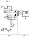
- FIG. 2 is a basic circuit diagram of the invention Measuring device shown, again those listed in Fig. 1 Windings are shown in a different representation.
- This transmission can be time division multiplex or frequency division multiplex happen in both directions.
- how from the auxiliary windings 2 and 3 of the stator Angle information about the angle of rotation ⁇ over one in one Low pass 6 lying frequency 7 of 10 kHz is coupled out.
- steering wheel information can, for example, the information from a sensor serve on the steering wheel or the switch position that in a steering wheel electronics converted into suitable frequency signals becomes. These signals can then be fed through the windings 2.3 of the stator and a bandpass 11 and a first Uncouple stator electronics 12 and either into the electronic Feed in the CAN network or directly to trigger Use actuators (horn, indicators, radio).
- In reverse Direction can 13 sensor information via a second stator electronics or information from the network CAN in for the Bandpass 9 suitable frequencies are implemented so that these Processed information about the steering wheel electronics 10 and thus for actuating suitable actuators (e.g. squib for airbag) can be evaluated.
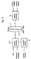
- Fig. 3 shows a further simplified representation of the Relationships according to Fig. 2.
- the power supply for the steering wheel electronics 10 also contactless the windings 1 to 5 of the resolver to the steering wheel can be.
- the number is also numerical of the parallel lines indicated.
- the central electronics and also parts of the resolver itself can be integrated into the steering column switch 15. Switching states can also be made via the central electronics the steering column switch 15 via the CAN bus to the chassis arranged electrical devices are transmitted.
Landscapes
- Engineering & Computer Science (AREA)
- Mechanical Engineering (AREA)
- Physics & Mathematics (AREA)
- General Physics & Mathematics (AREA)
- Chemical & Material Sciences (AREA)
- Combustion & Propulsion (AREA)
- Transportation (AREA)
- Transmission And Conversion Of Sensor Element Output (AREA)
- Measurement Of Length, Angles, Or The Like Using Electric Or Magnetic Means (AREA)
- Air Bags (AREA)
Description
- Fig. 1
- den prinzipiellen Aufbau eines Resolvers,
- Fig. 2
- in stark vereinfachter Darstellung den Aufbau der erfindungsgemäßen Meßeinrichtung mit zusätzlicher Übertragung von Informationssignalen,
- Fig. 3
- eine vereinfachte Darstellung der Schaltung nach Fig. 2,
- Fig. 4
- eine Prinzipskizze zur zeitmultiplexen Übertragung von Signalen und
- Fig. 5
- eine Prinzipskizze zur frequenzmultiplexen Übertragung von Signalen bei der erfindungsgemäßen Meßeinrichtung.
Claims (5)
- Meßeinrichtung zur Messung des Lenkwinkels α eines Fahrzeugs, dadurch gekennzeichnet, daß die Rotorwicklung (5) eines Resolvers mit der Lenksäule eines Fahrzeugs gekoppelt ist und die zur Bestimmung des Lenkwinkels dienenden Ausgangssignale des Resolvers an der ortsfesten Sekundärwicklung (2,3) des Resolvers abgegriffen werden.
- Meßeinrichtung nach Anspruch 1, dadurch gekennzeichnet, daß mit dem Lenkrad eine elektrische Einrichtung verbunden ist, die von einer chassisfesten Stromquelle und/oder Steuereinrichtung mit Signalen zur Energieversorgung bzw. Betätigung versorgt wird oder welche derartige Signale abgibt und daß die Einrichtung mit Anschlüssen der Rotorwicklung des Resolvers verbunden ist.
- Meßeinrichtung nach Anspruch 2, dadurch gekennzeichnet, daß die Einspeisesignale (f0, 10 kHZ) zum Betrieb des Resolvers als zur Winkelmesser- (α) und/oder Betriebssignale zur Erzielung der Versorgungs- bzw. Betätigungssignale in die Primärwicklung (1) im Zeitmultiplex oder Frequenzmultiplex (parallel durch Filterschaltung (6,9,11)) voneinander getrennte Kanäle in die Primärwicklung (1) des Resolvers eingespeist werden.
- Meßeinrichtung nach einem der Ansprüche 1 bis 3, dadurch gekennzeichnet, daß es sich bei der elektrischen Einrichtung um eine Auslöseschaltung eines Airbag oder Steuerschaltungen zur Einschaltung von elektrischen Geräten wie Autohupe, Radio oder Fahrzeugleuchten handelt.
- Meßeinrichtung nach einem der vorangegangenen Ansprüche, dadurch gekennzeichnet, daß zur berührungslosen Übertragung von Steuersignalen zwischen Lenkrad und entsprechenden chassisfesten Geräten Codierschaltungen bzw. Decodierschaltungen vorgesehen sind, welche die über einen neben den Meßsignalen zu übertragenden, die entsprechende Betätigung auslösenden Informationssignale derart verschlüsseln bzw. entschlüsseln, daß über einen einzigen Kanal verschiedene Geräte betätigende Signale übertragbar sind.
Applications Claiming Priority (3)
| Application Number | Priority Date | Filing Date | Title |
|---|---|---|---|
| DE19652935A DE19652935B4 (de) | 1996-12-19 | 1996-12-19 | Mit einem Resolver versehene Meßeinrichtung zur Messung des Lenkwinkels eines Fahrzeugs |
| DE19652935 | 1996-12-19 | ||
| PCT/EP1997/005654 WO1998026973A1 (de) | 1996-12-19 | 1997-10-14 | Mit einem resolver versehene messeinrichtung zur messung des lenkwinkels eines fahrzeugs |
Publications (2)
| Publication Number | Publication Date |
|---|---|
| EP0944515A1 EP0944515A1 (de) | 1999-09-29 |
| EP0944515B1 true EP0944515B1 (de) | 2001-06-13 |
Family
ID=7815303
Family Applications (1)
| Application Number | Title | Priority Date | Filing Date |
|---|---|---|---|
| EP97911220A Expired - Lifetime EP0944515B1 (de) | 1996-12-19 | 1997-10-14 | Mit einem resolver versehene messeinrichtung zur messung des lenkwinkels eines fahrzeugs |
Country Status (4)
| Country | Link |
|---|---|
| EP (1) | EP0944515B1 (de) |
| JP (1) | JP2001506557A (de) |
| DE (2) | DE19652935B4 (de) |
| WO (1) | WO1998026973A1 (de) |
Families Citing this family (8)
| Publication number | Priority date | Publication date | Assignee | Title |
|---|---|---|---|---|
| DE19946934B4 (de) * | 1999-09-30 | 2011-09-29 | Ramsle Technology Group Gmbh, Llc | Modul mit Winkelsensorik, berührungsloser Energieübertragung und berührungsloser Informationsübertragung |
| FR2800750B1 (fr) | 1999-11-05 | 2003-01-31 | Centre Nat Rech Scient | Proteines membranaires ctl (choline transporter like) impliquees dans le transport de la choline |
| DE10064510A1 (de) * | 2000-12-22 | 2002-07-04 | Valeo Schalter & Sensoren Gmbh | Schalteinrichtung |
| DE10158223B4 (de) * | 2001-11-16 | 2017-10-05 | Dr. Johannes Heidenhain Gmbh | Drehwinkel-Messgerät |
| US7057399B2 (en) | 2004-03-15 | 2006-06-06 | Visteon Global Technologies, Inc. | Resolver circuit including BTL amplifier |
| DE102015109418A1 (de) * | 2015-06-12 | 2016-12-15 | Sick Ag | Vorrichtung zur kontaktlosen Übertragung von Daten und zur Ermittlung einer Winkeländerung zwischen zwei sich relativ zueinander bewegenden Gegenständen |
| DE102015121432A1 (de) * | 2015-12-09 | 2017-06-14 | Sick Ag | Vorrichtung zur kontaktlosen Übertragung von Daten und zur Ermittlung einer Winkeländerung zwischen zwei sich relativ zueinander bewegenden Gegenständen |
| DE102015121423A1 (de) * | 2015-12-09 | 2017-06-14 | Sick Ag | Vorrichtung zur kontaktlosen Übertragung von Daten und zur Ermittlung einer Winkeländerung zwischen zwei sich relativ zueinander bewegenden Gegenständen |
Family Cites Families (16)
| Publication number | Priority date | Publication date | Assignee | Title |
|---|---|---|---|---|
| JPS5733355A (en) * | 1980-08-06 | 1982-02-23 | Toshiba Corp | Digital speed detector |
| JPS5836742A (ja) * | 1981-08-26 | 1983-03-03 | Aisin Seiki Co Ltd | ステアリング操作ボードの電力および信号伝送装置 |
| JPS58142509A (ja) * | 1982-02-19 | 1983-08-24 | Hitachi Ltd | 回転部分を有する自動車部品への電源供給装置 |
| JPS6120815A (ja) * | 1984-07-09 | 1986-01-29 | Nippon Denso Co Ltd | 回転位置検出装置 |
| JPS62215802A (ja) * | 1986-03-18 | 1987-09-22 | Honda Motor Co Ltd | 変位検出装置 |
| JPS63214617A (ja) * | 1987-03-02 | 1988-09-07 | Omron Tateisi Electronics Co | 多回転絶対位置検出装置 |
| DE3903359A1 (de) * | 1989-02-05 | 1990-08-09 | Bayerische Motoren Werke Ag | Einrichtung zur bestimmung des lenkraddrehwinkels eines kraftfahrzeuges |
| US5019981A (en) * | 1989-03-09 | 1991-05-28 | Fuji Jukogyo Kabushiki Kaisha | Device and method for decreasing power consumption of a steering angle detecting system for vehicle |
| DE4101163C1 (en) * | 1991-01-17 | 1992-05-21 | Daimler-Benz Aktiengesellschaft, 7000 Stuttgart, De | Wire- and contactless command signal optical transmitter - has photoelectric transmitters, in addition to photoelectric receivers, secured to car chassis |
| DE4120650A1 (de) * | 1991-06-22 | 1992-12-24 | Kolbenschmidt Ag | Vorrichtung zur uebertragung von elektrischer energie und daten in kraftfahrzeugen |
| US5473237A (en) * | 1992-02-05 | 1995-12-05 | Asm Automation, Sensorik, Messtechnik Gmbh | Angle-position sensor for the absolute measurement of the angle of rotation over a plurality of revolutions |
| US5504427A (en) * | 1992-11-12 | 1996-04-02 | Nartron Corporation | Rotational position sensor having variable coupling transformer |
| DE4404816B4 (de) * | 1994-02-16 | 2005-08-25 | Siemens Restraint Systems Gmbh | Vorrichtung zur Übertragung von Energie und Daten zwischen der Fahrzeug- und der Lenkradseite von Kraftfahrzeugen |
| JP3100841B2 (ja) * | 1994-08-19 | 2000-10-23 | 株式会社東芝 | 回転位置検出装置及びその方法 |
| DE19513692C1 (de) * | 1995-04-11 | 1996-07-18 | Stegmann Max Antriebstech | Drehwinkelmeßsystem |
| DE29518443U1 (de) * | 1995-11-22 | 1996-01-18 | DODUCO GMBH + Co. Dr. Eugen Dürrwächter, 75181 Pforzheim | Einrichtung zur leitungsgebundenen, uni- oder bidirektionalen Übertragung von elektrischen Signalen zu einem Lenkrad eines Fahrzeuges |
-
1996
- 1996-12-19 DE DE19652935A patent/DE19652935B4/de not_active Expired - Fee Related
-
1997
- 1997-10-14 EP EP97911220A patent/EP0944515B1/de not_active Expired - Lifetime
- 1997-10-14 DE DE59703828T patent/DE59703828D1/de not_active Expired - Lifetime
- 1997-10-14 JP JP52721798A patent/JP2001506557A/ja not_active Ceased
- 1997-10-14 WO PCT/EP1997/005654 patent/WO1998026973A1/de not_active Ceased
Also Published As
| Publication number | Publication date |
|---|---|
| DE19652935A1 (de) | 1998-06-25 |
| JP2001506557A (ja) | 2001-05-22 |
| DE19652935B4 (de) | 2005-04-21 |
| DE59703828D1 (de) | 2001-07-19 |
| EP0944515A1 (de) | 1999-09-29 |
| WO1998026973A1 (de) | 1998-06-25 |
Similar Documents
| Publication | Publication Date | Title |
|---|---|---|
| EP2113742B2 (de) | Messvorrichtung mit Zwei-Kanal-Abtastung | |
| EP1193472B1 (de) | Verfahren und Vorrichtung zur Bestimmung der Absolutposition bei Weg- und Winkelgebern | |
| DE102019207070A1 (de) | Rotorpositionssensor und Lenksystem für ein Kraftfahrzeug mit einem Rotorpositionssensor | |
| EP1303762B1 (de) | Übermittlung von mehreren sensorsignalen (kraftfahrzeug) im strommultiplex | |
| EP2335028B1 (de) | Multiturn-drehgeber | |
| EP1238251A1 (de) | Vorrichtung zur messung des winkels und/oder der winkelgeschwindigkeit eines drehbaren körpers und/oder des auf ihn wirkenden drehmoments | |
| DE10060287A1 (de) | Vorrichtung zur Messung des Winkels und/oder der Winkelgeschwindigkeit eines drehbaren Körpers und/oder des auf ihn wirkenden Drehmoments | |
| EP0143354B1 (de) | Mehrstufiger Winkelkodierer | |
| WO1998009173A1 (de) | Anordnung zur erfassung des drehverhaltens eines rades | |
| EP0171612A1 (de) | Lagemesseinrichtung | |
| EP0970000A1 (de) | Lenkwinkelsensorsystem mit erhöhter redundanz | |
| DE102016105964A1 (de) | Verfahren zur Lenkwinkelermittlung in einem Lenksystem mit elektrischem Servomotor | |
| WO2001023243A1 (de) | Modul mit winkelsensorik, berührungsloser energieübertragung und berührungsloser informationsübertragung | |
| DE19652935B4 (de) | Mit einem Resolver versehene Meßeinrichtung zur Messung des Lenkwinkels eines Fahrzeugs | |
| EP1824689B1 (de) | Übertragungssystem für reifenzustandsgrössen | |
| EP1149012A1 (de) | Vorrichtung zum erfassen der winkelstellung des lenkrades eines kraftfahrzeugs | |
| DE10347117B4 (de) | Elektronische Schaltungsanordnung zum wahlweise Anschluss von Drehzahlsensoren, insbesondere bei Nutzfahrzeugen | |
| DE4115244C2 (de) | Winkelsensor zur Bestimmung der Drehlage einer Lenkwelle eines Kraftfahrzeugs | |
| EP0581932B1 (de) | Drehwinkelsensor zur absoluten drehwinkelmessung über mehrere umdrehungen | |
| DE2743661A1 (de) | Gleichstrommotor mit mehrphasiger staenderwicklung und durch winkelstellungsgeber gesteuerter elektronischer kommutierungseinrichtung | |
| WO1997049996A1 (de) | Anordnung zur berührungslosen induktiven übertragung elektrischer messgrössen und/oder elektrischer energie zwischen einem rotor und einem stator | |
| EP0126253A1 (de) | Handwerkzeugmaschine, insbesondere Bohrmaschine | |
| DE102018214601B4 (de) | System zum Erfassen der Position einer Lineareinheit eines Linearsystems | |
| DE102008034318B4 (de) | Anordnung zur Auswertung der Messwerte eines Messwertwandlers | |
| DE10354469B4 (de) | Vorrichtung zum Messen des Drehwinkels eines Drehkörpers |
Legal Events
| Date | Code | Title | Description |
|---|---|---|---|
| PUAI | Public reference made under article 153(3) epc to a published international application that has entered the european phase |
Free format text: ORIGINAL CODE: 0009012 |
|
| 17P | Request for examination filed |
Effective date: 19990512 |
|
| AK | Designated contracting states |
Kind code of ref document: A1 Designated state(s): DE FR GB SE |
|
| GRAG | Despatch of communication of intention to grant |
Free format text: ORIGINAL CODE: EPIDOS AGRA |
|
| GRAG | Despatch of communication of intention to grant |
Free format text: ORIGINAL CODE: EPIDOS AGRA |
|
| GRAH | Despatch of communication of intention to grant a patent |
Free format text: ORIGINAL CODE: EPIDOS IGRA |
|
| 17Q | First examination report despatched |
Effective date: 20001019 |
|
| RAP1 | Party data changed (applicant data changed or rights of an application transferred) |
Owner name: VALEO SCHALTER UND SENSOREN GMBH |
|
| GRAH | Despatch of communication of intention to grant a patent |
Free format text: ORIGINAL CODE: EPIDOS IGRA |
|
| GRAA | (expected) grant |
Free format text: ORIGINAL CODE: 0009210 |
|
| AK | Designated contracting states |
Kind code of ref document: B1 Designated state(s): DE FR GB SE |
|
| GBT | Gb: translation of ep patent filed (gb section 77(6)(a)/1977) |
Effective date: 20010614 |
|
| REF | Corresponds to: |
Ref document number: 59703828 Country of ref document: DE Date of ref document: 20010719 |
|
| ET | Fr: translation filed | ||
| REG | Reference to a national code |
Ref country code: GB Ref legal event code: IF02 |
|
| PLBE | No opposition filed within time limit |
Free format text: ORIGINAL CODE: 0009261 |
|
| STAA | Information on the status of an ep patent application or granted ep patent |
Free format text: STATUS: NO OPPOSITION FILED WITHIN TIME LIMIT |
|
| 26N | No opposition filed | ||
| PGFP | Annual fee paid to national office [announced via postgrant information from national office to epo] |
Ref country code: SE Payment date: 20080918 Year of fee payment: 12 |
|
| PGFP | Annual fee paid to national office [announced via postgrant information from national office to epo] |
Ref country code: FR Payment date: 20081031 Year of fee payment: 12 |
|
| PGFP | Annual fee paid to national office [announced via postgrant information from national office to epo] |
Ref country code: GB Payment date: 20081010 Year of fee payment: 12 |
|
| EUG | Se: european patent has lapsed | ||
| REG | Reference to a national code |
Ref country code: FR Ref legal event code: ST Effective date: 20100630 |
|
| PG25 | Lapsed in a contracting state [announced via postgrant information from national office to epo] |
Ref country code: FR Free format text: LAPSE BECAUSE OF NON-PAYMENT OF DUE FEES Effective date: 20091102 |
|
| PG25 | Lapsed in a contracting state [announced via postgrant information from national office to epo] |
Ref country code: GB Free format text: LAPSE BECAUSE OF NON-PAYMENT OF DUE FEES Effective date: 20091014 |
|
| PG25 | Lapsed in a contracting state [announced via postgrant information from national office to epo] |
Ref country code: SE Free format text: LAPSE BECAUSE OF NON-PAYMENT OF DUE FEES Effective date: 20091015 |
|
| PGFP | Annual fee paid to national office [announced via postgrant information from national office to epo] |
Ref country code: DE Payment date: 20161013 Year of fee payment: 20 |
|
| REG | Reference to a national code |
Ref country code: DE Ref legal event code: R071 Ref document number: 59703828 Country of ref document: DE |