EP0944514B1 - Improvements relating to power-assisted steering assemblies - Google Patents
Improvements relating to power-assisted steering assemblies Download PDFInfo
- Publication number
- EP0944514B1 EP0944514B1 EP97950265A EP97950265A EP0944514B1 EP 0944514 B1 EP0944514 B1 EP 0944514B1 EP 97950265 A EP97950265 A EP 97950265A EP 97950265 A EP97950265 A EP 97950265A EP 0944514 B1 EP0944514 B1 EP 0944514B1
- Authority
- EP
- European Patent Office
- Prior art keywords
- housing
- support member
- motor
- housing assembly
- assembly according
- Prior art date
- Legal status (The legal status is an assumption and is not a legal conclusion. Google has not performed a legal analysis and makes no representation as to the accuracy of the status listed.)
- Expired - Lifetime
Links
- 230000006872 improvement Effects 0.000 title description 3
- 230000000712 assembly Effects 0.000 title 1
- 238000000429 assembly Methods 0.000 title 1
- 230000005670 electromagnetic radiation Effects 0.000 claims description 12
- 239000002184 metal Substances 0.000 claims description 4
- 230000004888 barrier function Effects 0.000 claims description 3
- 238000005266 casting Methods 0.000 claims description 3
- 230000005855 radiation Effects 0.000 claims description 3
- 238000010276 construction Methods 0.000 description 4
- 239000000463 material Substances 0.000 description 4
- 230000008901 benefit Effects 0.000 description 3
- 239000004020 conductor Substances 0.000 description 2
- SXHLTVKPNQVZGL-UHFFFAOYSA-N 1,2-dichloro-3-(3-chlorophenyl)benzene Chemical compound ClC1=CC=CC(C=2C(=C(Cl)C=CC=2)Cl)=C1 SXHLTVKPNQVZGL-UHFFFAOYSA-N 0.000 description 1
- 238000001816 cooling Methods 0.000 description 1
- 230000000694 effects Effects 0.000 description 1
- 238000009434 installation Methods 0.000 description 1
- 238000002955 isolation Methods 0.000 description 1
- 238000012423 maintenance Methods 0.000 description 1
- 230000009467 reduction Effects 0.000 description 1
- 230000002787 reinforcement Effects 0.000 description 1
- 230000004044 response Effects 0.000 description 1
- 238000007789 sealing Methods 0.000 description 1
Images


Classifications
-
- B—PERFORMING OPERATIONS; TRANSPORTING
- B62—LAND VEHICLES FOR TRAVELLING OTHERWISE THAN ON RAILS
- B62D—MOTOR VEHICLES; TRAILERS
- B62D5/00—Power-assisted or power-driven steering
- B62D5/04—Power-assisted or power-driven steering electrical, e.g. using an electric servo-motor connected to, or forming part of, the steering gear
-
- B—PERFORMING OPERATIONS; TRANSPORTING
- B62—LAND VEHICLES FOR TRAVELLING OTHERWISE THAN ON RAILS
- B62D—MOTOR VEHICLES; TRAILERS
- B62D5/00—Power-assisted or power-driven steering
- B62D5/04—Power-assisted or power-driven steering electrical, e.g. using an electric servo-motor connected to, or forming part of, the steering gear
- B62D5/0403—Power-assisted or power-driven steering electrical, e.g. using an electric servo-motor connected to, or forming part of, the steering gear characterised by constructional features, e.g. common housing for motor and gear box
- B62D5/0406—Power-assisted or power-driven steering electrical, e.g. using an electric servo-motor connected to, or forming part of, the steering gear characterised by constructional features, e.g. common housing for motor and gear box including housing for electronic control unit
-
- H—ELECTRICITY
- H02—GENERATION; CONVERSION OR DISTRIBUTION OF ELECTRIC POWER
- H02K—DYNAMO-ELECTRIC MACHINES
- H02K11/00—Structural association of dynamo-electric machines with electric components or with devices for shielding, monitoring or protection
- H02K11/30—Structural association with control circuits or drive circuits
- H02K11/33—Drive circuits, e.g. power electronics
Definitions
- the invention relates to improvements in housings for electric power-assisted steering systems for vehicles of the kind comprising an electric motor connected through a gearbox to an output shaft operatively connected to a steering column of the vehicle.
- the invention relates to reduction in the susceptibility of an electrical system to electromagnetic noise.
- the electric motor is used to assist a driver of the vehicle in turning the steering column, by applying an assistance torque of the same sense as the torque applied by the driver, which makes it easier to turn the steering wheel, for example during parking.
- the motor is controlled by motor control circuitry and drive circuitry.
- the control circuitry is typically connected to a torque sensor associated with the steering column and adapted to provide a signal indicative of the torque demand by the driver.
- the motor drive circuitry is adapted to switch the motor drive currents between, for example, different phases in the motor under the control of the motor control circuitry. It typically comprises a plurality of high power transistors connected in a bridge as it must handle the relatively high currents demanded by the motor. The transistors are switched under the control of the control circuitry.
- Electric motors are known to be relatively strong sources of electromagnetic radiation which can cause interference problems with other electronic circuitry provided in the motor vehicle and, in particular with the control circuitry in the steering system. Furthermore, because of the limited choice of positions in which the steering system can be mounted within the increasingly cramped confines of a vehicle, it is often exposed to many other sources of electromagnetic radiation. External sources of radiation, such as overhead power lines, can also produce electromagnetic radiation which can cause interference. In a safety critical application such as a power-assisted steering system, it is important to provide a high level of shielding from this electromagnetic radiation to minimise the susceptibility of the electronic control and drive circuitry from interference.
- a housing assembly for an electric power-assisted steering system of the kind disclosed in the above mentioned document comprises the features defined in the characterising part of claim 1.
- the compartment is closed by a lid member to seal the inside of the compartment substantially from the outside of the compartment.
- the housing is a one-piece housing.
- the motor may comprise a part of the electrical power assisted steering system.
- An advantage of physically separating the two circuits (or electrical devices) is that the electromagnetic radiation emitted by one of the circuit is substantially shielded from the other circuit, reducing noise.
- electrical device should be given a broad interpretation to include, for example, an electronic circuit or other assembly of discrete electrical and electronic components or even a combination of electrical/electronic components and a primarily mechanical device such as an electrical motor.
- the housing may further comprise a second compartment which is part of a one-piece housing and is adapted to contain a motor that is electrically connected to the motor drive circuitry.
- An advantage of a one-piece housing is that there are less openings which may provide a passage for electromagnetic radiation between the two compartments, eliminating the rigorous requirements for sealing of openings.
- the benefits of this invention extend to systems other than electrical power steering systems where isolation is advantageous.
- the compartment containing the support member is closed by a lid portion.
- the support member may be adapted to form a seal with said one-piece housing to prevent electromagnetic radiation transmitting from one side of the support member to the other side of the support member and visa-versa.
- the support member may be adapted to be mounted onto a printed circuit board (PCB) which carries at least one of the drive circuitry and the control circuitry or both.
- PCB printed circuit board
- the support member is adapted to act as a heatsink.
- the support member may support parts of the drive circuitry e.g. the bridge transistors and or a regulator. This can help to eliminate the need for cooling vents in the housing or lid portion.
- the support member may be formed from any heat conducting material where it is to act as a heatsink. Metal may be used as this is a good conductor of heat.
- the support member may be formed as an integral part of a one-piece housing but be made from a different material to the housing (i.e. a casting with an insert).
- the drive circuitry for the motor (which carries a relatively high current) can be isolated from the control circuitry (which carries only low power signals). This helps to prevent electromagnetic radiation emitted by the high power components causing interference in the low power components.
- the support member may be formed as an integral part of the one-piece housing and not as a separate barrier. If it is an integral part, it could be formed from the same material as the remainder of the housing, or from a different material.
- the support member may be adapted to be bolted onto the housing through the PCB so as to support the PCB in place. Additionally, the portion of the one-piece housing containing the gearbox and the motor may also be divided into two chambers, one containing the gearbox, the other the motor.
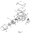
- Figure 1 shows an exploded view of an electric power assisted steering system.
- a one-piece housing 1 which accommodates, in one self contained unit, the various component parts of the power steering system, including a motor 12, a gearbox (not shown), a torque sensor 19 and the motor drive circuitry and control circuitry.
- the housing 1 is of a one piece construction and in the embodiment shown is cast from metal.
- the housing 1 defines two separate compartments 2,3, one disposed above the other.
- the lower component 3 has an upper internal face (not shown) and lower external face (not shown) and a first 4a,4b and second pair 5a,5b of orthogonal external walls.
- the upper compartment has a lower internal face 6 which is formed from the same part of the housing which carries the upper face of the lower compartment, and two pairs of orthogonal walls, 8a,8b,7a,7b.
- the upper compartment 2 has no internal upper face. Instead, a removable lid 28 is provided.
- a substantially circular opening 9a,9b is provided in each of the first pair of orthogonal walls 4a,4b of the lower compartment of the housing.
- a steering column (not shown) of a vehicle is adapted to extend sealingly into the lower compartment 3 through these two openings 9a,9b.
- a further opening 10 is provided in one of the second pair of orthogonal walls 5a,5b of the lower compartment and is surrounded by a cylindrical shroud 11 which projects axially away from the opening 10 outside of the lower compartment 3.
- the motor assembly 12 which comprises a rotor 13 and a stator 14 is mounted inside the shroud 11. This eliminates the need for a separate motor casing.
- An end cap 15 is placed over the motor assembly 12 to form a seal at the end of the shroud 11 distal from the main housing 1. With the steering column and the motor in place, the inside of the lower compartment 3 is sealed from the outside environment.
- the motor rotor 13 is secured to a spindle 16 which extends through the motor stator and projects into the lower compartment 3.
- the motor rotor 13 is adapted to drive the steering column through a worm gear and worm wheel which defines a gearset (not shown).
- a small opening is provided inside the shroud 11 extending into the upper compartment 2 to allow electrical connections from the motor assembly 12 to pass through into the upper compartment 2.
- the opening 17 also allows electrical connections 18 from a motor rotor position sensor (not shown) provided as a part of the motor assembly to pass through.
- a recess is formed around one of the openings 9a in the first pair of orthogonal walls 4a,4b of the lower compartment 2.
- a torque sensor 19 is provided inside this recess in the form of an annular assembly which is adapted to fit around a portion of the steering column shaft where it extends through the opening 9a. Electrical connections 21 to and from the torque sensor 19 are adapted to extend through an opening 32 provided in the wall of the upper compartment 2 directly above the opening 9a.
- the torque sensor 19 is adapted to provide an output signal indicative of the torque demand input by the driver of the vehicle to the steering column.
- This output signal is connected to a motor control circuitry which is adapted to control the motor in response to motor position signals, steering column torque signals and vehicle speed signals etc.
- the control circuitry provides a control signal to the motor drive circuitry which operates the motor to apply a torque to the steering column so as to assist the driver.
- the motor drive circuitry and control circuitry is disposed in the upper compartment 2 as shown in Figure 4. This is advantageous as the electronic circuitry is thereby well shielded from the electric motor 12 which is sealed within the lower compartment 3. Furthermore, when the lid 28 is secured on the upper face of the side walls 7a,7b,8a,8b of the upper compartment 2, the electronic circuitry is also, well protected from any external electromagnetic energy sources.
- the motor drive circuitry and motor control circuitry is mounted onto a printed circuit board 20.
- the circuitry is mounted onto the PCB 20 prior to installing the electronic circuitry within the upper compartment 2.
- the various electronic components are separated on the PCB so that the high power components (such as the motor drive circuitry transistors) are disposed on one half of the circuit board.
- the more sensitive electronic components, such as the motor control circuitry, are disposed on the other half of the circuit board.
- a metal (or other material) support member 21 is fixed on to one side of the circuit board across the centre of the board so as to separate physically the high power and lower power components.
- the support member 21 provides additional rigidity to the circuit board 20, and also performs the function of a heatsink for the motor drive transistors 25 of the drive circuitry, as shown in Figure 5. Additionally, the support member 21 can also act as a heatsink for any other kind of device which requires heatsinking, for example, a regulator 26 as shown in Figures 5(a) and 5(b).
- the support member 21 forms a seal with the lower face 6 and sides 7a,7b,8a,8b of the upper compartment 2, effectively dividing the compartment 2 into subcompartments 22,23 which are electromagnetically shielded from one another.
- this construction provides good electromagnetic compatibility (EMC) by shielding the components which may be susceptible to noise from the high power circuitry and the electric motor. Furthermore, this construction results in a minimum number of seals which are a potential source of leakage of electromagnetic radiation.
- the present invention lies in the alleviation of the effects of electromagnetic radiation on the electronic circuitry in an electric power assisted steering system by reducing the number of seals and other potential sources of leakage in the housing design. Furthermore, the inventors have appreciated that significant improvement can be made by physically separating the sensitive control circuitry from the high power drive circuitry and the relatively noisy electric motor.
Landscapes
- Engineering & Computer Science (AREA)
- Chemical & Material Sciences (AREA)
- Combustion & Propulsion (AREA)
- Transportation (AREA)
- Mechanical Engineering (AREA)
- Microelectronics & Electronic Packaging (AREA)
- Power Engineering (AREA)
- Power Steering Mechanism (AREA)
- Steering Controls (AREA)
Description
Claims (11)
- A housing assembly for an electric power-assisted steering system of the kind in which an electric motor (12) is connected through a gearbox to an output shaft operatively connected to a steering column for a vehicle, the housing defining at least two discrete compartments (2, 3), a first one of the compartments (3) being adapted to house the gearbox, and a second one of the compartments (2) being adapted to house a motor control circuit, characterised in that the housing for the gearbox also houses the motor whilst the other houses a motor drive circuit, a support member (21) being adapted to provide a physical barrier between the drive circuit and the control circuit, and in which the support member (21) is adapted to form a seal with said housing (1) substantially to prevent electromagnetic radiation transmitting from one side of the support member (21) to the other side of the support member.
- A housing assembly according to claim 1, characterised in that the second compartment (2) of the one-piece housing containing the gearbox and the motor is divided into two chambers, a first chamber containing the gearbox and a second chamber containing the motor.
- A housing assembly according to any preceding claim, characterised in that the housing comprises a one-piece casting.
- A housing assembly according to any preceding claim in which the housing and support member comprise an integral component with the support member being made as an insert in a casting which forms the housing.
- A housing assembly (1) according to any preceding claim, characterised in that the compartment is closed by a lid portion.
- A housing assembly (1) according to any preceding claim, characterised in that the support member (21) is adapted to be mounted onto a printed circuit board (20) which carries at least one of the first electrical adapted to emit electromagnetic radiation and the second electrical component which is sensitive to said radiation.
- A housing assembly according to any preceding claim, characterised in that the support member (21) is adapted to act as a heat sink.
- A housing assembly according to any preceding claim, characterised in that the support member (21) supports parts of the electrical circuit.
- A housing assembly according to any preceding claim, characterised in that the support member (21) is made of metal.
- A housing assembly according to any preceding claim, characterised in that the support member (21) is formed as an integral part of the one-piece housing (1).
- A housing assembly for an electrical device according to any one of claims 1 to 9, characterised in that the support member (21) is adapted to be mounted onto the housing (1) through the printed circuit board (20) so as to substantially support the printed circuit board in place.
Applications Claiming Priority (3)
| Application Number | Priority Date | Filing Date | Title |
|---|---|---|---|
| GBGB9626298.5A GB9626298D0 (en) | 1996-12-19 | 1996-12-19 | Improvements relating to powder-assisted steering assemblies |
| GB9626298 | 1996-12-19 | ||
| PCT/GB1997/003475 WO1998026972A1 (en) | 1996-12-19 | 1997-12-18 | Improvements relating to power-assisted steering assemblies |
Publications (2)
| Publication Number | Publication Date |
|---|---|
| EP0944514A1 EP0944514A1 (en) | 1999-09-29 |
| EP0944514B1 true EP0944514B1 (en) | 2001-10-04 |
Family
ID=10804646
Family Applications (1)
| Application Number | Title | Priority Date | Filing Date |
|---|---|---|---|
| EP97950265A Expired - Lifetime EP0944514B1 (en) | 1996-12-19 | 1997-12-18 | Improvements relating to power-assisted steering assemblies |
Country Status (9)
| Country | Link |
|---|---|
| US (1) | US6107716A (en) |
| EP (1) | EP0944514B1 (en) |
| JP (1) | JP4262777B2 (en) |
| KR (1) | KR100548124B1 (en) |
| BR (1) | BR9713965A (en) |
| DE (1) | DE69707151T2 (en) |
| ES (1) | ES2162338T3 (en) |
| GB (1) | GB9626298D0 (en) |
| WO (1) | WO1998026972A1 (en) |
Cited By (1)
| Publication number | Priority date | Publication date | Assignee | Title |
|---|---|---|---|---|
| EP4535627A4 (en) * | 2022-05-25 | 2025-08-06 | Nissan Motor | DRIVE DEVICE |
Families Citing this family (36)
| Publication number | Priority date | Publication date | Assignee | Title |
|---|---|---|---|---|
| GB9824590D0 (en) * | 1998-11-11 | 1999-01-06 | Trw Lucas Varity Electric | Improvements relating to power steering |
| US6297572B1 (en) | 1999-08-24 | 2001-10-02 | Calsonic Kansei Corporation | Brushless motor |
| EP1130745A3 (en) * | 2000-03-02 | 2003-12-10 | Calsonic Kansei Corporation | Brushless motor |
| JP3774624B2 (en) * | 2000-10-18 | 2006-05-17 | 三菱電機株式会社 | Electric power steering device |
| US6662897B2 (en) * | 2001-06-15 | 2003-12-16 | Nsk Ltd. | Electric power steering apparatus |
| US6695091B2 (en) | 2001-08-28 | 2004-02-24 | Trw Inc. | Electric steering motor with internal circuit board |
| JP2003164112A (en) * | 2001-11-20 | 2003-06-06 | Mitsubishi Electric Corp | Motor with inverter |
| JP3593102B2 (en) * | 2002-01-08 | 2004-11-24 | 三菱電機株式会社 | Electric power steering device |
| JP3997855B2 (en) * | 2002-07-15 | 2007-10-24 | 株式会社豊田自動織機 | Electric compressor |
| US6851509B2 (en) * | 2002-08-09 | 2005-02-08 | Denso Corporation | Easy-to-assemble structure of electric power steering device |
| JP4085828B2 (en) * | 2003-01-31 | 2008-05-14 | 株式会社ジェイテクト | Torque detection device |
| JP4144364B2 (en) | 2003-01-31 | 2008-09-03 | 株式会社ジェイテクト | Torque detection device |
| JP4161074B2 (en) * | 2004-02-02 | 2008-10-08 | 三菱電機株式会社 | Electric power steering device |
| EP2233901A1 (en) * | 2004-04-08 | 2010-09-29 | Jtekt Corporation | Torque detecting apparatus and manufacturing method thereof |
| US7017689B2 (en) * | 2004-05-06 | 2006-03-28 | Crown Equipment Corporation | Electrical steering assist for material handling vehicles |
| US7663274B2 (en) * | 2004-09-21 | 2010-02-16 | Nidec Corporation | Motor |
| DE202004015038U1 (en) * | 2004-09-24 | 2005-11-10 | Dbt Gmbh | Drive device for mining extraction machines |
| AT7865U1 (en) * | 2004-09-23 | 2005-10-17 | Siemens Ag Oesterreich | ELECTROMECHANICAL ADJUSTING DEVICE FOR A TRANSMISSION OF A MOTOR VEHICLE |
| US7273357B2 (en) * | 2005-08-10 | 2007-09-25 | Mitsubishi Heavy Industries, Ltd. | Control device for electric compressor |
| JP4102404B2 (en) * | 2005-11-21 | 2008-06-18 | 三菱電機株式会社 | Electric power steering device |
| JP5473192B2 (en) * | 2006-01-25 | 2014-04-16 | 株式会社豊田自動織機 | Electric compressor |
| US7789191B2 (en) * | 2007-04-24 | 2010-09-07 | Sona Koyo Steering Systems Ltd. | Electric power assist module for steering system |
| JP2009132174A (en) * | 2007-11-28 | 2009-06-18 | Mitsubishi Electric Corp | Electric power steering device |
| US7923875B2 (en) * | 2008-04-25 | 2011-04-12 | A.O. Smith Corporation | Assembly for an electric machine |
| JP5107133B2 (en) * | 2008-05-14 | 2012-12-26 | 三菱重工業株式会社 | Inverter-integrated electric compressor |
| DE102009001419A1 (en) * | 2008-06-16 | 2009-12-17 | Robert Bosch Gmbh | Transmission drive unit and a method for producing such |
| DE102010024738A1 (en) * | 2010-06-23 | 2011-12-29 | Volkswagen Ag | Steering gear i.e. electromechanical steering gear, for passenger motor car, has interconnection formed as wireless plug connections between control device and rotational torque measurement unit and between control device and electromotor |
| EP2481654B1 (en) * | 2010-12-02 | 2016-05-11 | NSK Ltd. | Electric power steering device |
| US20130062137A1 (en) * | 2011-09-14 | 2013-03-14 | Hitachi Automotive Systems, Ltd. | Electric Power Steering System |
| US9373986B2 (en) * | 2012-11-02 | 2016-06-21 | Rockwell Automation Technologies, Inc. | Method for providing servo motor rear bearing support, space for internal electronic packaging and IP sealing between motor and externally attached devices |
| US9048708B2 (en) * | 2012-11-05 | 2015-06-02 | Rockwell Automation Technologies, Inc. | Integrated drive-motor assembly with IP seal and enhanced heat transfer |
| DE112014001300T5 (en) | 2013-03-14 | 2016-01-07 | Crown Equipment Corporation | Electric steering assistance for a transport vehicle or industrial truck |
| KR102465340B1 (en) * | 2016-02-05 | 2022-11-11 | 에이치엘만도 주식회사 | Steering apparatus for vehicle |
| CN117294083A (en) * | 2022-06-20 | 2023-12-26 | 法雷奥西门子新能源汽车德国有限责任公司 | Electric drive assembly, vehicle and method for assembling an electric drive assembly |
| DE102022213251A1 (en) * | 2022-12-08 | 2024-06-13 | Zf Friedrichshafen Ag | Electric steering system and vehicle with the steering system |
| DE102024209715A1 (en) * | 2024-10-04 | 2026-04-09 | Robert Bosch Gesellschaft mit beschränkter Haftung | Electric motor-gearbox assembly |
Family Cites Families (8)
| Publication number | Priority date | Publication date | Assignee | Title |
|---|---|---|---|---|
| GB2101811B (en) * | 1981-06-30 | 1985-01-03 | Racal Dana Instr Ltd | Improvements in and relating to the screening of electrical circuit arrangements |
| JPS5822760A (en) * | 1981-08-05 | 1983-02-10 | Nissan Motor Co Ltd | Steering force controller for power steering |
| JP2983405B2 (en) * | 1993-03-23 | 1999-11-29 | 三菱電機株式会社 | Electric power steering circuit device |
| JP3059059B2 (en) * | 1994-09-27 | 2000-07-04 | 本田技研工業株式会社 | Motor for power steering system |
| JP3604460B2 (en) * | 1995-06-14 | 2004-12-22 | 光洋精工株式会社 | Electric power steering device |
| JP3543041B2 (en) * | 1996-01-30 | 2004-07-14 | 光洋精工株式会社 | Electric power steering device |
| JP3336603B2 (en) * | 1996-11-05 | 2002-10-21 | トヨタ自動車株式会社 | Power steering device |
| JP3612161B2 (en) * | 1997-01-09 | 2005-01-19 | 株式会社ミツバ | Motor device with rotation detection mechanism |
-
1996
- 1996-12-19 GB GBGB9626298.5A patent/GB9626298D0/en active Pending
-
1997
- 1997-12-18 BR BR9713965-3A patent/BR9713965A/en not_active IP Right Cessation
- 1997-12-18 US US09/319,376 patent/US6107716A/en not_active Expired - Fee Related
- 1997-12-18 ES ES97950265T patent/ES2162338T3/en not_active Expired - Lifetime
- 1997-12-18 JP JP52746598A patent/JP4262777B2/en not_active Expired - Fee Related
- 1997-12-18 DE DE69707151T patent/DE69707151T2/en not_active Expired - Fee Related
- 1997-12-18 KR KR1019997005473A patent/KR100548124B1/en not_active Expired - Fee Related
- 1997-12-18 WO PCT/GB1997/003475 patent/WO1998026972A1/en not_active Ceased
- 1997-12-18 EP EP97950265A patent/EP0944514B1/en not_active Expired - Lifetime
Cited By (1)
| Publication number | Priority date | Publication date | Assignee | Title |
|---|---|---|---|---|
| EP4535627A4 (en) * | 2022-05-25 | 2025-08-06 | Nissan Motor | DRIVE DEVICE |
Also Published As
| Publication number | Publication date |
|---|---|
| US6107716A (en) | 2000-08-22 |
| KR100548124B1 (en) | 2006-02-02 |
| ES2162338T3 (en) | 2001-12-16 |
| GB9626298D0 (en) | 1997-02-05 |
| JP4262777B2 (en) | 2009-05-13 |
| WO1998026972A1 (en) | 1998-06-25 |
| JP2001506558A (en) | 2001-05-22 |
| BR9713965A (en) | 2000-04-11 |
| EP0944514A1 (en) | 1999-09-29 |
| KR20000057659A (en) | 2000-09-25 |
| DE69707151T2 (en) | 2002-06-27 |
| DE69707151D1 (en) | 2001-11-08 |
Similar Documents
| Publication | Publication Date | Title |
|---|---|---|
| US6107716A (en) | Power-assisted steering assemblies | |
| KR101788524B1 (en) | Electric Driving Device and Electric Power Steering Device | |
| JP5045439B2 (en) | Electric power steering device | |
| KR101788525B1 (en) | Electric Driving Device and Electric Power Steering Device | |
| EP0733536B1 (en) | Electric power steering device | |
| US9521775B2 (en) | Drive apparatus | |
| US9479025B2 (en) | Drive device and electric power steering device including the drive device | |
| CN110892614B (en) | Electric drive and electric power steering | |
| CN107921997A (en) | Electric drive and electric power steering | |
| JP2009214860A (en) | Vehicular steering device and method for transferring its sub assembly | |
| CN109964392B (en) | Electric drive and electric power steering | |
| US12562613B2 (en) | Electronic control device | |
| JP3309684B2 (en) | Motor drive | |
| JPH11115775A (en) | Electric power steering controller | |
| CN109643929B (en) | Electric drive and electric power steering | |
| KR20200035120A (en) | Electric drive and electric power steering | |
| JP2004153897A (en) | Electric machine with inverter | |
| JP2001106097A (en) | Electric steering device | |
| JP4952666B2 (en) | Electric power steering device | |
| JP2003341529A (en) | Electric power steering device | |
| JP7484646B2 (en) | Motor unit and electric power steering device | |
| EP4726977A1 (en) | Motor control apparatus, electrical power steering device, and vehicle | |
| JP7404915B2 (en) | Motor unit and electric power steering device | |
| JP2007106284A (en) | Electric power steering device |
Legal Events
| Date | Code | Title | Description |
|---|---|---|---|
| PUAI | Public reference made under article 153(3) epc to a published international application that has entered the european phase |
Free format text: ORIGINAL CODE: 0009012 |
|
| 17P | Request for examination filed |
Effective date: 19990713 |
|
| AK | Designated contracting states |
Kind code of ref document: A1 Designated state(s): DE ES FR GB IT |
|
| 17Q | First examination report despatched |
Effective date: 19991204 |
|
| GRAG | Despatch of communication of intention to grant |
Free format text: ORIGINAL CODE: EPIDOS AGRA |
|
| RAP1 | Party data changed (applicant data changed or rights of an application transferred) |
Owner name: TRW LUCASVARITY ELECTRIC STEERING LIMITED |
|
| GRAG | Despatch of communication of intention to grant |
Free format text: ORIGINAL CODE: EPIDOS AGRA |
|
| GRAH | Despatch of communication of intention to grant a patent |
Free format text: ORIGINAL CODE: EPIDOS IGRA |
|
| GRAH | Despatch of communication of intention to grant a patent |
Free format text: ORIGINAL CODE: EPIDOS IGRA |
|
| GRAA | (expected) grant |
Free format text: ORIGINAL CODE: 0009210 |
|
| AK | Designated contracting states |
Kind code of ref document: B1 Designated state(s): DE ES FR GB IT |
|
| REF | Corresponds to: |
Ref document number: 69707151 Country of ref document: DE Date of ref document: 20011108 |
|
| REG | Reference to a national code |
Ref country code: ES Ref legal event code: FG2A Ref document number: 2162338 Country of ref document: ES Kind code of ref document: T3 |
|
| REG | Reference to a national code |
Ref country code: GB Ref legal event code: IF02 |
|
| ET | Fr: translation filed | ||
| PLBE | No opposition filed within time limit |
Free format text: ORIGINAL CODE: 0009261 |
|
| STAA | Information on the status of an ep patent application or granted ep patent |
Free format text: STATUS: NO OPPOSITION FILED WITHIN TIME LIMIT |
|
| 26N | No opposition filed | ||
| REG | Reference to a national code |
Ref country code: GB Ref legal event code: 732E |
|
| REG | Reference to a national code |
Ref country code: GB Ref legal event code: 732E |
|
| PGFP | Annual fee paid to national office [announced via postgrant information from national office to epo] |
Ref country code: GB Payment date: 20061106 Year of fee payment: 10 |
|
| PGFP | Annual fee paid to national office [announced via postgrant information from national office to epo] |
Ref country code: ES Payment date: 20071211 Year of fee payment: 11 |
|
| PGFP | Annual fee paid to national office [announced via postgrant information from national office to epo] |
Ref country code: IT Payment date: 20071218 Year of fee payment: 11 |
|
| PGFP | Annual fee paid to national office [announced via postgrant information from national office to epo] |
Ref country code: DE Payment date: 20071228 Year of fee payment: 11 |
|
| GBPC | Gb: european patent ceased through non-payment of renewal fee |
Effective date: 20071218 |
|
| PG25 | Lapsed in a contracting state [announced via postgrant information from national office to epo] |
Ref country code: GB Free format text: LAPSE BECAUSE OF NON-PAYMENT OF DUE FEES Effective date: 20071218 |
|
| PGFP | Annual fee paid to national office [announced via postgrant information from national office to epo] |
Ref country code: FR Payment date: 20081205 Year of fee payment: 12 |
|
| PG25 | Lapsed in a contracting state [announced via postgrant information from national office to epo] |
Ref country code: DE Free format text: LAPSE BECAUSE OF NON-PAYMENT OF DUE FEES Effective date: 20090701 |
|
| REG | Reference to a national code |
Ref country code: ES Ref legal event code: FD2A Effective date: 20081219 |
|
| PG25 | Lapsed in a contracting state [announced via postgrant information from national office to epo] |
Ref country code: ES Free format text: LAPSE BECAUSE OF NON-PAYMENT OF DUE FEES Effective date: 20081219 |
|
| REG | Reference to a national code |
Ref country code: FR Ref legal event code: ST Effective date: 20100831 |
|
| PG25 | Lapsed in a contracting state [announced via postgrant information from national office to epo] |
Ref country code: FR Free format text: LAPSE BECAUSE OF NON-PAYMENT OF DUE FEES Effective date: 20091231 |
|
| PG25 | Lapsed in a contracting state [announced via postgrant information from national office to epo] |
Ref country code: IT Free format text: LAPSE BECAUSE OF NON-PAYMENT OF DUE FEES Effective date: 20081218 |