EP0944472B1 - Plastic molded part with a construction structure - Google Patents
Plastic molded part with a construction structure Download PDFInfo
- Publication number
- EP0944472B1 EP0944472B1 EP97941779A EP97941779A EP0944472B1 EP 0944472 B1 EP0944472 B1 EP 0944472B1 EP 97941779 A EP97941779 A EP 97941779A EP 97941779 A EP97941779 A EP 97941779A EP 0944472 B1 EP0944472 B1 EP 0944472B1
- Authority
- EP
- European Patent Office
- Prior art keywords
- structural elements
- polymer material
- load
- moulding
- bearing structure
- Prior art date
- Legal status (The legal status is an assumption and is not a legal conclusion. Google has not performed a legal analysis and makes no representation as to the accuracy of the status listed.)
- Revoked
Links
- 229920003023 plastic Polymers 0.000 title claims description 15
- 239000004033 plastic Substances 0.000 title claims description 15
- 238000010276 construction Methods 0.000 title description 18
- 239000002861 polymer material Substances 0.000 claims abstract description 29
- 238000000465 moulding Methods 0.000 claims abstract description 20
- 238000010137 moulding (plastic) Methods 0.000 claims abstract description 7
- 238000013461 design Methods 0.000 claims abstract description 4
- 229920000642 polymer Polymers 0.000 claims description 44
- 239000000835 fiber Substances 0.000 claims description 28
- 238000000034 method Methods 0.000 claims description 21
- 239000000463 material Substances 0.000 claims description 20
- 229920001169 thermoplastic Polymers 0.000 claims description 20
- -1 polypropylene Polymers 0.000 claims description 18
- 230000008569 process Effects 0.000 claims description 16
- 230000002787 reinforcement Effects 0.000 claims description 15
- 239000004743 Polypropylene Substances 0.000 claims description 10
- 239000011159 matrix material Substances 0.000 claims description 10
- 229920001707 polybutylene terephthalate Polymers 0.000 claims description 10
- 229920001155 polypropylene Polymers 0.000 claims description 10
- 241000264877 Hippospongia communis Species 0.000 claims description 8
- 239000004696 Poly ether ether ketone Substances 0.000 claims description 8
- 239000004952 Polyamide Substances 0.000 claims description 8
- 239000004642 Polyimide Substances 0.000 claims description 8
- 229920002647 polyamide Polymers 0.000 claims description 8
- 229920002530 polyetherether ketone Polymers 0.000 claims description 8
- 229920000139 polyethylene terephthalate Polymers 0.000 claims description 8
- 239000005020 polyethylene terephthalate Substances 0.000 claims description 8
- 229920001721 polyimide Polymers 0.000 claims description 8
- 239000004416 thermosoftening plastic Substances 0.000 claims description 8
- 238000001125 extrusion Methods 0.000 claims description 7
- 229920000515 polycarbonate Polymers 0.000 claims description 7
- 239000004417 polycarbonate Substances 0.000 claims description 7
- 238000001746 injection moulding Methods 0.000 claims description 5
- 229920002635 polyurethane Polymers 0.000 claims description 5
- 239000004814 polyurethane Substances 0.000 claims description 5
- OKTJSMMVPCPJKN-UHFFFAOYSA-N Carbon Chemical compound [C] OKTJSMMVPCPJKN-UHFFFAOYSA-N 0.000 claims description 4
- 229920000058 polyacrylate Polymers 0.000 claims description 4
- 230000003247 decreasing effect Effects 0.000 claims description 3
- 239000003822 epoxy resin Substances 0.000 claims description 3
- 239000011521 glass Substances 0.000 claims description 3
- 229920003986 novolac Polymers 0.000 claims description 3
- 229920000647 polyepoxide Polymers 0.000 claims description 3
- 229920003235 aromatic polyamide Polymers 0.000 claims description 2
- 229910052799 carbon Inorganic materials 0.000 claims description 2
- 238000006243 chemical reaction Methods 0.000 claims description 2
- 239000000109 continuous material Substances 0.000 claims description 2
- 238000005520 cutting process Methods 0.000 claims description 2
- 238000009792 diffusion process Methods 0.000 claims description 2
- LNEPOXFFQSENCJ-UHFFFAOYSA-N haloperidol Chemical compound C1CC(O)(C=2C=CC(Cl)=CC=2)CCN1CCCC(=O)C1=CC=C(F)C=C1 LNEPOXFFQSENCJ-UHFFFAOYSA-N 0.000 claims description 2
- 229920001568 phenolic resin Polymers 0.000 claims description 2
- 239000005011 phenolic resin Substances 0.000 claims description 2
- 229920005989 resin Polymers 0.000 claims description 2
- 239000011347 resin Substances 0.000 claims description 2
- 238000003466 welding Methods 0.000 claims description 2
- 229920000265 Polyparaphenylene Polymers 0.000 claims 2
- UCKMPCXJQFINFW-UHFFFAOYSA-N Sulphide Chemical compound [S-2] UCKMPCXJQFINFW-UHFFFAOYSA-N 0.000 claims 2
- 241000531908 Aramides Species 0.000 claims 1
- 238000003801 milling Methods 0.000 claims 1
- 125000002924 primary amino group Chemical group [H]N([H])* 0.000 claims 1
- 230000037452 priming Effects 0.000 claims 1
- 238000004080 punching Methods 0.000 claims 1
- 229920006305 unsaturated polyester Polymers 0.000 claims 1
- 238000004519 manufacturing process Methods 0.000 description 13
- 229920001187 thermosetting polymer Polymers 0.000 description 9
- 230000003014 reinforcing effect Effects 0.000 description 6
- 239000007788 liquid Substances 0.000 description 5
- 239000004734 Polyphenylene sulfide Substances 0.000 description 4
- 238000005265 energy consumption Methods 0.000 description 4
- 238000002347 injection Methods 0.000 description 4
- 239000007924 injection Substances 0.000 description 4
- 229920000069 polyphenylene sulfide Polymers 0.000 description 4
- 229920000049 Carbon (fiber) Polymers 0.000 description 3
- 229920002430 Fibre-reinforced plastic Polymers 0.000 description 3
- 230000008901 benefit Effects 0.000 description 3
- 230000015572 biosynthetic process Effects 0.000 description 3
- 239000004917 carbon fiber Substances 0.000 description 3
- 239000011151 fibre-reinforced plastic Substances 0.000 description 3
- 239000002991 molded plastic Substances 0.000 description 3
- 229920000728 polyester Polymers 0.000 description 3
- 239000012815 thermoplastic material Substances 0.000 description 3
- WKBPZYKAUNRMKP-UHFFFAOYSA-N 1-[2-(2,4-dichlorophenyl)pentyl]1,2,4-triazole Chemical compound C=1C=C(Cl)C=C(Cl)C=1C(CCC)CN1C=NC=N1 WKBPZYKAUNRMKP-UHFFFAOYSA-N 0.000 description 2
- 238000004026 adhesive bonding Methods 0.000 description 2
- 238000000137 annealing Methods 0.000 description 2
- 239000004760 aramid Substances 0.000 description 2
- 238000005266 casting Methods 0.000 description 2
- 238000010586 diagram Methods 0.000 description 2
- 238000005516 engineering process Methods 0.000 description 2
- 239000006260 foam Substances 0.000 description 2
- 239000002828 fuel tank Substances 0.000 description 2
- 239000003365 glass fiber Substances 0.000 description 2
- 238000010348 incorporation Methods 0.000 description 2
- 239000003973 paint Substances 0.000 description 2
- 238000010422 painting Methods 0.000 description 2
- 239000012783 reinforcing fiber Substances 0.000 description 2
- 239000004616 structural foam Substances 0.000 description 2
- 239000011031 topaz Substances 0.000 description 2
- 229910052853 topaz Inorganic materials 0.000 description 2
- 238000004804 winding Methods 0.000 description 2
- 239000004698 Polyethylene Substances 0.000 description 1
- 229910000831 Steel Inorganic materials 0.000 description 1
- NIXOWILDQLNWCW-UHFFFAOYSA-N acrylic acid group Chemical group C(C=C)(=O)O NIXOWILDQLNWCW-UHFFFAOYSA-N 0.000 description 1
- 239000000654 additive Substances 0.000 description 1
- 229920003180 amino resin Polymers 0.000 description 1
- 229920006231 aramid fiber Polymers 0.000 description 1
- 230000009286 beneficial effect Effects 0.000 description 1
- 238000000071 blow moulding Methods 0.000 description 1
- 238000003490 calendering Methods 0.000 description 1
- 230000008859 change Effects 0.000 description 1
- 239000011248 coating agent Substances 0.000 description 1
- 238000000576 coating method Methods 0.000 description 1
- 238000007596 consolidation process Methods 0.000 description 1
- 238000009749 continuous casting Methods 0.000 description 1
- 239000011199 continuous fiber reinforced thermoplastic Substances 0.000 description 1
- 230000007797 corrosion Effects 0.000 description 1
- 238000005260 corrosion Methods 0.000 description 1
- 230000008878 coupling Effects 0.000 description 1
- 238000010168 coupling process Methods 0.000 description 1
- 238000005859 coupling reaction Methods 0.000 description 1
- 230000007423 decrease Effects 0.000 description 1
- 230000001419 dependent effect Effects 0.000 description 1
- 238000011161 development Methods 0.000 description 1
- 230000018109 developmental process Effects 0.000 description 1
- 230000000694 effects Effects 0.000 description 1
- 239000004744 fabric Substances 0.000 description 1
- 230000002349 favourable effect Effects 0.000 description 1
- 239000011152 fibreglass Substances 0.000 description 1
- 239000000446 fuel Substances 0.000 description 1
- JEIPFZHSYJVQDO-UHFFFAOYSA-N iron(III) oxide Inorganic materials O=[Fe]O[Fe]=O JEIPFZHSYJVQDO-UHFFFAOYSA-N 0.000 description 1
- 238000005304 joining Methods 0.000 description 1
- 238000002844 melting Methods 0.000 description 1
- 230000008018 melting Effects 0.000 description 1
- 239000002184 metal Substances 0.000 description 1
- 239000007769 metal material Substances 0.000 description 1
- 239000000178 monomer Substances 0.000 description 1
- 229920000573 polyethylene Polymers 0.000 description 1
- 229920002959 polymer blend Polymers 0.000 description 1
- 229920005594 polymer fiber Polymers 0.000 description 1
- 229920005606 polypropylene copolymer Polymers 0.000 description 1
- 229920005749 polyurethane resin Polymers 0.000 description 1
- 230000035484 reaction time Effects 0.000 description 1
- 239000002689 soil Substances 0.000 description 1
- 238000005507 spraying Methods 0.000 description 1
- 239000010959 steel Substances 0.000 description 1
- 238000005728 strengthening Methods 0.000 description 1
- 239000000126 substance Substances 0.000 description 1
- 238000012360 testing method Methods 0.000 description 1
- 239000004753 textile Substances 0.000 description 1
- 229920006337 unsaturated polyester resin Polymers 0.000 description 1
- 229920002554 vinyl polymer Polymers 0.000 description 1
Images


Classifications
-
- B—PERFORMING OPERATIONS; TRANSPORTING
- B62—LAND VEHICLES FOR TRAVELLING OTHERWISE THAN ON RAILS
- B62D—MOTOR VEHICLES; TRAILERS
- B62D29/00—Superstructures, understructures, or sub-units thereof, characterised by the material thereof
- B62D29/04—Superstructures, understructures, or sub-units thereof, characterised by the material thereof predominantly of synthetic material
- B62D29/041—Understructures
-
- B—PERFORMING OPERATIONS; TRANSPORTING
- B29—WORKING OF PLASTICS; WORKING OF SUBSTANCES IN A PLASTIC STATE IN GENERAL
- B29C—SHAPING OR JOINING OF PLASTICS; SHAPING OF MATERIAL IN A PLASTIC STATE, NOT OTHERWISE PROVIDED FOR; AFTER-TREATMENT OF THE SHAPED PRODUCTS, e.g. REPAIRING
- B29C45/00—Injection moulding, i.e. forcing the required volume of moulding material through a nozzle into a closed mould; Apparatus therefor
- B29C45/14—Injection moulding, i.e. forcing the required volume of moulding material through a nozzle into a closed mould; Apparatus therefor incorporating preformed parts or layers, e.g. injection moulding around inserts or for coating articles
- B29C45/14631—Coating reinforcements
-
- B—PERFORMING OPERATIONS; TRANSPORTING
- B29—WORKING OF PLASTICS; WORKING OF SUBSTANCES IN A PLASTIC STATE IN GENERAL
- B29C—SHAPING OR JOINING OF PLASTICS; SHAPING OF MATERIAL IN A PLASTIC STATE, NOT OTHERWISE PROVIDED FOR; AFTER-TREATMENT OF THE SHAPED PRODUCTS, e.g. REPAIRING
- B29C45/00—Injection moulding, i.e. forcing the required volume of moulding material through a nozzle into a closed mould; Apparatus therefor
- B29C45/16—Making multilayered or multicoloured articles
- B29C45/1671—Making multilayered or multicoloured articles with an insert
-
- B—PERFORMING OPERATIONS; TRANSPORTING
- B29—WORKING OF PLASTICS; WORKING OF SUBSTANCES IN A PLASTIC STATE IN GENERAL
- B29C—SHAPING OR JOINING OF PLASTICS; SHAPING OF MATERIAL IN A PLASTIC STATE, NOT OTHERWISE PROVIDED FOR; AFTER-TREATMENT OF THE SHAPED PRODUCTS, e.g. REPAIRING
- B29C65/00—Joining or sealing of preformed parts, e.g. welding of plastics materials; Apparatus therefor
- B29C65/70—Joining or sealing of preformed parts, e.g. welding of plastics materials; Apparatus therefor by moulding
-
- B—PERFORMING OPERATIONS; TRANSPORTING
- B29—WORKING OF PLASTICS; WORKING OF SUBSTANCES IN A PLASTIC STATE IN GENERAL
- B29C—SHAPING OR JOINING OF PLASTICS; SHAPING OF MATERIAL IN A PLASTIC STATE, NOT OTHERWISE PROVIDED FOR; AFTER-TREATMENT OF THE SHAPED PRODUCTS, e.g. REPAIRING
- B29C66/00—General aspects of processes or apparatus for joining preformed parts
- B29C66/01—General aspects dealing with the joint area or with the area to be joined
- B29C66/05—Particular design of joint configurations
- B29C66/10—Particular design of joint configurations particular design of the joint cross-sections
- B29C66/11—Joint cross-sections comprising a single joint-segment, i.e. one of the parts to be joined comprising a single joint-segment in the joint cross-section
- B29C66/112—Single lapped joints
- B29C66/1122—Single lap to lap joints, i.e. overlap joints
-
- B—PERFORMING OPERATIONS; TRANSPORTING
- B29—WORKING OF PLASTICS; WORKING OF SUBSTANCES IN A PLASTIC STATE IN GENERAL
- B29C—SHAPING OR JOINING OF PLASTICS; SHAPING OF MATERIAL IN A PLASTIC STATE, NOT OTHERWISE PROVIDED FOR; AFTER-TREATMENT OF THE SHAPED PRODUCTS, e.g. REPAIRING
- B29C66/00—General aspects of processes or apparatus for joining preformed parts
- B29C66/01—General aspects dealing with the joint area or with the area to be joined
- B29C66/05—Particular design of joint configurations
- B29C66/10—Particular design of joint configurations particular design of the joint cross-sections
- B29C66/11—Joint cross-sections comprising a single joint-segment, i.e. one of the parts to be joined comprising a single joint-segment in the joint cross-section
- B29C66/114—Single butt joints
- B29C66/1142—Single butt to butt joints
-
- B—PERFORMING OPERATIONS; TRANSPORTING
- B29—WORKING OF PLASTICS; WORKING OF SUBSTANCES IN A PLASTIC STATE IN GENERAL
- B29C—SHAPING OR JOINING OF PLASTICS; SHAPING OF MATERIAL IN A PLASTIC STATE, NOT OTHERWISE PROVIDED FOR; AFTER-TREATMENT OF THE SHAPED PRODUCTS, e.g. REPAIRING
- B29C66/00—General aspects of processes or apparatus for joining preformed parts
- B29C66/50—General aspects of joining tubular articles; General aspects of joining long products, i.e. bars or profiled elements; General aspects of joining single elements to tubular articles, hollow articles or bars; General aspects of joining several hollow-preforms to form hollow or tubular articles
- B29C66/51—Joining tubular articles, profiled elements or bars; Joining single elements to tubular articles, hollow articles or bars; Joining several hollow-preforms to form hollow or tubular articles
- B29C66/52—Joining tubular articles, bars or profiled elements
- B29C66/522—Joining tubular articles
- B29C66/5224—Joining tubular articles for forming fork-shaped connections, e.g. for making Y-shaped pieces
- B29C66/52241—Joining tubular articles for forming fork-shaped connections, e.g. for making Y-shaped pieces with two right angles, e.g. for making T-shaped pieces
-
- B—PERFORMING OPERATIONS; TRANSPORTING
- B29—WORKING OF PLASTICS; WORKING OF SUBSTANCES IN A PLASTIC STATE IN GENERAL
- B29C—SHAPING OR JOINING OF PLASTICS; SHAPING OF MATERIAL IN A PLASTIC STATE, NOT OTHERWISE PROVIDED FOR; AFTER-TREATMENT OF THE SHAPED PRODUCTS, e.g. REPAIRING
- B29C66/00—General aspects of processes or apparatus for joining preformed parts
- B29C66/50—General aspects of joining tubular articles; General aspects of joining long products, i.e. bars or profiled elements; General aspects of joining single elements to tubular articles, hollow articles or bars; General aspects of joining several hollow-preforms to form hollow or tubular articles
- B29C66/51—Joining tubular articles, profiled elements or bars; Joining single elements to tubular articles, hollow articles or bars; Joining several hollow-preforms to form hollow or tubular articles
- B29C66/52—Joining tubular articles, bars or profiled elements
- B29C66/522—Joining tubular articles
- B29C66/5225—Joining tubular articles for forming cross-shaped connections, e.g. for making X-shaped pieces
-
- B—PERFORMING OPERATIONS; TRANSPORTING
- B29—WORKING OF PLASTICS; WORKING OF SUBSTANCES IN A PLASTIC STATE IN GENERAL
- B29C—SHAPING OR JOINING OF PLASTICS; SHAPING OF MATERIAL IN A PLASTIC STATE, NOT OTHERWISE PROVIDED FOR; AFTER-TREATMENT OF THE SHAPED PRODUCTS, e.g. REPAIRING
- B29C66/00—General aspects of processes or apparatus for joining preformed parts
- B29C66/50—General aspects of joining tubular articles; General aspects of joining long products, i.e. bars or profiled elements; General aspects of joining single elements to tubular articles, hollow articles or bars; General aspects of joining several hollow-preforms to form hollow or tubular articles
- B29C66/51—Joining tubular articles, profiled elements or bars; Joining single elements to tubular articles, hollow articles or bars; Joining several hollow-preforms to form hollow or tubular articles
- B29C66/52—Joining tubular articles, bars or profiled elements
- B29C66/522—Joining tubular articles
- B29C66/5229—Joining tubular articles involving the use of a socket
-
- B—PERFORMING OPERATIONS; TRANSPORTING
- B29—WORKING OF PLASTICS; WORKING OF SUBSTANCES IN A PLASTIC STATE IN GENERAL
- B29C—SHAPING OR JOINING OF PLASTICS; SHAPING OF MATERIAL IN A PLASTIC STATE, NOT OTHERWISE PROVIDED FOR; AFTER-TREATMENT OF THE SHAPED PRODUCTS, e.g. REPAIRING
- B29C66/00—General aspects of processes or apparatus for joining preformed parts
- B29C66/50—General aspects of joining tubular articles; General aspects of joining long products, i.e. bars or profiled elements; General aspects of joining single elements to tubular articles, hollow articles or bars; General aspects of joining several hollow-preforms to form hollow or tubular articles
- B29C66/51—Joining tubular articles, profiled elements or bars; Joining single elements to tubular articles, hollow articles or bars; Joining several hollow-preforms to form hollow or tubular articles
- B29C66/52—Joining tubular articles, bars or profiled elements
- B29C66/524—Joining profiled elements
- B29C66/5244—Joining profiled elements for forming fork-shaped connections, e.g. for making window frames or Y-shaped pieces
- B29C66/52441—Joining profiled elements for forming fork-shaped connections, e.g. for making window frames or Y-shaped pieces with two right angles, e.g. for making T-shaped pieces
-
- B—PERFORMING OPERATIONS; TRANSPORTING
- B29—WORKING OF PLASTICS; WORKING OF SUBSTANCES IN A PLASTIC STATE IN GENERAL
- B29C—SHAPING OR JOINING OF PLASTICS; SHAPING OF MATERIAL IN A PLASTIC STATE, NOT OTHERWISE PROVIDED FOR; AFTER-TREATMENT OF THE SHAPED PRODUCTS, e.g. REPAIRING
- B29C66/00—General aspects of processes or apparatus for joining preformed parts
- B29C66/50—General aspects of joining tubular articles; General aspects of joining long products, i.e. bars or profiled elements; General aspects of joining single elements to tubular articles, hollow articles or bars; General aspects of joining several hollow-preforms to form hollow or tubular articles
- B29C66/51—Joining tubular articles, profiled elements or bars; Joining single elements to tubular articles, hollow articles or bars; Joining several hollow-preforms to form hollow or tubular articles
- B29C66/52—Joining tubular articles, bars or profiled elements
- B29C66/524—Joining profiled elements
- B29C66/5245—Joining profiled elements for forming cross-shaped connections, e.g. for making window frames or X-shaped pieces
- B29C66/52451—Joining profiled elements for forming cross-shaped connections, e.g. for making window frames or X-shaped pieces with four right angles, e.g. for making +-shaped pieces
-
- B—PERFORMING OPERATIONS; TRANSPORTING
- B29—WORKING OF PLASTICS; WORKING OF SUBSTANCES IN A PLASTIC STATE IN GENERAL
- B29C—SHAPING OR JOINING OF PLASTICS; SHAPING OF MATERIAL IN A PLASTIC STATE, NOT OTHERWISE PROVIDED FOR; AFTER-TREATMENT OF THE SHAPED PRODUCTS, e.g. REPAIRING
- B29C66/00—General aspects of processes or apparatus for joining preformed parts
- B29C66/50—General aspects of joining tubular articles; General aspects of joining long products, i.e. bars or profiled elements; General aspects of joining single elements to tubular articles, hollow articles or bars; General aspects of joining several hollow-preforms to form hollow or tubular articles
- B29C66/51—Joining tubular articles, profiled elements or bars; Joining single elements to tubular articles, hollow articles or bars; Joining several hollow-preforms to form hollow or tubular articles
- B29C66/52—Joining tubular articles, bars or profiled elements
- B29C66/526—Joining bars
- B29C66/5265—Joining bars for forming cross-shaped connections, e.g. for making X-shaped pieces
-
- B—PERFORMING OPERATIONS; TRANSPORTING
- B29—WORKING OF PLASTICS; WORKING OF SUBSTANCES IN A PLASTIC STATE IN GENERAL
- B29C—SHAPING OR JOINING OF PLASTICS; SHAPING OF MATERIAL IN A PLASTIC STATE, NOT OTHERWISE PROVIDED FOR; AFTER-TREATMENT OF THE SHAPED PRODUCTS, e.g. REPAIRING
- B29C66/00—General aspects of processes or apparatus for joining preformed parts
- B29C66/70—General aspects of processes or apparatus for joining preformed parts characterised by the composition, physical properties or the structure of the material of the parts to be joined; Joining with non-plastics material
- B29C66/72—General aspects of processes or apparatus for joining preformed parts characterised by the composition, physical properties or the structure of the material of the parts to be joined; Joining with non-plastics material characterised by the structure of the material of the parts to be joined
- B29C66/721—Fibre-reinforced materials
-
- B—PERFORMING OPERATIONS; TRANSPORTING
- B29—WORKING OF PLASTICS; WORKING OF SUBSTANCES IN A PLASTIC STATE IN GENERAL
- B29C—SHAPING OR JOINING OF PLASTICS; SHAPING OF MATERIAL IN A PLASTIC STATE, NOT OTHERWISE PROVIDED FOR; AFTER-TREATMENT OF THE SHAPED PRODUCTS, e.g. REPAIRING
- B29C66/00—General aspects of processes or apparatus for joining preformed parts
- B29C66/70—General aspects of processes or apparatus for joining preformed parts characterised by the composition, physical properties or the structure of the material of the parts to be joined; Joining with non-plastics material
- B29C66/73—General aspects of processes or apparatus for joining preformed parts characterised by the composition, physical properties or the structure of the material of the parts to be joined; Joining with non-plastics material characterised by the intensive physical properties of the material of the parts to be joined, by the optical properties of the material of the parts to be joined, by the extensive physical properties of the parts to be joined, by the state of the material of the parts to be joined or by the material of the parts to be joined being a thermoplastic or a thermoset
- B29C66/739—General aspects of processes or apparatus for joining preformed parts characterised by the composition, physical properties or the structure of the material of the parts to be joined; Joining with non-plastics material characterised by the intensive physical properties of the material of the parts to be joined, by the optical properties of the material of the parts to be joined, by the extensive physical properties of the parts to be joined, by the state of the material of the parts to be joined or by the material of the parts to be joined being a thermoplastic or a thermoset characterised by the material of the parts to be joined being a thermoplastic or a thermoset
- B29C66/7392—General aspects of processes or apparatus for joining preformed parts characterised by the composition, physical properties or the structure of the material of the parts to be joined; Joining with non-plastics material characterised by the intensive physical properties of the material of the parts to be joined, by the optical properties of the material of the parts to be joined, by the extensive physical properties of the parts to be joined, by the state of the material of the parts to be joined or by the material of the parts to be joined being a thermoplastic or a thermoset characterised by the material of the parts to be joined being a thermoplastic or a thermoset characterised by the material of at least one of the parts being a thermoplastic
-
- B—PERFORMING OPERATIONS; TRANSPORTING
- B29—WORKING OF PLASTICS; WORKING OF SUBSTANCES IN A PLASTIC STATE IN GENERAL
- B29C—SHAPING OR JOINING OF PLASTICS; SHAPING OF MATERIAL IN A PLASTIC STATE, NOT OTHERWISE PROVIDED FOR; AFTER-TREATMENT OF THE SHAPED PRODUCTS, e.g. REPAIRING
- B29C70/00—Shaping composites, i.e. plastics material comprising reinforcements, fillers or preformed parts, e.g. inserts
- B29C70/68—Shaping composites, i.e. plastics material comprising reinforcements, fillers or preformed parts, e.g. inserts by incorporating or moulding on preformed parts, e.g. inserts or layers, e.g. foam blocks
- B29C70/681—Component parts, details or accessories; Auxiliary operations
- B29C70/682—Preformed parts characterised by their structure, e.g. form
-
- B—PERFORMING OPERATIONS; TRANSPORTING
- B29—WORKING OF PLASTICS; WORKING OF SUBSTANCES IN A PLASTIC STATE IN GENERAL
- B29C—SHAPING OR JOINING OF PLASTICS; SHAPING OF MATERIAL IN A PLASTIC STATE, NOT OTHERWISE PROVIDED FOR; AFTER-TREATMENT OF THE SHAPED PRODUCTS, e.g. REPAIRING
- B29C70/00—Shaping composites, i.e. plastics material comprising reinforcements, fillers or preformed parts, e.g. inserts
- B29C70/68—Shaping composites, i.e. plastics material comprising reinforcements, fillers or preformed parts, e.g. inserts by incorporating or moulding on preformed parts, e.g. inserts or layers, e.g. foam blocks
- B29C70/74—Moulding material on a relatively small portion of the preformed part, e.g. outsert moulding
- B29C70/742—Forming a hollow body around the preformed part
-
- B—PERFORMING OPERATIONS; TRANSPORTING
- B29—WORKING OF PLASTICS; WORKING OF SUBSTANCES IN A PLASTIC STATE IN GENERAL
- B29C—SHAPING OR JOINING OF PLASTICS; SHAPING OF MATERIAL IN A PLASTIC STATE, NOT OTHERWISE PROVIDED FOR; AFTER-TREATMENT OF THE SHAPED PRODUCTS, e.g. REPAIRING
- B29C70/00—Shaping composites, i.e. plastics material comprising reinforcements, fillers or preformed parts, e.g. inserts
- B29C70/68—Shaping composites, i.e. plastics material comprising reinforcements, fillers or preformed parts, e.g. inserts by incorporating or moulding on preformed parts, e.g. inserts or layers, e.g. foam blocks
- B29C70/84—Shaping composites, i.e. plastics material comprising reinforcements, fillers or preformed parts, e.g. inserts by incorporating or moulding on preformed parts, e.g. inserts or layers, e.g. foam blocks by moulding material on preformed parts to be joined
-
- B—PERFORMING OPERATIONS; TRANSPORTING
- B62—LAND VEHICLES FOR TRAVELLING OTHERWISE THAN ON RAILS
- B62D—MOTOR VEHICLES; TRAILERS
- B62D23/00—Combined superstructure and frame, i.e. monocoque constructions
- B62D23/005—Combined superstructure and frame, i.e. monocoque constructions with integrated chassis in the whole shell, e.g. meshwork, tubes, or the like
-
- B—PERFORMING OPERATIONS; TRANSPORTING
- B29—WORKING OF PLASTICS; WORKING OF SUBSTANCES IN A PLASTIC STATE IN GENERAL
- B29C—SHAPING OR JOINING OF PLASTICS; SHAPING OF MATERIAL IN A PLASTIC STATE, NOT OTHERWISE PROVIDED FOR; AFTER-TREATMENT OF THE SHAPED PRODUCTS, e.g. REPAIRING
- B29C66/00—General aspects of processes or apparatus for joining preformed parts
- B29C66/50—General aspects of joining tubular articles; General aspects of joining long products, i.e. bars or profiled elements; General aspects of joining single elements to tubular articles, hollow articles or bars; General aspects of joining several hollow-preforms to form hollow or tubular articles
- B29C66/51—Joining tubular articles, profiled elements or bars; Joining single elements to tubular articles, hollow articles or bars; Joining several hollow-preforms to form hollow or tubular articles
- B29C66/52—Joining tubular articles, bars or profiled elements
- B29C66/526—Joining bars
- B29C66/5268—Joining bars characterised by their solid cross sections being non-circular, e.g. being elliptical, square or rectangular
-
- B—PERFORMING OPERATIONS; TRANSPORTING
- B29—WORKING OF PLASTICS; WORKING OF SUBSTANCES IN A PLASTIC STATE IN GENERAL
- B29C—SHAPING OR JOINING OF PLASTICS; SHAPING OF MATERIAL IN A PLASTIC STATE, NOT OTHERWISE PROVIDED FOR; AFTER-TREATMENT OF THE SHAPED PRODUCTS, e.g. REPAIRING
- B29C66/00—General aspects of processes or apparatus for joining preformed parts
- B29C66/70—General aspects of processes or apparatus for joining preformed parts characterised by the composition, physical properties or the structure of the material of the parts to be joined; Joining with non-plastics material
- B29C66/71—General aspects of processes or apparatus for joining preformed parts characterised by the composition, physical properties or the structure of the material of the parts to be joined; Joining with non-plastics material characterised by the composition of the plastics material of the parts to be joined
-
- B—PERFORMING OPERATIONS; TRANSPORTING
- B29—WORKING OF PLASTICS; WORKING OF SUBSTANCES IN A PLASTIC STATE IN GENERAL
- B29C—SHAPING OR JOINING OF PLASTICS; SHAPING OF MATERIAL IN A PLASTIC STATE, NOT OTHERWISE PROVIDED FOR; AFTER-TREATMENT OF THE SHAPED PRODUCTS, e.g. REPAIRING
- B29C66/00—General aspects of processes or apparatus for joining preformed parts
- B29C66/70—General aspects of processes or apparatus for joining preformed parts characterised by the composition, physical properties or the structure of the material of the parts to be joined; Joining with non-plastics material
- B29C66/72—General aspects of processes or apparatus for joining preformed parts characterised by the composition, physical properties or the structure of the material of the parts to be joined; Joining with non-plastics material characterised by the structure of the material of the parts to be joined
- B29C66/721—Fibre-reinforced materials
- B29C66/7212—Fibre-reinforced materials characterised by the composition of the fibres
-
- B—PERFORMING OPERATIONS; TRANSPORTING
- B29—WORKING OF PLASTICS; WORKING OF SUBSTANCES IN A PLASTIC STATE IN GENERAL
- B29C—SHAPING OR JOINING OF PLASTICS; SHAPING OF MATERIAL IN A PLASTIC STATE, NOT OTHERWISE PROVIDED FOR; AFTER-TREATMENT OF THE SHAPED PRODUCTS, e.g. REPAIRING
- B29C66/00—General aspects of processes or apparatus for joining preformed parts
- B29C66/70—General aspects of processes or apparatus for joining preformed parts characterised by the composition, physical properties or the structure of the material of the parts to be joined; Joining with non-plastics material
- B29C66/72—General aspects of processes or apparatus for joining preformed parts characterised by the composition, physical properties or the structure of the material of the parts to be joined; Joining with non-plastics material characterised by the structure of the material of the parts to be joined
- B29C66/721—Fibre-reinforced materials
- B29C66/7214—Fibre-reinforced materials characterised by the length of the fibres
- B29C66/72141—Fibres of continuous length
-
- B—PERFORMING OPERATIONS; TRANSPORTING
- B29—WORKING OF PLASTICS; WORKING OF SUBSTANCES IN A PLASTIC STATE IN GENERAL
- B29C—SHAPING OR JOINING OF PLASTICS; SHAPING OF MATERIAL IN A PLASTIC STATE, NOT OTHERWISE PROVIDED FOR; AFTER-TREATMENT OF THE SHAPED PRODUCTS, e.g. REPAIRING
- B29C66/00—General aspects of processes or apparatus for joining preformed parts
- B29C66/70—General aspects of processes or apparatus for joining preformed parts characterised by the composition, physical properties or the structure of the material of the parts to be joined; Joining with non-plastics material
- B29C66/72—General aspects of processes or apparatus for joining preformed parts characterised by the composition, physical properties or the structure of the material of the parts to be joined; Joining with non-plastics material characterised by the structure of the material of the parts to be joined
- B29C66/721—Fibre-reinforced materials
- B29C66/7214—Fibre-reinforced materials characterised by the length of the fibres
- B29C66/72143—Fibres of discontinuous lengths
-
- B—PERFORMING OPERATIONS; TRANSPORTING
- B29—WORKING OF PLASTICS; WORKING OF SUBSTANCES IN A PLASTIC STATE IN GENERAL
- B29C—SHAPING OR JOINING OF PLASTICS; SHAPING OF MATERIAL IN A PLASTIC STATE, NOT OTHERWISE PROVIDED FOR; AFTER-TREATMENT OF THE SHAPED PRODUCTS, e.g. REPAIRING
- B29C66/00—General aspects of processes or apparatus for joining preformed parts
- B29C66/70—General aspects of processes or apparatus for joining preformed parts characterised by the composition, physical properties or the structure of the material of the parts to be joined; Joining with non-plastics material
- B29C66/73—General aspects of processes or apparatus for joining preformed parts characterised by the composition, physical properties or the structure of the material of the parts to be joined; Joining with non-plastics material characterised by the intensive physical properties of the material of the parts to be joined, by the optical properties of the material of the parts to be joined, by the extensive physical properties of the parts to be joined, by the state of the material of the parts to be joined or by the material of the parts to be joined being a thermoplastic or a thermoset
- B29C66/739—General aspects of processes or apparatus for joining preformed parts characterised by the composition, physical properties or the structure of the material of the parts to be joined; Joining with non-plastics material characterised by the intensive physical properties of the material of the parts to be joined, by the optical properties of the material of the parts to be joined, by the extensive physical properties of the parts to be joined, by the state of the material of the parts to be joined or by the material of the parts to be joined being a thermoplastic or a thermoset characterised by the material of the parts to be joined being a thermoplastic or a thermoset
- B29C66/7394—General aspects of processes or apparatus for joining preformed parts characterised by the composition, physical properties or the structure of the material of the parts to be joined; Joining with non-plastics material characterised by the intensive physical properties of the material of the parts to be joined, by the optical properties of the material of the parts to be joined, by the extensive physical properties of the parts to be joined, by the state of the material of the parts to be joined or by the material of the parts to be joined being a thermoplastic or a thermoset characterised by the material of the parts to be joined being a thermoplastic or a thermoset characterised by the material of at least one of the parts being a thermoset
-
- B—PERFORMING OPERATIONS; TRANSPORTING
- B29—WORKING OF PLASTICS; WORKING OF SUBSTANCES IN A PLASTIC STATE IN GENERAL
- B29L—INDEXING SCHEME ASSOCIATED WITH SUBCLASS B29C, RELATING TO PARTICULAR ARTICLES
- B29L2012/00—Frames
-
- B—PERFORMING OPERATIONS; TRANSPORTING
- B29—WORKING OF PLASTICS; WORKING OF SUBSTANCES IN A PLASTIC STATE IN GENERAL
- B29L—INDEXING SCHEME ASSOCIATED WITH SUBCLASS B29C, RELATING TO PARTICULAR ARTICLES
- B29L2031/00—Other particular articles
- B29L2031/712—Containers; Packaging elements or accessories, Packages
- B29L2031/7172—Fuel tanks, jerry cans
Definitions
- the present invention relates to a plastic molded part Construction structure according to the preamble of claim 1, such as a container, a case, a gas or liquid tank, a pipeline, a vehicle cell, a Cabin, a body or the like, and a Process for producing such a molded plastic part with construction structure for manufacturing of car bodies, transport containers, cable car cabins, Fuel tanks and the like, i.e. so of molded parts which is also a load-bearing construction structure form.
- a plastic molded part Construction structure according to the preamble of claim 1, such as a container, a case, a gas or liquid tank, a pipeline, a vehicle cell, a Cabin, a body or the like, and a Process for producing such a molded plastic part with construction structure for manufacturing of car bodies, transport containers, cable car cabins, Fuel tanks and the like, i.e. so of molded parts which is also a load-bearing construction structure form.
- thermosets again mats or sheets made of fiber-reinforced thermosets into the required shape using a deep-drawing process brought, whereupon the final curing, for example in a press mold or by post-annealing.
- a deep-drawing process brought, whereupon the final curing, for example in a press mold or by post-annealing.
- a hollow body is known from EP 0 687 546 internal support frame known, but none has load-bearing function.
- This hollow body is a thin-walled housing that is made from a blow molding technique thermoplastic hose is made and which contains a support frame made of plastic injection molding.
- the support frame is at contact points with the housing connected. This is e.g. a filter housing as Activated carbon filter or a resonator room to dampen Intake noise formed.
- the support frame serves only the Dimensional stability, but it cannot perform a load-bearing function meet and has no fiber reinforcement.
- An air freight container hood is known from DE 2636 557 thermoset glass fiber reinforced plastic Gfk (glass fiber polyester) known with an inserted portal frame is stiffened and which is a continuous continuous fiber reinforcement at the front opening contains one form stable front opening.
- This too Container hood has no load-bearing structure.
- US 4652171 does not disclose molded plastic parts but a completely different, opposite product type, namely pure high-strength supporting structures with minimal weight.
- Rods and tubes are in a complicated, very complex and time-consuming Method using unidirectional fibers, braided Stockings and thermosetting resin bonded together. This However, duromeric joining process is not only very expensive, but also so time consuming that short cycle times are impossible.
- the object is achieved by means of a Plastic molded part with construction structure after Claim 1 and a method according to claim 16 solved.
- the plastic molding with construction structure is formed from simple single high-strength fiber-reinforced Structural elements that lead to a load-bearing Structure composed and connected with each other and which one at least in parts of it is load-bearing Structure of a polymer mass forming the molded part is encapsulated.
- This turns relative in a simple way inexpensive yard goods structural elements and construction structures generated in any form and the desired shape and surface in a simple way is produced by pouring or spraying the polymer mass.
- short cycle times can be achieved.
- Complete casting or Injection molding of the supporting structure with the polymer mass results in a completely protected, smooth surface. For example, for large space lattice structures but also only partial areas, especially at connection points the structural elements, the polymer mass be cast around.
- the supporting structure Structural elements are particularly suitable Continuous fiber reinforcements made of glass fibers, carbon, Polypropylene, polyethylene, aramid or others high-strength polymer fibers.
- thermoplastics such as polyamide are particularly suitable (PA), polypropylene (PP), polyethylene terephthalate (PET), Polybutylene terephthalate (PBT), polycarbonate (PC), Polyimide (PI), polyacrylates, polyphenylene sulfide (PPS), Polyetheretherketone (PEEK).
- Thermoset materials such as polyurethane (PUR), unsaturated polyester resins, epoxy resins, phenolic resins, Aminoplasts or, if necessary, novolac resins.
- PUR polyurethane
- unsaturated polyester resins such as epoxy resins, phenolic resins, Aminoplasts or, if necessary, novolac resins.
- structural elements that form the supporting structure can be, for example, length-oriented Structures such as rods, tubes, longitudinal profiles such as T-profiles, L-angles and around flat structures such as plates, mats, Act honeycombs, grids and the like.
- These structural elements can generally be used in plastics technology usual production methods are produced, preferably by means of pultrusion, extrusion, continuous casting, extrusion or calendering. These are preferred Structural elements by cutting, reworking and Made up of "endless" material.
- the individual structural elements by plugging, screwing, Gluing, welding and the like connected together, where corresponding in the connection area Coupling or connecting elements are arranged can.
- the individual structural elements can have multiple layers be built with at least one high strength core and an outermost layer, which is preferably compatible is with the polymer mass immediately surrounding the element or which outermost layer on which the element polymer mass immediately surrounding or adheres well can be easily connected or mixed with this.
- Quality Adhesion between structural elements and thermoplastic Polymer mass is achieved through compatible polymer materials, which diffuse into each other and themselves thereby connecting microscopically, or by chemical Bonds.
- there polymer blends can also be used.
- the one that forms the molded part or the structural structure Polymer mass at least partially comprises a thermoplastic Polymer, such as polyamide (PA), polypropylene (PP), Polyethylene terephthalate (PET), polybutylene terephthalate (PBT), polycarbonate (PC), polyimide (PI), polyacrylates, Polyphenylene sulfide (PPS), polyether ether ketone (PEEK).
- a thermoplastic Polymer such as polyamide (PA), polypropylene (PP), Polyethylene terephthalate (PET), polybutylene terephthalate (PBT), polycarbonate (PC), polyimide (PI), polyacrylates, Polyphenylene sulfide (PPS), polyether ether ketone (PEEK).
- PA polyamide
- PP polypropylene
- PET Polyethylene terephthalate
- PBT polybutylene terephthalate
- PC polycarbonate
- PI polyimide
- PES Polyacrylates
- PES polyether
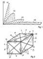
- Curve K1 shows the stress / strain behavior S (D) a high-strength and highly rigid material, one Structural element, such as one with continuous fibers reinforced matrix material, for example a Epoxy resin reinforced with 50% carbon fibers.
- Curve K2 shows a thermoplastic material reinforced with short fibers.
- the curve K3 shows the S (D) behavior of the unreinforced thermoplastic material and the curve K4 that Stress / strain behavior of a so-called structural foam, such as a polycarbonate foam.
- each Structural elements For the production of molded parts with construction structures will start from the manufacture of each Structural elements assumed. For example, of pultrusion or continuous extrusion of pipes, rods, Profiles and the like, which endless materials then divided into the desired length become.
- Thermoplastic continuous fiber reinforced Structural elements are e.g. made by pultrusion.
- continuous fiber reinforcement is used extruded thermoset materials, which either by harden the corresponding additives quickly or which ones Post-treatment, such as post-annealing, UV treatment and the like, be hardened. It is also possible to do this To produce continuous materials by coextrusion by As described above, the structural elements have multiple layers are trained.
- the inner core can, for example, consist of the fiber reinforced thermoset material, while the outermost layer at least partially from one thermoplastic material is made, such as made of polypropylene, polycarbonate and the like. It is of course important that the individual layers of material adhere well to one another or are compatible.
- Good liability can be achieved on the one hand by Adhesion at the interface or through or Diffusion of the molecules in the two halves on both sides of the Boundary layer into each other.
- the latter can, for example can be achieved by using thermosets on the surface yet are not fully cured or meltable Thermoplastics can be arranged on the surface.
- Good adhesion is also achieved by the boundary layer a chemical reaction between the two Boundary-forming polymers or between the Molecules of the polymers. In the end it is possible also, a bonding layer between the two polymers (9 in Fig. 3c) to be arranged.
- the supporting structure After the supporting structure has been manufactured, it is an injection mold or a mold is inserted, whereupon the thermoplastic polymer mass is injected or poured. It is now essential that the injected or poured Polymer mass is compatible with the outermost layer of the respective structural elements of the supporting structure or that the surface of the supporting structure looks good connects with the polymer mass. Now that it's possible the polymer mass for forming the molded part or the Designing the structure of the structure in turn in multiple layers, after the injected or poured polymer mass either the now encased load-bearing structure in another injection mold or Mold can be entered, or the volume of the The present injection mold or casting mold can thereby can be enlarged by sliding elements in the walls are provided. It is about so-called multiple tools, which inject or Allow pouring in of several polymer masses Formation of a multi-layer molded part.
- the lightest possible molded part with a construction structure to obtain it is advantageous to the polymer mass form at least partially foamed.
- Molded parts such as housings, tanks, bodies and the like, are easily recyclable by the Polymer mass can be granulated again by melting can while the fiber reinforced structural elements again used for example as fiber reinforcement can find.
- the idea of the present invention is that first a scaffold or the supporting structure so-called yard goods is manufactured or that individual structural elements of this scaffold on simple and cheap way to manufacture what the Elements assembled using robots, for example become.
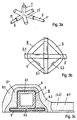
- Fig. 2 shows a liquid tank 11 as an example of a plastic molded part according to the invention with a structural structure, the walls are shown transparently are so that the supporting structure 3 is visible.
- This load-bearing structure 3 consists of a space frame 13 with diagonal bars 17 as well as longitudinal bars 19 and cross bars 21 as structural elements 5, which for consolidation or Bracing the individual walls.
- the individual structural elements or rods with each other connected for example by means of a connector part 25 can be done as a connecting element 7, such as is shown in Fig. 3a.
- longitudinal bars 17, 19 and 21 can be, for example, by means of carbon fibers reinforced polyurethane resin rods act which are surface-coated or surface-treated in order to better adhesion of those surrounding the individual rods Ensure polymer mass.
- These structural elements 3 can also have other profile shapes, e.g. as pipes be trained.
- the spaces 24 and 26 are then also as walls between the bars, for example by means of injection molding, filled.
- connection elements (7) and connection areas 6 of different types rod-like, longitudinally oriented (5.1) and flat (5.2) Structural elements, which in a suitable selection and Compilation form the supporting structure 3.
- Fig. 3a shows a connector part 7 as a connector 25 with which e.g. the bars 17, 19, 21 of Fig. 2 are connected by inserting and gluing.
- Fig. 3b shows in supervision a connection of two itself crossing longitudinal profiles, e.g. in the form of rectangular tubes as structural elements 5, which as a plate flat connecting element 7 are glued and wherein the whole e.g. through a fiber-reinforced polymer mass 8 is surrounded and held together as a partial molded part.
- This molded part here forms a connection area 6.
- 3c illustrates in cross section a connection of a square tube profile as a longitudinally oriented structural element 5.1, which on a plate as a flat Structural element 5.2 is glued or welded on.
- a wall area which e.g. from polymer mass 8 with foamed partial areas 8.0 can exist or which other flat Structural elements 5.2, such as grids or honeycombs, contain can.
- the surrounding form-forming polymer mass 8 forms here also a reinforcing connection area 6 the polymer mass can also consist of two or more layers, 8.1, 8.2.
- tie layer here 9 to establish a very strong connection between Structural elements and polymer mass on the Structural elements 5.1 and 5.2, e.g.
- the walls of a container can also, for example with lath-shaped, i.e. flat structural elements as Struts to be supported, such as the box-shaped container of Fig. 4 is shown.
- lath-shaped, i.e. flat structural elements as Struts to be supported such as the box-shaped container of Fig. 4 is shown.
- the individual structural elements, which form the supporting structure for example can be produced "endlessly" by means of pultrusion or extrusion are made of continuous fiber reinforced thermoplastic or thermoset material.
- stiff and having a very high modulus Structural elements are required can be a special one high proportion of continuous fiber reinforcement e.g. 50-60 Vol% are used.
- novolaks at least in part, which result in a higher crosslink density than that commercially available duromers.
- the continuous fiber reinforcements can be all fibers mentioned at the beginning act, these preferably before incorporation into the matrix polymer must be substructed so that its surface is good It is wettable by the one that includes these fibers Polymer.
- This is already one best known technology, because the strengthening of Thermoplastics and thermosets, for example with glass, Carbon fibers, aramid fibers and the like, in the state is well known in the art.
- FIG. 5 Another example of such a supporting structure 3 is shown in FIG. 5 with curved, longitudinally oriented Profiles or tubes as structural elements 5 and with connecting elements 7, 25, for example for the Formation of a wall of a basin, a pipe wall, a tube with a very large diameter, one Pressure tanks etc.
- FIG. 6 in turn shows a cable car cabin 31, whose load-bearing framework consists of an inventive, supporting structure 3 is formed.
- a cable car cabin 31 whose load-bearing framework consists of an inventive, supporting structure 3 is formed.
- Reinforcing element in the side walls relatively light dimensioned, lattice-like structures 37 as another To use example of flat structural elements 5.2, which in a frame 39 of the supporting structure 3 are attached.
- FIG. 7 shows a vehicle cell 41 as a further example of an automobile, with a high-strength supporting structure shown.
- This consists of strong longitudinal ones Structural elements 5.1 connected to flat parts 5.2, partial areas of the supporting structure with the surrounding Polymer mass can form 8 body parts. In this way is also a self-supporting plastic body produced.
Landscapes
- Engineering & Computer Science (AREA)
- Mechanical Engineering (AREA)
- Chemical & Material Sciences (AREA)
- Composite Materials (AREA)
- Transportation (AREA)
- Combustion & Propulsion (AREA)
- Manufacturing & Machinery (AREA)
- Architecture (AREA)
- Structural Engineering (AREA)
- Laminated Bodies (AREA)
- Moulding By Coating Moulds (AREA)
- Sewage (AREA)
- Body Structure For Vehicles (AREA)
- Injection Moulding Of Plastics Or The Like (AREA)
Abstract
Description
Die vorliegende Erfindung betrifft ein Kunststoff-Formteil mit Konstruktionsstruktur gemäss Oberbegriff von Anspruch 1, wie ein Behälter, ein Gehäuse, ein Gas- oder Flüssigkeitstank, eine Rohrleitung, eine Fahrzeugzelle, eine Kabine, eine Karosserie oder dergleichen, sowie ein Verfahren zur Herstellung eines derartigen Kunststoff-Formteils mit Konstruktionsstruktur für die Herstellung von Autokarosserien, Transportbehältern, Seilbahnkabinen, Brennstofftanks und ähnlichem, d.h. also von Formteilen welche gleichzeitig eine lasttragende Konstruktionsstruktur bilden.The present invention relates to a plastic molded part Construction structure according to the preamble of claim 1, such as a container, a case, a gas or liquid tank, a pipeline, a vehicle cell, a Cabin, a body or the like, and a Process for producing such a molded plastic part with construction structure for manufacturing of car bodies, transport containers, cable car cabins, Fuel tanks and the like, i.e. so of molded parts which is also a load-bearing construction structure form.
Die Herstellung von Gehäusen, Kabinen, Karosserien, grösseren Behältnissen, Brennstofftanks und dergleichen erfolgt in der Regel immer noch meist mit metallischen Werkstoffen, wie beispielsweise Metallblechen, Stahlkonstruktionen etc. Infolge des grossen Gewichtes, der Korrosionsanfälligkeit, den relativ teuren Herstellverfahren und des umständlichen Handlings wird aber mehr und mehr versucht, auf leichtere und einfacher verarbeitbare Werkstoffe, wie Kunststoffe bzw. generell Polymere, bzw. auf Kunststoffkonstruktionen, auszuweichen.The manufacture of housings, cabins, bodies, larger containers, fuel tanks and the like is usually still done with metallic Materials such as sheet metal, steel structures etc. Due to the great weight that Susceptibility to corrosion, the relatively expensive manufacturing process and the cumbersome handling becomes more and tried more on lighter and easier to process Materials such as plastics or generally polymers, or on plastic constructions.
So werden beispielsweise für Behälter, Kunststofftanks für Brennstoffe, Rohrleitungen, Fahrzeugzellen etc. sogenannte Wickelverfahren verwendet, wo beispielsweise mit flüssigem Harz getränkte, sogenannte Rovings, Fäden aus Glas oder Kunststofffasern, Gewebebänder usw. um einen Kern in eine Form gewickelt und dort ausgehärtet werden. Einerseits ist die Formgebung nur sehr beschränkt möglich, und anderseits sind die so hergestellten Formkörper kaum nachbearbeitbar. Auch weisen sie keine glatte Oberfläche auf, und um eine ausreichende Festigkeit zu erzielen, müssen relativ grosse Wandstärken gewählt werden.For example, for containers, plastic tanks for So-called fuels, pipelines, vehicle cells etc. Winding process used where, for example, with liquid Resin-soaked, so-called rovings, threads made of glass or Plastic fibers, fabric tapes, etc. around a core in one Form wrapped and cured there. On the one hand is the design is only possible to a very limited extent, and on the other hand the moldings produced in this way are hardly reworkable. Nor do they have a smooth surface, and around one To achieve sufficient strength must be relatively large Wall thicknesses can be selected.
Gemäss einem weiteren bekannten Verfahren werden in grosse Spritzgussformen Endlosverstärkungsfasern, textile Fasergebilde wie Fasermatten, Platten und Faserhalbzeug und dergleichen lose eingelegt, womit jedoch nur eine sehr beschränkte tragende Funktion erreichbar ist. Oder aber es erfolgt eine Ganzkörper-Faserverstärkung durch Einarbeiten von Kurzfasern in den zu verarbeitenden thermoplastischen Kunststoff. Entweder sind diese Herstellverfahren sehr kompliziert und aufwendig, oder aber die lediglich kurzfaserverstärkten Kunststoffe ergeben bei weitem nicht die erforderliche Festigkeit der herzustellenden Konstruktionsstruktur.According to another known method, large Injection molds, continuous reinforcement fibers, textile fiber structures such as fiber mats, sheets and semi-finished fiber and The like inserted loosely, but only a very limited supporting function is achievable. Or it whole-body fiber reinforcement takes place by incorporation of short fibers in the thermoplastic to be processed Plastic. Either these manufacturing processes are very complicated and expensive, or the only short fiber reinforced Plastics are far from giving that required strength of the construction structure to be produced.
Wieder gemäss einer weiteren Variante werden mittels faserverstärkten Duromeren hergestellte Matten oder Platten mittels Tiefziehverfahren in die erforderliche Form gebracht, worauf die endgültige Aushärtung beispielsweise in einer Pressform oder durch Nachtempern erfolgt. Dies erlaubt jedoch nur eine sehr eingeschränkte Formgebung und nur beschränkte Tragfunktionen. Auch weisen diese Teile keinen akzeptablen Oberflächenfinish auf, und zudem ist in der Regel die Reaktionszeit beim Aushärten zu lange.According to a further variant, again mats or sheets made of fiber-reinforced thermosets into the required shape using a deep-drawing process brought, whereupon the final curing, for example in a press mold or by post-annealing. This however, allows only a very limited shape and only limited load functions. These parts also show does not have an acceptable surface finish and is also in usually the reaction time when curing too long.
Aus der EP 0 687 546 ist ein Hohlkörper mit innenliegendem Stützrahmen bekannt, welcher jedoch keine lasttragende Funktion aufweist. Dieser Hohlkörper ist ein dünnwandiges Gehäuse, das in Blasformtechnik aus einem thermoplastischen Kunststoffschlauch hergestellt ist und das einen Stützrahmen aus Kunststoff-Spritzguss enthält. Der Stützrahmen ist an Anlagepunkten mit dem Gehäuse verbunden. Damit wird z.B. ein Filtergehäuse als Aktivkohlefilter oder ein Resonatorraum zur Dämpfung von Ansauggeräuschen gebildet. Der Stützrahmen dient nur der Formstabilität, er kann jedoch keine lasttragende Funktion erfüllen und weist auch keine Faserverstärkung auf.A hollow body is known from EP 0 687 546 internal support frame known, but none has load-bearing function. This hollow body is a thin-walled housing that is made from a blow molding technique thermoplastic hose is made and which contains a support frame made of plastic injection molding. The support frame is at contact points with the housing connected. This is e.g. a filter housing as Activated carbon filter or a resonator room to dampen Intake noise formed. The support frame serves only the Dimensional stability, but it cannot perform a load-bearing function meet and has no fiber reinforcement.
Aus der DE 2636 557 ist eine Luftfracht-Containerhaube aus duromeren glasfaserverstärktem Kunststoff Gfk (Glasfaser-Polyester) bekannt, die mit einem eingelegten Portalrahmen versteift ist und welcher eine durchgehende Endlosfaser-Verstärkung an der Frontöffnung enthält, um eine formstabile Frontöffnung zu bilden. Auch diese Containerhaube weist keine lasttragende Struktur auf.An air freight container hood is known from DE 2636 557 thermoset glass fiber reinforced plastic Gfk (glass fiber polyester) known with an inserted portal frame is stiffened and which is a continuous continuous fiber reinforcement at the front opening contains one form stable front opening. This too Container hood has no load-bearing structure.
Die US 4652171 offenbart keine Kunststoff-Formteile sondern eine ganz andere, gegensätzliche Produktart, nämlich reine hochfeste Tragstrukturen mit minimalem Gewicht. Hier werden einzelne stabartige, hochfeste faserverstärkte Kunststoffelemente miteinander verbunden, so dass sehr leichte fachwerkartige Tragstrukturen für Flugzeuge erstellt werden können. Dabei werden Stäbe und Rohre in einem komplizierten, sehr aufwendigen und zeitraubenden Verfahren mittels unidirektionalen Fasern, geflochtenen Strümpfen und duromerem Harz miteinander verbunden. Dieses duromere Verbindungsverfahren ist jedoch nicht nur sehr teuer, sondern auch so zeitaufwendig, dass kurze Taktzeiten unmöglich sind.US 4652171 does not disclose molded plastic parts but a completely different, opposite product type, namely pure high-strength supporting structures with minimal weight. Be here single rod-like, high-strength fiber-reinforced Plastic elements joined together, so very lightweight truss-like support structures for aircraft can be created. Rods and tubes are in a complicated, very complex and time-consuming Method using unidirectional fibers, braided Stockings and thermosetting resin bonded together. This However, duromeric joining process is not only very expensive, but also so time consuming that short cycle times are impossible.
Es ist daher eine Aufgabe der vorliegenden Erfindung, die Nachteile der bekannten Methoden zu überwinden und ein Kunststoff-Formteil mit Konstruktionsstruktur zu schaffen sowie ein Verfahren zu dessen Herstellung anzugeben, welche auf einfache und kostengünstige Art und Weise und mit kurzen Taktzeiten, unter Verwendung von möglichst leichten Polymerwerkstoffen herstellbar ist und mit welchen ein weiter Bereich von Formgebungen und lasttragenden Funktionen erfüllbar ist. It is therefore an object of the present invention that To overcome disadvantages of the known methods and one To create plastic molding with construction structure and to specify a process for its production, which in a simple and inexpensive way and with short cycle times, using the lightest possible Polymer materials can be produced and with which one wide range of shapes and load-bearing Functions is achievable.
Erfindungsgemäss wird die gestellte Aufgabe mittels eines Kunststoff-Formteils mit Konstruktionsstruktur nach Anspruch 1 und einem Verfahren nach Anspruch 16 gelöst.According to the invention, the object is achieved by means of a Plastic molded part with construction structure after Claim 1 and a method according to claim 16 solved.
Das Kunststoff-Formteil mit Konstruktionsstruktur wird gebildet aus einfachen einzelnen hochfesten faserverstärkten Strukturelementen, welche zu einer tragenden Struktur zusammengesetzt und miteinander verbunden sind und welche eine mindestens in Teilen dieser tragenden Struktur von einer das Formteil bildenden Polymermasse umgossen ist. Damit werden auf einfache Art aus relativ kostengünstiger Meterware Strukturelemente und Konstruktionsstrukturen in beliebiger Form erzeugt und wobei die gewünschte Formgebung und Oberfläche auf einfache Art durch Giessen oder Spritzen der Polymermasse erzeugt wird. Zudem sind damit kurze Taktzeiten erreichbar. Im Prinzip können damit weitgehende beliebige Flächenformen und lasttragende Funktionen der integrierten tragenden Struktur erzeugt werden. Vollständiges Umgiessen bzw. Umspritzen der tragenden Struktur mit der Polymermasse ergibt eine vollständig geschützte, glatte Oberfläche. Beispielsweise für grosse Raumgitter-Strukturen können aber auch nur Teilbereiche, vor allem an Verbindungsstellen der Strukturelemente, von der Polymermasse umgossen sein.The plastic molding with construction structure is formed from simple single high-strength fiber-reinforced Structural elements that lead to a load-bearing Structure composed and connected with each other and which one at least in parts of it is load-bearing Structure of a polymer mass forming the molded part is encapsulated. This turns relative in a simple way inexpensive yard goods structural elements and construction structures generated in any form and the desired shape and surface in a simple way is produced by pouring or spraying the polymer mass. In addition, short cycle times can be achieved. Basically can thus largely any surface shapes and load-bearing functions of the integrated load-bearing Structure can be created. Complete casting or Injection molding of the supporting structure with the polymer mass results in a completely protected, smooth surface. For example, for large space lattice structures but also only partial areas, especially at connection points the structural elements, the polymer mass be cast around.
Die abhängigen Patentansprüche betreffen vorteilhafte Weiterbildungen der Erfindung bezüglich Materialien, Materialkombinationen, Verbindungen und Aufbau von tragenden Strukturen und Formteilen mit besonders günstigen Eigenschaften.The dependent claims relate to advantageous ones Further developments of the invention with regard to materials, Material combinations, connections and structure of load-bearing structures and molded parts with special favorable properties.
Als Verstärkungsfasern für diese, die tragende Struktur bildenden Strukturelemente eignen sich insbesondere Endlosfaserverstärkungen aus Glasfasern, Kohlenstoff-, Polypropylen-, Polyethylen-, Aramid- oder anderen hochfesten Polymerfasern. Als Matrix für die Verstärkungsfasern eignen sich vorzugsweise Thermoplaste wie Polyamid (PA), Polypropylen (PP), Polyethylentherephthalat (PET), Polybutylentherephthalat (PBT), Polycarbonat (PC), Polyimid (PI), Polyacrylate, Polyphenylensulfid (PPS), Polyetheretherketon (PEEK).As reinforcing fibers for this, the supporting structure Structural elements are particularly suitable Continuous fiber reinforcements made of glass fibers, carbon, Polypropylene, polyethylene, aramid or others high-strength polymer fibers. As a matrix for the reinforcing fibers thermoplastics such as polyamide are particularly suitable (PA), polypropylene (PP), polyethylene terephthalate (PET), Polybutylene terephthalate (PBT), polycarbonate (PC), Polyimide (PI), polyacrylates, polyphenylene sulfide (PPS), Polyetheretherketone (PEEK).
Daneben eignen sich aber mindestens teilweise auch Duromermaterialien, wie beispielsweise Polyurethan (PUR), ungesättigte Polyesterharze, Epoxidharze, Phenolharze, Aminoplaste oder aber gegebenenfalls Novolackharze.In addition, they are also at least partially suitable Thermoset materials, such as polyurethane (PUR), unsaturated polyester resins, epoxy resins, phenolic resins, Aminoplasts or, if necessary, novolac resins.
Bei diesen, die tragende Struktur bildenden Strukturelementen kann es sich beispielsweise um längsorientierte Gebilde wie Stangen, Rohre, Längsprofile, wie T-Profile, L-winkel und um flächige Gebilde wie Platten, Matten, Waben, Gitter und dergleichen handeln. Diese Strukturelemente können generell mittels in der Kunststofftechnik üblichen Herstellmethoden produziert werden, vorzugsweise mittels Pultrusion, Extrusion, Stranggiessen, Strangpressen oder Kalandrieren. Bevorzugt werden diese Strukturelemente durch Zuschneiden, Nachbearbeiten und Konfektionieren von "endlos"-Material hergestellt.In these structural elements that form the supporting structure can be, for example, length-oriented Structures such as rods, tubes, longitudinal profiles such as T-profiles, L-angles and around flat structures such as plates, mats, Act honeycombs, grids and the like. These structural elements can generally be used in plastics technology usual production methods are produced, preferably by means of pultrusion, extrusion, continuous casting, extrusion or calendering. These are preferred Structural elements by cutting, reworking and Made up of "endless" material.
Zur Herstellung der tragenden Struktur werden die einzelnen Strukturelemente durch Stecken, Schrauben, Kleben, Schweissen und dergleichen miteinander verbunden, wobei jeweils im Verbindungsbereich entsprechende Kupplungs- oder Verbindungselemente angeordnet werden können.To create the load-bearing structure, the individual structural elements by plugging, screwing, Gluing, welding and the like connected together, where corresponding in the connection area Coupling or connecting elements are arranged can.
Die einzelnen Strukturelemente können mehrschichtig aufgebaut werden, mit mindestens einem hochfesten Kern und einer äussersten Schicht, welche vorzugsweise kompatibel ist mit der das Element unmittelbar umgebenden Polymermasse bzw. welche äusserste Schicht auf der das Element unmittelbar umgebenden Polymermasse gut haftet bzw. sich mit dieser gut verbinden oder vermischen lässt. Gute Haftung zwischen Strukturelementen und thermoplastischer Polymermasse wird erreicht durch kompatible Polymermaterialien, welche ineinander diffundieren und sich dadurch mikroskopisch verbinden, oder durch chemische Bindungen.The individual structural elements can have multiple layers be built with at least one high strength core and an outermost layer, which is preferably compatible is with the polymer mass immediately surrounding the element or which outermost layer on which the element polymer mass immediately surrounding or adheres well can be easily connected or mixed with this. Quality Adhesion between structural elements and thermoplastic Polymer mass is achieved through compatible polymer materials, which diffuse into each other and themselves thereby connecting microscopically, or by chemical Bonds.
Gemäss einer bevorzugten Ausführungsvariante ist die äusserste Schicht der einzelnen Strukturelemente bzw. deren Oberfläche wenigstens nahezu identisch mit der unmittelbar das Element umgebenden Polymermasse. Dabei sind auch Polymerblends einsetzbar.According to a preferred embodiment variant, the outermost layer of the individual structural elements or whose surface is at least almost identical to that polymer mass directly surrounding the element. there polymer blends can also be used.
Die das Formteil oder die Konstruktionsstruktur bildende Polymermasse umfasst mindestens teilweise ein thermoplastisches Polymer, wie Polyamid (PA), Polypropylen (PP), Polyethylentherephthalat (PET), Polybutylentherephthalat (PBT), Polycarbonat (PC), Polyimid (PI), Polyacrylate, Polyphenylensulfid (PPS), Polyetheretherketon (PEEK). Im Prinzip werden möglichst gleiche Polymere wie für die thermoplastische Matrix oder die Beschichtung der Strukturelemente eingesetzt. Dabei kann die Polymermasse mehrschichtig ausgebildet sein mit vom Element zur Oberfläche des Formteils oder der Konstruktionsstruktur hin abnehmender Steifigkeit und Festigkeit. Dabei ist es auch möglich, dass die Polymermasse wenigstens bereichsweise geschäumt oder eingefärbt ist.The one that forms the molded part or the structural structure Polymer mass at least partially comprises a thermoplastic Polymer, such as polyamide (PA), polypropylene (PP), Polyethylene terephthalate (PET), polybutylene terephthalate (PBT), polycarbonate (PC), polyimide (PI), polyacrylates, Polyphenylene sulfide (PPS), polyether ether ketone (PEEK). in the In principle, the same polymers are used as for the thermoplastic matrix or the coating of the Structural elements used. The polymer mass be multi-layered with from the element Surface of the molded part or the structural structure decreasing stiffness and strength. It is also possible that the polymer mass at least in some areas is foamed or colored.
Die abnehmende Steifigkeit und Festigkeit vom Strukturelement zur äusseren Oberfläche der Polymermasse ist dann wichtig, um bei auftretenden Beschädigungen bzw. auftretender Deformation von Formteil mit Konstruktionsstruktur eine möglichst hohe Energieaufnahme zu garantieren. Insbesondere bei der Herstellung von Fahrzeugzellen, Automobilkarosserien, Kabinen und dergleichen, ist es wichtig, dass die, die Karosserie bildenden Formteile mit Konstruktionsstruktur bei sogenannten "crash"-Tests eine möglichst grosse Energieaufnahme ergibt, um beispielsweise einer in einem Automobil oder einer Kabine befindlichen Person grösstmöglichen Schutz bieten zu können.The decreasing stiffness and strength of the structural element then to the outer surface of the polymer mass important in the event of damage or occurring deformation of molded part with construction structure the highest possible energy consumption to guarantee. Especially in the manufacture of Vehicle cells, automobile bodies, cabins and the like, it is important that the body forming moldings with construction structure So-called "crash" tests the greatest possible energy consumption results in, for example, one in an automobile or a person in the cabin as much as possible To be able to offer protection.
Die Erfindung wird nun anschliessend anhand von Ausführungsbeispielen unter Bezug auf die beigefügten Figuren näher erläutert.The invention will now be described using exemplary embodiments with reference to the accompanying figures explained in more detail.
Dabei zeigen:
- Fig. 1
- Spannungs/Dehnungsdiagramme von verschiedenen eingesetzten Materialien;
- Fig. 2, 2a
- einen Flüssigkeitstank als Beispiel eines erfindungsgemässen Kunststoff-Formteils mit Konstruktionsstruktur;
- Fig. 3a-c
- Beispiele von Verbindungen, Verbindungselementen und -bereichen der tragenden Struktur;
- Fig. 4
- einen Behälter mit kistenförmiger tragender Struktur;
- Fig. 5
- eine zylinderförmige tragende Struktur, z.B. als Rundbecken;
- Fig. 6
- eine Seilbahnkabine;
- Fig. 7
- eine Fahrzeugzelle mit Karosserieteilbereichen.
- Fig. 1
- Stress / strain diagrams of various materials used;
- Fig. 2, 2a
- a liquid tank as an example of a molded plastic part according to the invention with a structural structure;
- 3a-c
- Examples of connections, connecting elements and areas of the supporting structure;
- Fig. 4
- a container with a box-shaped supporting structure;
- Fig. 5
- a cylindrical supporting structure, eg as a round pool;
- Fig. 6
- a cable car cabin;
- Fig. 7
- a vehicle cell with body parts.
In Fig. 1 ist ein Spannungs/Dehnungsdiagramm dargestellt, anhand welchem obiger Sachverhalt dargelegt werden soll. 1 shows a stress / strain diagram, on the basis of which the above facts should be explained.
Die Kurve K1 zeigt das Spannungs/Dehnungsverhalten S(D) eines hochfesten und hochsteifen Materials, eines Strukturelements, wie beispielsweise eines mit Endlosfasern verstärkten Matrix-Materials, beispielsweise ein mit 50% Kohlenstofffasern verstärktes Epoxidharz. Kurve K2 zeigt ein mittels Kurzfasern verstärktes Thermoplastmaterial. Die Kurve K3 zeigt das S(D)Verhalten des unverstärkten Thermoplastmaterials und die Kurve K4 das Spannungs/Dehnungsverhalten eines sogenannten Strukturschaumes, wie beispielsweise eines Polycarbonatschaumes.Curve K1 shows the stress / strain behavior S (D) a high-strength and highly rigid material, one Structural element, such as one with continuous fibers reinforced matrix material, for example a Epoxy resin reinforced with 50% carbon fibers. Curve K2 shows a thermoplastic material reinforced with short fibers. The curve K3 shows the S (D) behavior of the unreinforced thermoplastic material and the curve K4 that Stress / strain behavior of a so-called structural foam, such as a polycarbonate foam.
Die Energieaufnahme der einzelnen Materialien bis zum Bruch wird durch die unter der Kurve liegende, schraffiert dargestellte Fläche repräsentiert. Es ist also wichtig, dass die Fläche unter den einzelnen Kurven möglichst gross ist, was sich dann ergibt, wenn ein möglichst abgestuftes Spannungs/Dehnungsverhältnis vom Kern der einzelnen Strukturelemente (z.B. Kurve K1) bis zur äusseren Oberfläche des Formteils (z.B. Kurve K3, K4) gewählt wird. Mit anderen Worten ist es vorteilhaft, wenn die Steifigkeit der gewählten Materialien vom Kern der einzelnen Strukturelemente gegen die Oberfläche des Formteils hin abnimmt. Allerdings ist es natürlich auch wichtig, dass die einzelnen gewählten Materialien miteinander kompatibel sind, damit an den Grenzflächen bei der Energieaufnahme keine Ablösung stattfindet bzw. kein Bruch auftritt.The energy consumption of the individual materials up to Fracture is hatched by the one below the curve represented area represented. So it's important that the area under the individual curves is as large as possible is what arises when a graded as possible Stress / strain ratio from the core of each Structural elements (e.g. curve K1) up to the outer surface of the molded part (e.g. curve K3, K4) is selected. With in other words, it is advantageous if the rigidity of the selected materials from the core of the individual structural elements decreases towards the surface of the molded part. However, it is of course also important that the individually selected materials compatible with each other are so at the interfaces when it comes to energy consumption no detachment takes place or no breakage occurs.
Für die Herstellung der Formteile mit Konstruktionsstrukturen wird zunächst von der Herstellung der einzelnen Strukturelemente ausgegangen. Dabei wird beispielsweise von Pultrusion oder Endlosextrusion von Rohren, Stäben, Profilen und dergleichen ausgegangen, welche Endlosmaterialien anschliessend in die gewünschte Länge unterteilt werden. Thermoplastische endlosfaserverstärkte Strukturelemente werden z.B. durch Pultrusion hergestellt. Bei Extrusion werden beispielsweise endlosfaserverstärkte duromere Materialien extrudiert, welche entweder durch entsprechende Zusätze rasch aushärten oder welche durch Nachbehandeln, wie Nachtempern, UV-Behandlung und dergleichen, gehärtet werden. Es ist auch möglich, diese Endlosmaterialien durch Koextrusion herzustellen, indem, wie vorab beschrieben, die Strukturelemente mehrschichtig ausgebildet sind. Der innere Kern kann beispielsweise aus dem faserverstärkten duromeren Material bestehen, währenddem die äusserste Schicht mindestens teilweise aus einem thermoplastischen Material gefertigt ist, wie beispielsweise aus Polypropylen, Polycarbonat und dergleichen. Wichtig ist natürlich, dass die einzelnen Materialschichten untereinander gut haften bzw. kompatibel sind.For the production of molded parts with construction structures will start from the manufacture of each Structural elements assumed. For example, of pultrusion or continuous extrusion of pipes, rods, Profiles and the like, which endless materials then divided into the desired length become. Thermoplastic continuous fiber reinforced Structural elements are e.g. made by pultrusion. In the case of extrusion, for example, continuous fiber reinforcement is used extruded thermoset materials, which either by harden the corresponding additives quickly or which ones Post-treatment, such as post-annealing, UV treatment and the like, be hardened. It is also possible to do this To produce continuous materials by coextrusion by As described above, the structural elements have multiple layers are trained. The inner core can, for example, consist of the fiber reinforced thermoset material, while the outermost layer at least partially from one thermoplastic material is made, such as made of polypropylene, polycarbonate and the like. It is of course important that the individual layers of material adhere well to one another or are compatible.
Gute Haftung kann einerseits erreicht werden durch Adhäsion an der Grenzschicht bzw. Grenzfläche oder durch Diffusion der Moleküle in den beiden Hälften beidseits der Grenzschicht ineinander. Letzteres kann beispielsweise erreicht werden, indem Duromere an der Oberfläche noch nicht vollständig ausgehärtet sind oder indem anschmelzbare Thermoplaste an der Oberfläche angeordnet werden. Gute Haftung wird aber auch erzielt, indem an der Grenzschicht eine chemische Reaktion zwischen den beiden die Grenzschicht bildenden Polymeren erfolgt bzw. zwischen den Molekülen der Polymere. Schlussendlich möglich ist es auch, zwischen den beiden Polymeren eine haftvermittelnde-Verbindungsschicht (9 in Fig. 3c) anzuordnen.Good liability can be achieved on the one hand by Adhesion at the interface or through or Diffusion of the molecules in the two halves on both sides of the Boundary layer into each other. The latter can, for example can be achieved by using thermosets on the surface yet are not fully cured or meltable Thermoplastics can be arranged on the surface. Good adhesion is also achieved by the boundary layer a chemical reaction between the two Boundary-forming polymers or between the Molecules of the polymers. In the end it is possible also, a bonding layer between the two polymers (9 in Fig. 3c) to be arranged.
Nach Herstellen der einzelnen Strukturelemente, wie beispielsweise Stäbe, Platten, Rohre, T-Profile usw., werden diese Elemente zur tragenden Struktur zusammengesetzt. Dies kann beispielsweise durch Zusammenstecken mittels verbindungselementen geschehen, welche Verbindungselemente Steckpartien, Schraubpartien, Einrastpartien und dergleichen aufweisen können. Diese Verbindungselemente können entweder starr sein oder aber auch gelenkig ausgebildet sein, so dass die erzeugte tragende Struktur entweder steif ist oder aber über eine gewisse Gelenkigkeit verfügen kann. Das Zusammenfügen ist aber auch direkt möglich, indem die einzelnen Strukturelemente miteinander verklebt, verschweisst, verschraubt usw. werden. Wichtig ist in jedem Fall, dass mindestens ein Teil der Strukturelemente der tragenden Struktur miteinander verbunden ist.After manufacturing the individual structural elements, such as for example bars, plates, pipes, T-profiles etc., these elements are put together to form the supporting structure. This can be done, for example, by plugging them together what connecting elements are done by means of connecting elements Plug-in parts, screw parts, snap-in parts and the like. These fasteners can either be rigid or else be articulated so that the generated load-bearing Structure is either stiff or over a certain Flexibility. But putting it together is also possible directly by the individual structural elements glued, welded, screwed together etc. become. It is important in any case that at least one Part of the structural elements of the supporting structure is interconnected.
Nach dem Herstellen der tragenden Struktur wird diese in eine Spritzgussform bzw. eine Giessform eingelegt, worauf die thermoplastische Polymermasse eingespritzt bzw. eingegossen wird. Dabei ist es nun wesentlich, dass die einzuspritzende bzw. einzugiessende Polymermasse kompatibel ist mit der äussersten Schicht der jeweiligen Strukturelemente der tragenden Struktur bzw. dass die Oberfläche der tragenden Struktur sich gut mit der Polymermasse verbindet. Da es nun möglich ist, die Polymermasse für das Bilden des Formteils bzw. der Konstruktionsstruktur wiederum mehrschichtig auszubilden, kann nach erfolgtem Aushärten der eingespritzten bzw. eingegossenen Polymermasse entweder die nun ummantelte tragende Struktur in eine weitere Spritzgussform bzw. Giessform eingegeben werden, oder aber das Volumen der vorliegenden Spritzgussform bzw. Giessform kann dadurch vergrössert werden, indem in den Wandungen Schieberelemente vorgesehen sind. Es handelt sich dabei um sogenannte Mehrfach-Werkzeuge, welche das Einspritzen bzw. Eingiessen von mehreren Polymermassen zulassen zur Bildung eines mehrschichtigen Formteils.After the supporting structure has been manufactured, it is an injection mold or a mold is inserted, whereupon the thermoplastic polymer mass is injected or poured. It is now essential that the injected or poured Polymer mass is compatible with the outermost layer of the respective structural elements of the supporting structure or that the surface of the supporting structure looks good connects with the polymer mass. Now that it's possible the polymer mass for forming the molded part or the Designing the structure of the structure in turn in multiple layers, after the injected or poured polymer mass either the now encased load-bearing structure in another injection mold or Mold can be entered, or the volume of the The present injection mold or casting mold can thereby can be enlarged by sliding elements in the walls are provided. It is about so-called multiple tools, which inject or Allow pouring in of several polymer masses Formation of a multi-layer molded part.
Auf diese Art und Weise wird es auch möglich, die oben beschriebene Veränderung der Steifigkeit von innen nach aussen zu bewerkstelligen, indem beispielsweise gegen aussen hin Polymermaterialien, wie beispielsweise Polyethylen-Polypropylen Copolymere, Polyester wie PBT oder Topas ((polymerisierte zyklische Vinylmonomere) eingespritzt werden können, welche eine relativ niedrige Steifigkeit aufweisen und zudem einen sehr guten Oberflächenfinish ergeben, damit das schliesslich hergestellte Formteil bzw. die Konstruktionsstruktur nicht nachgearbeitet werden muss. Dadurch wird es auch möglich, die äusserste Schicht einzufärben, damit die Notwendigkeit der Lackierung des schlussendlich hergestellten Formteils bzw. der Konstruktionsstruktur entfällt.This way it will also be possible to do the above described change in stiffness from the inside to the inside to accomplish outside, for example against outside polymer materials, such as Polyethylene-polypropylene copolymers, polyesters such as PBT or topaz ((polymerized cyclic vinyl monomers) can be injected, which is a relatively low Have rigidity and also a very good one Surface finish result, so that finally manufactured molded part or the construction structure is not must be reworked. This also makes it possible to paint the outermost layer, hence the need the painting of the molded part ultimately produced or the construction structure is omitted.
Um ein möglichst leichtes Formteil mit Konstruktionsstruktur zu erhalten, ist es vorteilhaft, die Polymermasse wenigstens teilweise geschäumt auszubilden. Geeignet sind beispielsweise sogenannte Strukturschäume beispielsweise aus Polycarbonat, Poyurethan oder Polyester wie PBT oder Topas, welche hervorragende Gewichts-, Festigkeits- und Härteverhältnisse aufweisen, d.h. welche bei geringem Gewicht eine relativ hohe Oberflächenfestigkeit aufweisen.The lightest possible molded part with a construction structure to obtain it is advantageous to the polymer mass form at least partially foamed. Are suitable for example so-called structural foams made of polycarbonate, polyurethane or polyester such as PBT or Topaz, which have excellent weight, strength and Have hardness ratios, i.e. which at low Weight have a relatively high surface strength.
Der grosse Vorteil bei der Verwendung von polymeren Materialien gemäss der vorliegenden Erfindung liegt darin, dass, wie bereits oben erwähnt, die Oberfläche des hergestellten Formteils mit Konstruktionsstruktur nicht nachbearbeitet werden muss. Auch können spezielle Oberflächeneffekte erzielt werden, wie beispielsweise das Polymer einzufärben, womit die Lackierung entfällt. Auch kann der sogenannte "Acryllack-touch" imitiert werden, oder aber es können Oberflächenstrukturen beim Spritzgiessen bzw. Eingiessen eingeformt werden.The big advantage when using polymers Materials according to the present invention is that, as mentioned above, the surface of the manufactured molded part with construction structure not must be reworked. Also special surface effects be achieved, such as that Color the polymer, which eliminates the need for painting. Also the so-called "acrylic paint touch" can be imitated, or it can be surface structures during injection molding or pouring.
Aber auch später ergeben sich weitere grosse Vorteile, indem derart hergestellte Formteile, wie beispielsweise Karosserien, nicht rosten bzw. korrodieren können. Auftretende Kratzer sind kaum sichtbar und führen nicht zum Rosten der Karosserie. Kratzer können auch nachgeschliffen werden, wodurch sie nicht mehr sichtbar sind.But later there are other big advantages, by molding parts produced in this way, for example Bodies, not rust or corrode. Scratches that appear are barely visible and do not lead for rusting the body. Scratches can also be reground through which they are no longer visible.
Ein weiterer Vorteil liegt darin, dass derartige Formteile, wie beispielsweise Gehäuse, Tanks, Karosserien und dergleichen, leicht rezyklierbar sind, indem die Polymermasse mittels Schmelzen wieder granuliert werden kann, währenddem die faserverstärkten Strukturelemente erneut beispielsweise als Faserverstärkung Verwendung finden können.Another advantage is that such Molded parts such as housings, tanks, bodies and the like, are easily recyclable by the Polymer mass can be granulated again by melting can while the fiber reinforced structural elements again used for example as fiber reinforcement can find.
Die Idee der vorliegenden Erfindung liegt darin, dass zunächst ein Gerüst bzw. die tragende Struktur aus sogenannter Meterware hergestellt wird bzw. dass die einzelnen Strukturelemente dieses Gerüstes auf einfache und billige Art und Weise herstellbar sind, worauf die Elemente beispielsweise mittels Robotern zusammengebaut werden.The idea of the present invention is that first a scaffold or the supporting structure so-called yard goods is manufactured or that individual structural elements of this scaffold on simple and cheap way to manufacture what the Elements assembled using robots, for example become.
Im Gegensatz zur bekannten üblichen Ganzkörper-Faserverstärkung mit eingelegten Matten oder den eingangs erwähnten Wickelverfahren werden erfindungsgemäss die Strukturelemente auf einfachste Art und Weise zur tragenden Struktur als Gerüst zusammengebaut, welches Gerüst aber eine wesentlich höhere Festigkeit und Formbeständigkeit des schlussendlichen Formteils garantiert. Selbstverständlich ist es auch gemäss der vorliegenden Erfindung moglich, flächige Strukturelemente wie Matten- oder Wabenstrukturen zu verwenden, wesentlich aber ist, dass diese Matten- oder Wabenstrukturen untereinander und mit weiteren Strukturelementen verbunden werden.In contrast to the well-known conventional whole-body fiber reinforcement with inserted mats or the entrance mentioned winding process according to the invention Structural elements in the simplest way supporting structure assembled as a scaffold, which Scaffolding but a much higher strength and Dimensional stability of the final molded part is guaranteed. Of course it is also according to the Present invention possible, flat structural elements how to use mat or honeycomb structures, essential but is that these mat or honeycomb structures with each other and connected with other structural elements become.
Fig. 2 zeigt einen Flüssigkeitstank 11 als Beispiel eines
erfindungsgemässen Kunststoff-Formteils mit Konstruktionsstruktur,
wobei die Wandungen transparent dargestellt
sind, damit die tragende Struktur 3 sichtbar wird. Diese
tragende Struktur 3 besteht aus einem Raumgitterrahmen 13
mit Diagonalstäben 17 sowie Langsstäben 19 und Querstäben
21 als Strukturelemente 5, welche zur Verfestigung bzw.
Verstrebung der einzelnen Wandungen dienen. In den
jeweiligen Ecken 23 des Flüssigkeitstankes 11 sind die
einzelnen Strukturelemente bzw. Stäbe miteinander
verbunden, was beispielsweise mittels eines Steckverbindungsteils
25 als Verbindungselement 7 erfolgen kann, wie
in Fig. 3a dargestellt ist. Bei den Längsstäben 17, 19 und
21 kann es sich beispielsweise um mittels Kohlenstofffasern
verstärkte Polyurethanharzstäbe handeln, welche
oberflächenbeschichtet bzw. oberflächenbehandelt sind, um
eine bessere Haftung der die einzelnen Stäbe umgebenden
Polymermasse sicherzustellen. Diese Strukturelemente 3
können auch andere Profilformen aufweisen, z.B. als Rohre
ausgebildet sein. Mittels der erwähnten Polymermasse 8
werden dann auch die Zwischenräume 24 und 26 als Wandungen
zwischen den Stäben, beispielsweise mittels Spritzgiessens,
ausgefüllt.Fig. 2 shows a
Die Fig. 3a - 3c illustrieren Verbindungen, Verbindungselemente
(7) und Verbindungsbereiche 6 von verschiedenartigen
stabartigen, längsorientierten (5.1) und flächigen
(5.2) Strukturelementen, welche in geeigneter Auswahl und
Zusammenstellung die tragende Struktur 3 bilden.3a-3c illustrate connections, connection elements
(7) and
Fig. 3a zeigt als Verbindungselement 7 ein Steckverbindungsteil
25 mit welchem z.B. die Stäbe 17, 19, 21 von
Fig. 2 durch Einstecken und Einkleben verbunden werden.Fig. 3a shows a
Fig. 3b zeigt in Aufsicht eine Verbindung von zwei sich
kreuzenden Längsprofilen, z.B. in Form von Rechteckrohren
als Strukturelemente 5, welche auf eine Platte als
flächiges Verbindungselement 7 aufgeklebt sind und wobei
das Ganze z.B. durch eine faserverstärkte Polymermasse 8
als Teilbereichsformteil umgeben und zusammengehalten ist.
Dieses Formteil bildet hier einen Verbindungsbereich 6.Fig. 3b shows in supervision a connection of two itself
crossing longitudinal profiles, e.g. in the form of rectangular tubes
as
Fig. 3c illustriert im Querschnitt eine Verbindung eines
quadratischen Rohrprofils als längsorientiertes Strukturelement
5.1, welches auf eine Platte als flächiges
Strukturelement 5.2 aufgeklebt oder aufgeschweisst ist.
Daneben schliesst sich ein Wandbereich an, welcher z.B.
aus Polymermasse 8 mit geschäumten Teilbereichen 8.0
bestehen kann oder welcher auch weitere flächige
Strukturelemente 5.2, wie Gitter oder Waben, enthalten
kann. Die umgebende formbildende Polymermasse 8 bildet
auch hier einen verstärkenden Verbindungsbereich 6. Dabei
kann die Polymermasse auch aus zwei oder mehr Schichten,
8.1, 8.2, bestehen. Zudem ist hier eine Verbindungsschicht
9 zur Vermittlung einer sehr starken Verbindung zwischen
Strukturelementen und Polymermasse auf den
Strukturelementen 5.1 und 5.2, z.B. deren äusserste
Schicht bildend, vorgesehen. Die umspritzte Polymermasse
besteht z.B. aus einer stärkeren faserverstärkten Schicht
8.1, auf welche anschliessend eine weitere unverstärkte
Polymerschicht 8.2 aufgespritzt ist. Deren Spannungs/-Dehnungsverhalten
entspricht dabei den Kurven von Fig. 1:
8.1 = K2, 8.2 = K3, sowie Polymerschaum 8.0 = K4.3c illustrates in cross section a connection of a
square tube profile as a longitudinally oriented structural element
5.1, which on a plate as a flat
Structural element 5.2 is glued or welded on.
Next to it is a wall area, which e.g.
from
Die Wandungen eines Behälters können beispielsweise auch mit lattenförmigen, d.h. flachen Strukturelementen als Verstrebungen gestützt sein, wie dies beispielsweise beim kistenförmigen Behälter von Fig. 4 dargestellt ist. Wesentlich dabei ist, dass die einzelnen Strukturelemente, welche die tragende Struktur bilden, beispielsweise mittels Pultrusion oder Extrusion "endlos" herstellbar sind, aus endlosfaserverstärktem thermoplastischem oder duromerem Material. Für den Fall, dass besonders hochfeste, steife und einen sehr hohen Modul aufweisende Strukturelemente erforderlich sind, kann ein besonders hoher Anteil der Endlosfaserverstärkung von z.B. 50 - 60 Vol% eingesetzt werden. Es auch vorteilhaft sein, wenigstens teilweise sogenannte Novolacke zu verwenden, welche eine höhere Vernetzungsdichte ergeben als die handelsüblichen Duromere.The walls of a container can also, for example with lath-shaped, i.e. flat structural elements as Struts to be supported, such as the box-shaped container of Fig. 4 is shown. It is essential that the individual structural elements, which form the supporting structure, for example can be produced "endlessly" by means of pultrusion or extrusion are made of continuous fiber reinforced thermoplastic or thermoset material. In the event that particularly high-strength, stiff and having a very high modulus Structural elements are required can be a special one high proportion of continuous fiber reinforcement e.g. 50-60 Vol% are used. It may also be beneficial to use so-called novolaks at least in part, which result in a higher crosslink density than that commercially available duromers.
Bei den Endlosfaserverstärkungenn kann es sich um sämtliche eingangs erwähnte Fasern handeln, wobei diese vorzugsweise vor dem Einarbeiten in das Matrixpolymer substruiert sein müssen, so dass deren Oberfläche gut benetzbar ist durch das diese Fasern einschliessende Polymer. Allerdings handelt es sich dabei um eine bereits bestens bekannte Technik, da an sich das Verstärken von Thermoplasten und Duromeren, beispielsweise mit Glas-, Kohlenstofffasern, Aramidfasern und dergleichen, im Stand der Technik bestens bekannt ist.The continuous fiber reinforcements can be all fibers mentioned at the beginning act, these preferably before incorporation into the matrix polymer must be substructed so that its surface is good It is wettable by the one that includes these fibers Polymer. However, this is already one best known technology, because the strengthening of Thermoplastics and thermosets, for example with glass, Carbon fibers, aramid fibers and the like, in the state is well known in the art.
Schliesslich wäre es aber auch möglich, die einzelnen
Wandungen zusätzlich zu den Verstrebungselementen mit
Wabenstrukturen in den Zwischenräumen 24, 26 zu versehen,
wesentlich dabei ist, dass diese Wabenstrukturen mit den
anderen Strukturelementen 17, 19, 21 (in Fig. 2) verbunden
sind.Ultimately, it would also be possible for the individual
Walls in addition to the strut elements
To provide honeycomb structures in the
Ein weiteres Beispiel einer derartigen tragenden Struktur
3 ist in Fig. 5 dargestellt mit gebogenen, längsorientierten
Profilen oder Rohren als Strukturelemente 5 und
mit Verbindungselementen 7, 25, beispielsweise für die
Bildung einer Wandung eines Bassins, einer Rohrwandung,
eines Rohres mit sehr grossem Durchmesser, eines
Drucktanks usw.Another example of such a supporting
In Fig. 6 wiederum ist eine Seilbahnkabine 31 dargestellt,
deren lasttragendes Grundgerüst aus einer erfindungsgemässdefinierten,
tragenden Struktur 3 gebildet wird. Dabei
sind insbesondere an die Festigkeit des Bodens und der
Dachkonstruktion, an welcher ein Tragarm 32 befestigt ist,
erhöhte Anforderungen gestellt, weshalb beispielsweise im
Dach 33 Strukturelemente als Verstärkungselemente 35
angeordnet sind, welche massiver dimensioniert sind als
beispielsweise Verstärkungselemente in den Seitenwandungen.
So ist es beispielsweise auch möglich, als
Verstärkungselement in den Seitenwandungen relativ leicht
dimensionierte, gitterartige Strukturen 37 als weiteres
Beispiel flächiger Strukturelemente 5.2 zu verwenden,
welche in einem Rahmen 39 der tragenden Struktur 3
eingelassen befestigt sind.6 in turn shows a
In Fig. 7 ist als weiteres Beispiel eine Fahzeugzelle 41 eines Automobils, mit einer hochfesten tragenden Struktur dargestellt. Diese besteht aus starken längsorientierten Strukturelementen 5.1 verbunden mit flächigen Teilen 5.2, wobei Teilbereiche der tragenden Struktur mit der umgebenden Polymermasse 8 Karosserieteile bilden können. In dieser weise ist auch eine selbsttragende Kunststoffkarosserie herstellbar.7 shows a vehicle cell 41 as a further example of an automobile, with a high-strength supporting structure shown. This consists of strong longitudinal ones Structural elements 5.1 connected to flat parts 5.2, partial areas of the supporting structure with the surrounding Polymer mass can form 8 body parts. In this way is also a self-supporting plastic body produced.
Bei den in den Fig. 2 bis 7 dargestellten möglichen
Anwendungen der vorliegenden Erfindung handelt es sich
selbstverständlich nur um Beispiele, welche auf x-beliebige
Art und Weise abgeändert, modifiziert oder
ergänzt werden können. Insbesondere sind die dargestellten
Verstärkungselemente bzw. Strukturelemente 5 zur Bildung
der erfindungsgemässen tragenden Strukturen 3 lediglich
gewählt, um die vorliegende Erfindung näher zu erläutern.
Es ist natürlich möglich, anstelle von Rohren bzw. Stäben,
Seitenprofilen, Netzen und Latten, wie in den Fig. 2 bis 7
dargestellt, auch andere Verstärkungselemente, wie
beispielsweise T-Profile, U-Profile, L-Winkel usw., zu
verwenden oder Laminate, Matten, Waben und dergleichen als
flächige Strukturelemente.In the possible shown in FIGS. 2 to 7
Applications of the present invention are concerned
of course, only for examples that refer to any x
Modified, modified or
can be added. In particular, those are shown
Reinforcing elements or
Auch die dargestellten Anwendungsbeispiele dienen lediglich zur Erläuterung der Erfindung, selbstverständlich kann die erfinderische Idee auch für die Herstellung irgendwelcher anderer Gehäuse, Behälter, Kabinen, Container, Karosserien usw. verwendet werden, welche lasttragende Funktionen erfüllen müssen.The application examples shown also serve only to explain the invention, of course can the inventive idea also for the Manufacture of any other housing, container, Cabins, containers, bodies etc. are used, which load-bearing functions must perform.
Wesentlich ist, dass für die Herstellung eines Formteils mit Konstruktionsstruktur, im wesentlichen bestehend aus einem polymeren Material, zunächst eine tragende Struktur gebildet wird, welche anschliessend mit dem das Formteil und die Konstruktionsstruktur bildenden polymeren Material mindestens in Teilbereichen ummantelt bzw. eingehüllt wird. Dabei können sowohl die einzelnen Strukturelemente, welche die tragende Struktur bilden, wie auch die Polymermasse, welche das Formteil schlussendlich bildet, einoder mehrschichtig sein bzw. aus mehreren Komponenten bestehen.It is essential that for the production of a molded part with construction structure, consisting essentially of a polymeric material, initially a load-bearing structure is formed, which then with the molded part and the constructional structure polymeric material covered or encased at least in some areas becomes. Both the individual structural elements, which form the supporting structure as well as the polymer mass, which ultimately forms the molded part, one or be multi-layered or made up of several components consist.
Claims (23)
- Plastic moulding with a design structure with a thermoplastic polymer material (8) which is forming the moulding
and with a load-bearing structure, which is integrated into and surrounded by the thermoplastic polymer material (8), characterized by
a load-bearing structure (3) with a continuous fibre reinforcement,
which consists of several interconnected high strength individual structural elements (5),
said structural elements (5) comprising a continuous fibre reinforcement in a polymer matrix,
wherein all connection points of the individual structural elements (5) are surrounded and held together by the thermoplastic polymer material (8) as connecting areas (6)
and wherein the polymer matrix of the structural elements (5) is adhesively interconnected to the surrounding thermoplastic polymer material (8). - Moulding according to claim 1, characterized in that the structural elements (5) are reinforced with continuous fibres of glass, carbon, aramide, LC polymer or other high strength polymer fibres.
- Moulding according to one of the claims 1 or 2, characterized in that the structural elements (5) have as the matrix material a thermoplastic such as polyamide (PA), polypropylene (PP), polyethylene terephthalate (PET), polybutylene terephthalate (PBT), polycarbonate (PC), polyimide (PI), polyacrylates, polyphenylene sulphide (PPS) or polyether ether ketone (PEEK).
- Moulding according to one of the claims 1 or 2, characterized in that the structural elements (5) have as a matrix a duromer material, such as polyurethane (PUR), unsaturated polyesters, epoxy resins, phenolic resins, an amino plastic or a novolak resin.
- Moulding according to one of the preceding claims, characterized in that as structural elements (5) for forming the load-bearing structure (3) use is made of longitudinally oriented structures (5.1) such as rods, pipes, bars, sections and flat structures (5.2) such as plates, laminates, honeycombs, grids, etc.
- Moulding according to one of the preceding claims, characterized in that the structural elements (5) for forming the load-bearing structure (3) are interconnected by means of connecting elements (7).
- Moulding according to one of the preceding claims, characterized in that the individual structural elements (5) for producing the load-bearing structure (3) are produced by extrusion, pultrusion, injection moulding or other continuous plastics-processing processes, the individual elements being formed from the continuous material by cutting, punching, milling, sawing and subsequent finishing.
- Moulding according to one of the preceding claims, characterized in that the individual structural elements (5) or forming the load-bearing structure are in multilayer form with a high strength core and a connecting layer as the outermost layer, which is compatible with the polymer material (8) directly surrounding the element, so that the structural element and polymer material are firmly adhesively interconnected by the connecting layer (9).
- Moulding according to one of the preceding claims, characterized in that the surface of the structural element (5) is compatible to the extent that there is a diffusion at the contact face to the surrounding polymer material (8).
- Moulding according to one of the preceding claims, characterized in that the polymer material (8) has a thermoplastic polymer such as polyamide (PA), polypropylene (PP), polyethylene terephthalate (PET), polybutylene terephthalate (PBT), polycarbonate (PC), polyimide (PI), polyacrylates, polyphenylene sulphide (PPS) or polyether ether ketone (PEEK).
- Moulding according to one of the preceding claims, characterized in that the polymer material (8) has a short or long fibre reinforcement.
- Moulding according to one of the preceding claims, characterized in that the polymer material is in multilayer form (8.1, 8.2) with a polymer material strength and rigidity in the particular layers decreasing from the structural element (5) to the surface.
- Moulding according to one of the preceding claims, characterized in that the polymer material (8) is at least partly foamed (8.0).
- Moulding according to one of the preceding claims, characterized in that the polymer material (8) is at least partly dyed.
- Moulding according to one of the preceding claims, characterized in that several plastic mouldings with the integrated load-bearing structures (3) are forming a vehicle frame.
- Process for producing a plastic moulding with a design structure with a thermoplastic polymer material (8) which is forming the moulding
and with a load-bearing structure (3), which consists of several high strength individual structural elements (5),
wherein said structural elements (5) comprising a continuous fibre reinforcement in a polymer matrix are cut to size and are connected with each other
in order to form a load-bearing structure (3) with a continuous fibre reinforcement, which is inserted in a mould
and subsequently a melted thermoplastic polymer material (8) is filled into the mould
and wherein all connection points of the individual structural elements (5) are surrounded and held together by the thermoplastic polymer material (8) as connecting areas (6)
and wherein the polymer matrix of the structural elements (5) is adhesively interconnected to the surrounding thermoplastic polymer material (8)
and then the plastic moulding with the integrated load bearing structure (3) is removed from the mould. - Process according to claim 16, characterized in that the polymer material (8) is formed by extrusion.
- Process according to claim 16 or 17, characterized in that after mould removal, the at least partly enveloped, load-bearing structure (3) is introduced into a further mould, into which is introduced a further plastic polymer material for forming a multilayer polymer material (8.1, 8.2) at least partly surrounding the structure.
- Process according to claim 16 or 17, characterized in that after filling the plastic polymer material (8.1) the volume of the same mould is increased by displaceable walls and subsequently a further polymer material (8.2) is filled into the same mould for forming a multilayer polymer material surrounding the structure.
- Process according to one of the claims 16 to 19, characterized in that in the case of multilayer structural elements (5) or polymer material (8) a good attachment is obtained at the interfaces by adhesion at the interface, by interdiffusion of the molecules on either side of the interface, by chemical reaction at the interface, or by placing a priming connecting layer (9) between the structural elements (5) and the polymer material (8).
- Process according to claim 16, characterized in that for forming the load-bearing structure (3), the individual structural elements (5) are connected by positive connecting elements (7) such as screwable, pluggable and lockable connecting elements.
- Process according to claim 16, characterized in that the individual structural elements (5) are non-positively interconnected by bonding, welding, etc.
- Process according to claim 16, characterized in that the connection of the individual structural elements (5) for forming the load-bearing structure(3) is obtained by enveloping the individual structural elements by nets, strips, etc.
Applications Claiming Priority (3)
| Application Number | Priority Date | Filing Date | Title |
|---|---|---|---|
| CH244496 | 1996-10-08 | ||
| CH244496 | 1996-10-08 | ||
| PCT/CH1997/000379 WO1998015404A1 (en) | 1996-10-08 | 1997-10-07 | Plastic molded part and construction structure |
Publications (2)
| Publication Number | Publication Date |
|---|---|
| EP0944472A1 EP0944472A1 (en) | 1999-09-29 |
| EP0944472B1 true EP0944472B1 (en) | 2004-08-11 |
Family
ID=4233972
Family Applications (1)
| Application Number | Title | Priority Date | Filing Date |
|---|---|---|---|
| EP97941779A Revoked EP0944472B1 (en) | 1996-10-08 | 1997-10-07 | Plastic molded part with a construction structure |
Country Status (7)
| Country | Link |
|---|---|
| US (1) | US6299246B1 (en) |
| EP (1) | EP0944472B1 (en) |
| JP (1) | JP2001501714A (en) |
| CN (1) | CN1093031C (en) |
| AT (1) | ATE273118T1 (en) |
| DE (1) | DE59711849D1 (en) |
| WO (1) | WO1998015404A1 (en) |
Cited By (1)
| Publication number | Priority date | Publication date | Assignee | Title |
|---|---|---|---|---|
| DE102010050874B4 (en) * | 2010-11-09 | 2015-05-21 | Daimler Ag | Motor vehicle structural component made of semi-finished parts connected by means of a node element and manufacturing method |
Families Citing this family (59)
| Publication number | Priority date | Publication date | Assignee | Title |
|---|---|---|---|---|
| DE50004943D1 (en) * | 1999-10-20 | 2004-02-05 | Rcc Regional Compact Car Ag Ku | VEHICLE CELL MADE OF FIBER REINFORCED THERMOPLASTIC PLASTIC |
| BR0200820B8 (en) * | 2002-02-27 | 2013-02-19 | bonding rod in composite. | |
| DE10229400B4 (en) * | 2002-06-29 | 2006-05-24 | Dr.Ing.H.C. F. Porsche Ag | Body structure for a vehicle, in particular a passenger car |
| CN100556674C (en) * | 2002-09-15 | 2009-11-04 | 地方小型汽车公司 | Method and device for producing structural parts from fiber-reinforced thermoplastic materials, and structural parts produced |
| AU2003258443A1 (en) * | 2002-09-15 | 2004-04-30 | Rcc Regional Compact Car Ag | Structural component consisting of fibre-reinforced thermoplastic |
| JP2004142584A (en) * | 2002-10-24 | 2004-05-20 | Fuji Heavy Ind Ltd | Car body rear structure |
| US7094299B2 (en) | 2003-05-02 | 2006-08-22 | Ford Global Technologies, Llc | Method for robotically applying large volumes of structural foam within automotive applications |
| CN1890080A (en) * | 2003-12-17 | 2007-01-03 | 阿梅科Pty有限公司 | Fabrication of multi-part sub-assemblies |
| US20050281517A1 (en) * | 2004-06-18 | 2005-12-22 | Wessels Robert A Jr | Multi-layered buffer tube for optical fiber cable |
| US7000978B1 (en) | 2004-08-20 | 2006-02-21 | Frank Messano | Thin-skin ultralight recreational vehicle body system |
| US7251915B2 (en) * | 2004-09-10 | 2007-08-07 | Pullman Industries, Inc. | Frame system for motor vehicle |
| JP2008517804A (en) | 2004-10-22 | 2008-05-29 | ダウ グローバル テクノロジーズ インコーポレイティド | Improved polyolefin materials for plastic composites |
| EP1775201A3 (en) * | 2005-10-17 | 2007-05-30 | ArvinMeritor GmbH | Composite part, in particular a vehicle panel |
| US7578534B2 (en) * | 2005-11-03 | 2009-08-25 | Martin Marietta Materials, Inc. | Structural panel for a refrigerated trailer comprising an integrated bulkhead structure for promoting air flow |
| US20070160793A1 (en) * | 2005-12-21 | 2007-07-12 | Bayer Materialscience Llc And Daimlerchrysler Corporation | Load-bearing composite panels |
| JP4759390B2 (en) * | 2006-01-12 | 2011-08-31 | 東邦テナックス株式会社 | Container component made of FRP and lightweight container using the same |
| US20070216197A1 (en) * | 2006-03-14 | 2007-09-20 | Martin Marietta Materials, Inc. | Composite cargo floor structure having a reduced weight |
| US7575264B1 (en) | 2006-03-14 | 2009-08-18 | Martin Marietta Materials, Inc. | Cargo bed structure comprising fiber reinforced polymer components |
| EP1849588B1 (en) * | 2006-04-27 | 2011-06-01 | AKsys GmbH | Method of manufacture of a composite part |
| US8449018B2 (en) * | 2006-08-29 | 2013-05-28 | Steven Grgac | Water assist injection moulded structural members |
| TWI333519B (en) * | 2006-09-13 | 2010-11-21 | Ind Tech Res Inst | Processing method of polymer product |
| US7874125B2 (en) * | 2007-03-08 | 2011-01-25 | Lrm Industries International, Inc | Molded support beam |
| US8186747B2 (en) * | 2008-07-22 | 2012-05-29 | Martin Marietta Materials, Inc. | Modular composite structural component and structures formed therewith |
| US8857128B2 (en) * | 2009-05-18 | 2014-10-14 | Apple Inc. | Reinforced device housing |
| US8985034B2 (en) | 2009-06-25 | 2015-03-24 | Biofiba Innovations Pty Ltd | Timber substitute |
| DE102009040901B4 (en) * | 2009-09-11 | 2022-02-24 | Brose Fahrzeugteile SE & Co. Kommanditgesellschaft, Coburg | Process for manufacturing supporting structures in motor vehicles |
| JP2011098523A (en) * | 2009-11-06 | 2011-05-19 | Ihi Corp | Method of manufacturing case and the case |
| US8511498B2 (en) | 2010-01-25 | 2013-08-20 | Apple Inc. | Method for manufacturing an electronic device enclosure |
| US8408972B2 (en) | 2010-01-25 | 2013-04-02 | Apple Inc. | Apparatus and method for intricate cuts |
| DE102010014504A1 (en) * | 2010-04-10 | 2011-10-13 | Daimler Ag | Body for a passenger car |
| JP5494230B2 (en) * | 2010-05-24 | 2014-05-14 | 株式会社豊田中央研究所 | Body structure |
| US8372495B2 (en) | 2010-05-26 | 2013-02-12 | Apple Inc. | Electronic device enclosure using sandwich construction |
| US9120272B2 (en) | 2010-07-22 | 2015-09-01 | Apple Inc. | Smooth composite structure |
| US9011623B2 (en) | 2011-03-03 | 2015-04-21 | Apple Inc. | Composite enclosure |
| CA2832823C (en) | 2011-04-12 | 2020-06-02 | Ticona Llc | Composite core for electrical transmission cables |
| BR112013025217B8 (en) | 2011-04-12 | 2021-03-23 | Ticona Llc | composite shank and method for forming a composite shank |
| AU2012242983A1 (en) | 2011-04-12 | 2013-10-03 | Ticona Llc | Umbilical for use in subsea applications |
| JP6166964B2 (en) | 2012-07-04 | 2017-07-19 | 有限会社野間口事務所 | Method for producing tangible body composed of fibers |
| CN103029293B (en) * | 2012-12-25 | 2015-04-01 | 哈尔滨工业大学 | Connection method for resin-based carbon fiber composite truss rod members |
| US10407955B2 (en) | 2013-03-13 | 2019-09-10 | Apple Inc. | Stiff fabric |
| DE102013209095A1 (en) * | 2013-05-16 | 2014-11-20 | Bayerische Motoren Werke Aktiengesellschaft | Crash structure for a vehicle |
| TWI626345B (en) | 2013-12-20 | 2018-06-11 | 蘋果公司 | Woven fibric band, method of generating a securement mechanism for a woven fibric band and method for generating a woven fibric band for securement to an object |
| DE102014212924A1 (en) | 2014-07-03 | 2016-01-07 | Bayerische Motoren Werke Aktiengesellschaft | Side member assembly of a body of a motor vehicle and body of a motor vehicle with such a side member assembly |
| GB201413637D0 (en) * | 2014-07-31 | 2014-09-17 | Mclaren Applied Technologies Ltd | Manufacture of vehicle structures |
| DE102014222933B4 (en) * | 2014-11-11 | 2021-09-09 | Bayerische Motoren Werke Aktiengesellschaft | Fiber composite component and method for producing a fiber composite component |
| DE102015007297A1 (en) | 2015-06-10 | 2016-12-15 | Audi Ag | Method for producing a hollow body |
| CN104925010A (en) * | 2015-07-13 | 2015-09-23 | 苏州新区华士达工程塑胶有限公司 | High-strength plastic bumper |
| WO2017112012A2 (en) | 2015-09-17 | 2017-06-29 | Jerez Roberto Velozzi | Load-bearing composite panels, materials, products, and processes to make and use same |
| US9718498B1 (en) * | 2016-04-08 | 2017-08-01 | Ford Global Technologies, Llc | Vehicular body structure |
| DE102016106688A1 (en) * | 2016-04-12 | 2017-10-12 | Dr. Ing. H.C. F. Porsche Aktiengesellschaft | Hybrid component for a vehicle |
| CN108263496A (en) * | 2016-12-31 | 2018-07-10 | 郑州吉田专利运营有限公司 | Carbon fiber fabric composite vehicle frame and preparation method thereof |
| DE102017203404A1 (en) * | 2017-03-02 | 2018-09-06 | Bayerische Motoren Werke Aktiengesellschaft | Fiber component with fiber rods connected to a framework |
| DE102017216062A1 (en) * | 2017-09-12 | 2019-03-14 | Ford Global Technologies, Llc | Portable transport container and transport container mounting system of a vehicle |
| US10864686B2 (en) | 2017-09-25 | 2020-12-15 | Apple Inc. | Continuous carbon fiber winding for thin structural ribs |
| US11401451B2 (en) | 2017-11-20 | 2022-08-02 | L&P Property Management Company | Fiber reinforced flexible foams |
| US11613621B2 (en) | 2019-05-17 | 2023-03-28 | L&P Property Management Company | Expandable graphite flame retardant coating for polyurethane and latex foam |
| DE102021115293B4 (en) | 2021-06-14 | 2023-02-09 | Bayerische Motoren Werke Aktiengesellschaft | Protective plate for an armored passenger car |
| US12343911B2 (en) * | 2023-08-08 | 2025-07-01 | GM Global Technology Operations LLC | Molded tanks formed of multiple materials |
| CN117341237B (en) * | 2023-12-06 | 2024-03-08 | 威驰腾(福建)汽车有限公司 | Carbon fiber structural member and preparation method thereof |
Family Cites Families (16)
| Publication number | Priority date | Publication date | Assignee | Title |
|---|---|---|---|---|
| NL285164A (en) * | 1961-11-20 | |||
| US4045075A (en) * | 1975-12-18 | 1977-08-30 | Pulver Donald W | Automobile body frame and envelope construction |
| DE2636557A1 (en) * | 1976-08-13 | 1978-02-16 | Buderus Eisenwerk | Lightweight air freight container - has charging opening reinforced by portal frame from glass fibre embedded in synthetic resin |
| FR2513176A1 (en) * | 1981-09-18 | 1983-03-25 | Allibert Sa | METHOD FOR HERMETICALLY CLOSING THE FRAMES OF A PIECE OF INSULATED ARMORED PLASTIC MATERIAL AND PARTS OBTAINED ACCORDING TO SAID METHOD |
| US4491362A (en) * | 1981-09-23 | 1985-01-01 | Kennedy Thomas H | Automotive fiberglass body |
| DE3479572D1 (en) * | 1983-01-05 | 1989-10-05 | Deutsche Forsch Luft Raumfahrt | Element for joining of two bars with circular cross-section |
| US4613177A (en) * | 1984-06-25 | 1986-09-23 | Michael Ladney, Jr. | Vehicle bumper |
| JPS63189713U (en) * | 1987-05-27 | 1988-12-06 | ||
| US5041318A (en) * | 1988-06-23 | 1991-08-20 | Hulls John R | Composite structural member with integral load bearing joint-forming structure |
| US4976490A (en) * | 1988-10-05 | 1990-12-11 | Ford Motor Company | Reinforced composite structure |
| US5139297A (en) * | 1991-09-12 | 1992-08-18 | Ford Motor Company | Internal stroking bumper beam |
| CN1085173A (en) * | 1992-09-26 | 1994-04-13 | 白清栋 | Bicycle rack and method for making |
| US5403063A (en) * | 1993-05-21 | 1995-04-04 | Sjostedt; Robbie J. | Modular integral floor construction for vehicle body |
| DE4420879A1 (en) * | 1994-06-15 | 1995-12-21 | Mann & Hummel Filter | Manufacturing process for a hollow body with an internal support frame |
| US5762395A (en) * | 1996-06-25 | 1998-06-09 | General Motors Corporation | Molded cross car support structure |
| US5806919A (en) * | 1996-11-04 | 1998-09-15 | General Motors Corporation | Low density-high density insert reinforced structural joints |
-
1997
- 1997-10-07 EP EP97941779A patent/EP0944472B1/en not_active Revoked
- 1997-10-07 JP JP10517044A patent/JP2001501714A/en not_active Ceased
- 1997-10-07 US US09/269,496 patent/US6299246B1/en not_active Expired - Fee Related
- 1997-10-07 DE DE59711849T patent/DE59711849D1/en not_active Revoked
- 1997-10-07 AT AT97941779T patent/ATE273118T1/en not_active IP Right Cessation
- 1997-10-07 CN CN97198620A patent/CN1093031C/en not_active Expired - Fee Related
- 1997-10-07 WO PCT/CH1997/000379 patent/WO1998015404A1/en not_active Ceased
Cited By (1)
| Publication number | Priority date | Publication date | Assignee | Title |
|---|---|---|---|---|
| DE102010050874B4 (en) * | 2010-11-09 | 2015-05-21 | Daimler Ag | Motor vehicle structural component made of semi-finished parts connected by means of a node element and manufacturing method |
Also Published As
| Publication number | Publication date |
|---|---|
| EP0944472A1 (en) | 1999-09-29 |
| WO1998015404A1 (en) | 1998-04-16 |
| DE59711849D1 (en) | 2004-09-16 |
| JP2001501714A (en) | 2001-02-06 |
| US6299246B1 (en) | 2001-10-09 |
| CN1093031C (en) | 2002-10-23 |
| ATE273118T1 (en) | 2004-08-15 |
| CN1232421A (en) | 1999-10-20 |
Similar Documents
| Publication | Publication Date | Title |
|---|---|---|
| EP0944472B1 (en) | Plastic molded part with a construction structure | |
| DE102009040901B4 (en) | Process for manufacturing supporting structures in motor vehicles | |
| DE102010003497B4 (en) | Method for producing an impact protection element | |
| EP3218170B1 (en) | Fibre composite material component, and method for producing a fibre composite material component | |
| DE4120133C2 (en) | Component and method for producing such | |
| EP3165430B1 (en) | Method for producing a node structure with at least two profile members, and node structure and body | |
| EP3178634A1 (en) | Method for producing a hybrid material component | |
| EP1268164B1 (en) | Component consisting of a fibre-reinforced synthetic material and a method for producing same | |
| DE60106283T2 (en) | MOLDING | |
| EP1052164B1 (en) | Wall group for automotive vehicle | |
| EP3384168B1 (en) | Method for producing an assembly | |
| EP4454853A1 (en) | Structural component | |
| DE10326422A1 (en) | Fiber reinforced plastic profile with internal ribs manufacturing process involves wrapping cores in fiberous material, placing the cores together and wrapping again around the combined profile | |
| DE102011121639B4 (en) | Rotationally symmetric structural element in grid construction and method for its production | |
| DE102013022247B4 (en) | Vehicle body element | |
| WO2017182310A1 (en) | Structural component | |
| DE102011087497A1 (en) | Method for producing hollow fiber composite component for vehicles, involves carrying out solidification of prefabricated hollow fiber composite component with respect to a hollow fiber composite component, by a molding process | |
| DE10253300A1 (en) | Fiber reinforced composite material for highly loaded structural elements incorporates at least in certain sections a layer of carbon fibers running parallel to the load paths | |
| EP3165431B1 (en) | Node structure with at least one double-walled hollow profile component, method for preparation and vehicle body | |
| DE102013020871A1 (en) | Structural component for a motor vehicle | |
| DE102016215384A1 (en) | Method for producing a hollow profile component with transverse chambers and hereby produced side protection for a motor vehicle | |
| EP2116406B1 (en) | Container for supplies and method for its manufacture | |
| WO2004022320A1 (en) | Semi-finished product and production method for a vehicle component | |
| DE1967215C2 (en) | Multi-walled fuel oil container and process for its manufacture | |
| DE202025101232U1 (en) | Front end carrier |
Legal Events
| Date | Code | Title | Description |
|---|---|---|---|
| PUAI | Public reference made under article 153(3) epc to a published international application that has entered the european phase |
Free format text: ORIGINAL CODE: 0009012 |
|
| AK | Designated contracting states |
Kind code of ref document: A1 Designated state(s): AT CH DE ES FR GB IT LI |
|
| 17P | Request for examination filed |
Effective date: 19990716 |
|
| RAP1 | Party data changed (applicant data changed or rights of an application transferred) |
Owner name: RCC REGIONAL COMPACT CAR AG |
|
| 17Q | First examination report despatched |
Effective date: 20010802 |
|
| GRAP | Despatch of communication of intention to grant a patent |
Free format text: ORIGINAL CODE: EPIDOSNIGR1 |
|
| RIC1 | Information provided on ipc code assigned before grant |
Ipc: 7B 29C 45/14 B Ipc: 7B 29C 70/68 B Ipc: 7B 29D 12/00 A |
|
| RTI1 | Title (correction) |
Free format text: PLASTIC MOLDED PART WITH A CONSTRUCTION STRUCTURE |
|
| GRAS | Grant fee paid |
Free format text: ORIGINAL CODE: EPIDOSNIGR3 |
|
| GRAA | (expected) grant |
Free format text: ORIGINAL CODE: 0009210 |
|
| AK | Designated contracting states |
Kind code of ref document: B1 Designated state(s): AT CH DE ES FR GB IT LI |
|
| PG25 | Lapsed in a contracting state [announced via postgrant information from national office to epo] |
Ref country code: IT Free format text: LAPSE BECAUSE OF FAILURE TO SUBMIT A TRANSLATION OF THE DESCRIPTION OR TO PAY THE FEE WITHIN THE PRESCRIBED TIME-LIMIT;WARNING: LAPSES OF ITALIAN PATENTS WITH EFFECTIVE DATE BEFORE 2007 MAY HAVE OCCURRED AT ANY TIME BEFORE 2007. THE CORRECT EFFECTIVE DATE MAY BE DIFFERENT FROM THE ONE RECORDED. Effective date: 20040811 |
|
| REG | Reference to a national code |
Ref country code: GB Ref legal event code: FG4D Free format text: NOT ENGLISH |
|
| REG | Reference to a national code |
Ref country code: CH Ref legal event code: EP |
|
| REF | Corresponds to: |
Ref document number: 59711849 Country of ref document: DE Date of ref document: 20040916 Kind code of ref document: P |
|
| PG25 | Lapsed in a contracting state [announced via postgrant information from national office to epo] |
Ref country code: AT Free format text: LAPSE BECAUSE OF NON-PAYMENT OF DUE FEES Effective date: 20041007 |
|
| PG25 | Lapsed in a contracting state [announced via postgrant information from national office to epo] |
Ref country code: ES Free format text: LAPSE BECAUSE OF FAILURE TO SUBMIT A TRANSLATION OF THE DESCRIPTION OR TO PAY THE FEE WITHIN THE PRESCRIBED TIME-LIMIT Effective date: 20041122 |
|
| GBT | Gb: translation of ep patent filed (gb section 77(6)(a)/1977) |
Effective date: 20041201 |
|
| PLAQ | Examination of admissibility of opposition: information related to despatch of communication + time limit deleted |
Free format text: ORIGINAL CODE: EPIDOSDOPE2 |
|
| PLBQ | Unpublished change to opponent data |
Free format text: ORIGINAL CODE: EPIDOS OPPO |
|
| ET | Fr: translation filed | ||
| PLBI | Opposition filed |
Free format text: ORIGINAL CODE: 0009260 |
|
| PLAQ | Examination of admissibility of opposition: information related to despatch of communication + time limit deleted |
Free format text: ORIGINAL CODE: EPIDOSDOPE2 |
|
| PLAR | Examination of admissibility of opposition: information related to receipt of reply deleted |
Free format text: ORIGINAL CODE: EPIDOSDOPE4 |
|
| PLBQ | Unpublished change to opponent data |
Free format text: ORIGINAL CODE: EPIDOS OPPO |
|
| PLAB | Opposition data, opponent's data or that of the opponent's representative modified |
Free format text: ORIGINAL CODE: 0009299OPPO |
|
| 26 | Opposition filed |
Opponent name: FRAUNHOFER-GESELLSCHAFT ZUR FOERDERUNG DER ANGEWAN Effective date: 20050511 Opponent name: AKSYS GMBH Effective date: 20050511 |
|
| R26 | Opposition filed (corrected) |
Opponent name: FRAUNHOFER-GESELLSCHAFT ZUR FOERDERUNG DER ANGEWAN Effective date: 20050511 Opponent name: AKSYS GMBH Effective date: 20050511 |
|
| PLAN | Information deleted related to communication of a notice of opposition and request to file observations + time limit |
Free format text: ORIGINAL CODE: EPIDOSDOBS2 |
|
| PLAX | Notice of opposition and request to file observation + time limit sent |
Free format text: ORIGINAL CODE: EPIDOSNOBS2 |
|
| PLAX | Notice of opposition and request to file observation + time limit sent |
Free format text: ORIGINAL CODE: EPIDOSNOBS2 |
|
| PLAF | Information modified related to communication of a notice of opposition and request to file observations + time limit |
Free format text: ORIGINAL CODE: EPIDOSCOBS2 |
|
| PLBB | Reply of patent proprietor to notice(s) of opposition received |
Free format text: ORIGINAL CODE: EPIDOSNOBS3 |
|
| RAP2 | Party data changed (patent owner data changed or rights of a patent transferred) |
Owner name: WEBER TECHNOLOGY AG |
|
| PGFP | Annual fee paid to national office [announced via postgrant information from national office to epo] |
Ref country code: GB Payment date: 20061023 Year of fee payment: 10 |
|
| PGFP | Annual fee paid to national office [announced via postgrant information from national office to epo] |
Ref country code: DE Payment date: 20071025 Year of fee payment: 11 |
|
| PGFP | Annual fee paid to national office [announced via postgrant information from national office to epo] |
Ref country code: FR Payment date: 20071016 Year of fee payment: 11 Ref country code: CH Payment date: 20080108 Year of fee payment: 11 |
|
| GBPC | Gb: european patent ceased through non-payment of renewal fee |
Effective date: 20071007 |
|
| RDAF | Communication despatched that patent is revoked |
Free format text: ORIGINAL CODE: EPIDOSNREV1 |
|
| PG25 | Lapsed in a contracting state [announced via postgrant information from national office to epo] |
Ref country code: GB Free format text: LAPSE BECAUSE OF NON-PAYMENT OF DUE FEES Effective date: 20071007 |
|
| RDAG | Patent revoked |
Free format text: ORIGINAL CODE: 0009271 |
|
| STAA | Information on the status of an ep patent application or granted ep patent |
Free format text: STATUS: PATENT REVOKED |
|
| REG | Reference to a national code |
Ref country code: CH Ref legal event code: PL |
|
| 27W | Patent revoked |
Effective date: 20081204 |
|
| PLAB | Opposition data, opponent's data or that of the opponent's representative modified |
Free format text: ORIGINAL CODE: 0009299OPPO |